Ram Pump Brochure - Latham International

Ram Pump Brochure - Latham International ` For more information, Please see websites below: ` Organic Edible Schoolyards & Gardening with Children = http://scribd.com/doc/239851214 ~ ` Double Food Production from your School Garden with Organic Tech = http://scribd.com/doc/239851079 ~ ` Free School Gardening Art Posters = http://scribd.com/doc/239851159 ~ ` Increase Food Production with Companion Planting in your School Garden = http://scribd.com/doc/239851159 ~ ` Healthy Foods Dramatically Improves Student Academic Success = http://scribd.com/doc/239851348 ~ ` City Chickens for your Organic School Garden = http://scribd.com/doc/239850440 ~ ` Huerto Ecológico, Tecnologías Sostenibles, Agricultura Organica http://scribd.com/doc/239850233 ` Simple Square Foot Gardening for Schools - Teacher Guide = http://scribd.com/doc/239851110 ~

Recommended
More Related Content
What's hot
What's hot (19)
Viewers also liked
Viewers also liked (20)
Similar to Ram Pump Brochure - Latham International
Similar to Ram Pump Brochure - Latham International (20)
More from School Vegetable Gardening - Victory Gardens
More from School Vegetable Gardening - Victory Gardens (20)
Recently uploaded
Recently uploaded (20)
Ram Pump Brochure - Latham International
- 1. 1
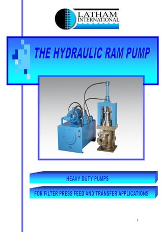
- 2. 2 NTRODUCTION This is a ram type reciprocating piston pump that is driven by a separate electrically powered hydraulic power unit. The pump and hydraulic power unit form a single integrated pump set. The pump is of robust, heavy-duty design and construction with an anticipated working life well in excess of 20 years with minimal maintenance, which gives cost effective handling of slurries. The pump can be used on filter press feed and sludge transfer applications giving a controlled constant flow or a diminishing flow with increased pressure. To obtain higher flow rates pumps can be installed as multiple units and controlled from a single hydraulic power pack. PPLICATION This style of pump was originally designed for the pumping of clay slip in the pottery industry but due to the pumping characteristics of the unit it has been used in many industrial applications. POTABLE WATER WASTE WATER Handling of solids from Alum Ferric sludges. Handling sewage sludges INDUSTRIAL EFFLUENT Pumping a wide range of waste streams CHEMICAL PHARMACEUTICAL INDUSTRY Handling abrasive and crystalline slurries MINING REFINING Pumping tailings, fines and other slurries CERAMICS Raw material transfer and production The hydraulic ram pump has the ability to vary from maximum flow at low pressure to a minimal flow at high pressure, which makes this one of the most ideal pumps to handle the feeding of slurries and effluent steams to a filter press. As the hydraulic supply to the pump is pressure compensated it ensures safe operation even on longer high pressure cycles. The automatic pressure compensating also allows this pump to be used for transfer operation with low maintenance costs on long small bore pipelines where pressure increases can occur due to friction losses. The compensating characteristic of this pump ensures the system can be set at a pre determined pressure which will not be exceeded should blockages occur.
- 3. 3 PERATION CONSTRUCTION OPERATION The pump is a simple robust mechanical construction driven by state of the art variable hydraulics in turn controlled by electronic proximity switches to determine position and direction of the main ram. CONSTRUCTION The pump body and the valve boxes are one piece steel fabrications. The sludge ram is manufactured from stainless steel. The sludge seals are maintenance free dual chevron rings, which are replaceable as a service item without the removal of the sludge ram. The first set of rings provide the initial seal between the main ram and the gland housing, with the upper chevron providing a secondary seal and scrapper facility to ensure clean efficient reciprocation of the ram. Light weight, easily removable, guards enclose the exposed portion of the sludge ram and hydraulic cylinder piston rod. Delivery sludge dampers are provided to eliminate the hammer due to the pulsating action of the pump. These dampers are not coded pressure vessels. The hydraulic cylinder driving the sludge ram is built to off shore specifications and is of a hardwearing design featuring a chrome piston rod. The hydraulic cylinder also features extensive internal guidance and support for the piston rod thereby eliminating lateral forces upon the hydraulic seals, which can promote oil leaks. The top of the hydraulic cylinder features internal, hydraulic cushioning to facilitate absolute control over the sludge ram at the top of the stroke where the ram changes direction from up to down. This contributes to the quite operation of the pump. The hydraulic cylinder is supported upon a fabrication mounted on top of the pump body through which the chrome piston rod passes. SUCTION DELIVERY VALVES Suction and delivery valves are of the ball valve type and consist of a polyurethane iron cored ball and a solid polyurethane valve seat. The fabricated ball valve housing is constructed to allow adequate clearance for the passage of large solids. The passage of material through the valve box causes the ball valve to continually rotate ensuring the ball valve receives even wear, especially when pumping abrasive slurries. Removal of the valve box lid allows easy access to the valve box chamber for ball valve and seat replacement CONSTUCTION MATERIALS For most applications the pump is constructed from fabricated mild steel with a stainless steel main ram and polyurethane gland packings, ball valves and seats. However for applications where temperature or abrasion may be an issue the pump can be constructed with more suitable materials to withstand the duty.
- 4. 4 YDRAULIC POWER PACK The hydraulic unit comprises an hydraulic oil tank beneath which sits an electric motor driving through a bell housing and coupling to a variable speed, pressure compensated hydraulic oil pump. The hydraulic oil tank features internal baffles to encourage circulation and specific movement within the hydraulic oil, which prevents the hydraulic oil from passing straight between the suction and discharge ports in the tank. The tank is sealed except for a breather but has removable panels for access to clean the inside of the tank. A separate, sealed access point is available for topping up the tank. A visual level gauge is provided on the side of the oil tank. A hydraulic pressure gauge and isolator is provided with the hydraulic control valve stack to enable the hydraulic pressures to be set correctly. The hydraulic valve stack features a pressure relief valve and an open centre spool valve, which enables the electric motor to start under no load conditions. A drain plug is provided for draining the hydraulic oil tank during an oil change. A suction strainer is provided to protect the hydraulic oil pump against debris. Full flow oil filtration is provided which features a visual condition indicator. LECTRONIC CHANGEOVER SYSTEM The hydraulic control valves are operated by solenoids positioned on the oil block located on the top of the tank. These control the position of the spool and hence the direction of the main ram. The solenoids are controlled by the proximity switches mounted through the frame at the side of the main ram. This identifies the position of the crosshead and initiates a signal to be sent to reverse the flow of hydraulic oil to the hydraulic cylinder. The length of stroke can be adjusted by the position of the proximity switches in the locating slots. Further fine adjustment can be made using the choke controls beneath the solenoid valve
- 5. 5 UTPUT OF PUMPS Below are the graphs, showing the output of the vertical ram pumps manufactured by Latham International; Note; All pumps optimum operating range between 15 – 30 Output For110mm Pump 5 4 3 2 1 0 5 10 20 30 Performance (strokes/min) Output (m3/hour) Flow Pressure Variable Output For 160mm Pump 9 8 7 6 5 4 3 2 1 0 5 10 20 30 Performance (strokes/min) Output (m3/hour) Flow Pressure Variable (strokes/min). Output for 267mm Pump 35 Output (m3/hour) Flow Pressure 30 25 20 15 10 5 0 Variable 5 10 20 30 Perfomance (strokes/min)
- 6. 6 UTPUT OF PUMPS Output for 320mm Pump 50 40 30 20 10 0 5 10 20 30 Perfomance (strokes/min) Output (m3/hour) Flow Pressure Variable Output for415mm Pump 100 80 60 40 20 0 5 10 20 30 Performance (stokes/min) Output (m3/hour) Flow Pressure Variable Output for 495mm Pump 140 120 100 80 60 40 20 0 5 10 20 30 Performance (strokes/min) Output (m3/hour) Flow Pressure Variable
- 7. 7 ECHNICAL SPECIFICATION PRESSURE MOTOR MAXIMUM PUMP CAPACITY NO OF STROKES STROKE LENGTH MODEL BAR Kw hp M3/HOUR STROKE/MIN mm 110-10 10 2.2 3 4 30 230 110-25 25 5.5 7.5 4 30 230 160-10 10 4.0 5.5 8 30 230 160-25 25 11 15 8 30 230 267-10 10 15 20 30 30 300 267-25 25 45 60 30 30 300 320-10 10 30 40 40 30 320 320-15 15 30 40 40 30 320 320-25 25 37.5 50 40 30 320 415-10 10 45 60 81 30 350 415-25 25 55 74 81 30 350 495-10 10 75 100 121 30 350 495-25 25 185 250 121 30 350 For further information contact: - Latham International Ltd Rowhurst Close Industrial Estate Chesterton Newcastle – under – Lyme Staffs ST5 6bd Tel: +44 (0) 1782 565364 Fax: +44 (0) 1782 564886 e-mail: info@lathaminternational.com web: www.lathaminternational.com