SlideShare a Scribd company logo
1 of 8
Download to read offline
ISSN 2349-7815
International Journal of Recent Research in Electrical and Electronics Engineering (IJRREEE)
Vol. 3, Issue 3, pp: (23-30), Month: July - September 2016, Available at: www.paperpublications.org
Page | 23
Paper Publications
Harmonic Distortion Analysis of Output
Voltage in Multilevel Cascaded H-bridge
Multilevel Inverter for RL Load
1
Pankaj Barman, 2
Ashish Choubey
1
M.E. Student, 2
Assistant Professor, Deptt of Electrical Engineering, JEC Jabalpur, M.P, India
Abstract: Multilevel inverter output voltage produce a staircase output waveform, this waveform look like a
sinusoidal waveform. The multilevel output voltage having less number of harmonics compare to conventional
bipolar inverter output voltage. The desired output of a multilevel inverter is synthesized by several sources of DC
voltage. With an increasing number of DC voltage sources, the converter output voltage waveform approaches
nearly sinusoidal waveform while using a fundamental switching frequency scheme.
Based on the topology multilevel inverters are classified as: (i) Diode-clamped multi-level inverter (ii) Flying-
capacitor multi-level inverter (iii) Cascaded H-bridge multi level inverter
While each of these converters fulfils the basic requirements of a multilevel inverter advantages, there are also
some disadvantages associated with them.
(i) A diode clamped inverter uses many clamping diodes with the increase in level in output voltage. The diode
reverse voltage rating differs for each level and has to be calculated each time as the number of level increases.
(ii) In flying capacitor inverter, the number of storage capacitors required increases with increase in levels.
Balancing the charging and discharging rates of the capacitor is also a problem.
(iii) In cascaded H-bridge inverter which requires reduced number of electronic devices as compared to other two
topologies, there is a drawback of increased number of sources with increase in the output voltage.
In this paper Harmonic distortion analysis of output voltage in a cascaded H-bridge multilevel inverter at different
conduction angles is presented with the help of simulink / matlab.
Keywords: Harmonic distortion, multilevel inverter, conduction angle, harmonic factor, Cascaded H-bridge
inverter.
I. INTRODUCTION
The cascaded H-bridge inverter has drawn tremendous interest due to the great demand of medium-voltage high-power
inverters. It is composed of multiple units of single-phase H-bridge power cells. The H-bridge cells are normally
connected in cascade on their ac side to achieve medium voltage operation and low harmonic distortion. The cascade H-
bridge multilevel inverter requires a number of isolated dc supplies, each of which feeds a H-bridge power cell.
Fig. 1 Single phase 3-level H-bridge inverter
ISSN 2349-7815
International Journal of Recent Research in Electrical and Electronics Engineering (IJRREEE)
Vol. 3, Issue 3, pp: (23-30), Month: July - September 2016, Available at: www.paperpublications.org
Page | 24
Paper Publications
The steps to synthesize the staircase output voltage are as follows:
 The single phase H-bridge cell shown in fig 1, which is the building block for the cascaded H-bridge inverter is
associated with separate dc sources.
 The inverter dc bus voltage is usually fixed, while its ac output voltage can be adjusted by either bipolar or
unipolar modulation schemes. With different combinations of four switches, S1 to S4, each inverter level can generate
three different voltages at the output + , - and 0.
 During inverter operation, switch S1 and S2 are closed at the same time to provide a positive value and a current
path for . Switch S3 and S4 are turned on to provide a negative value with a path for . Depending on load
current angle, the current may flow through the main switch or freewheeling diodes are connected anti parallel with
each switch.
In case of zero level, there are two possible switching patterns to synthesize zero level, they are:
(a) S1 and S3 on, S2 and S4 off
(b) S1 and S3 off and S2 & S4 on.
A simple gate signal, repeated zero level patterns is shown in fig 2.
Fig.2 Repeated Zero-level switching pattern
All zero levels are generated by turning on S1 and S3. Level 1 represents the state when the gate is turned on, and level 0
represents the state when the gate is turned off. S1 & S3 are turned on longer than S2 & S4 in each cycle because the
same zero level switching patterns are used. As a result, S1 and S3 consume more power, getting higher temperature than
the other two switches. To avoid this problem, a different switching pattern for zero level is applied.
In the first zero stage S1 and S3 are turned on, then in the second zero stage, S2 and S4 are turned on instead of S1 and
S3. By applying this method, turn-on time for each switch turns out to be equal as shown in fig 3. It is known as swapped
zero-level switching pattern.
ISSN 2349-7815
International Journal of Recent Research in Electrical and Electronics Engineering (IJRREEE)
Vol. 3, Issue 3, pp: (23-30), Month: July - September 2016, Available at: www.paperpublications.org
Page | 25
Paper Publications
Fig . 3 Swapped zero-level switching pattern
II. SIMULINK MODEL
Fig 4. Simulink model of 7-level inverter
ISSN 2349-7815
International Journal of Recent Research in Electrical and Electronics Engineering (IJRREEE)
Vol. 3, Issue 3, pp: (23-30), Month: July - September 2016, Available at: www.paperpublications.org
Page | 26
Paper Publications
III. RESULTS
Fig. 5 Output voltage of 5 and 7 level inverters
Fig. 6 Load current of 5 and 7 level inverters
ISSN 2349-7815
International Journal of Recent Research in Electrical and Electronics Engineering (IJRREEE)
Vol. 3, Issue 3, pp: (23-30), Month: July - September 2016, Available at: www.paperpublications.org
Page | 27
Paper Publications
Table 1. Total Harmonic distortion ( THD ) of output voltage and Current in a 5-level cascaded H-bridge inverter
at different combinations of conduction angles
Conduction
Angles
= = =
= 28.93 15.7 _ _ _ _
= 23.15 14.44 26.25 14.68 _ _
= 17.8 14.88 23.54 16.4 26.55 16.21
= 17.29 13.89 20.34 15.82 23.79 17.07
= 17.16 15.9 21.19 18 22.94 18.35
= 19.65 17 24 17.99 24 19.35
nduction
angles
= = =
= 27 19.29 _ _ _ _
= 27.05 19.78 28.51 22.2 _ _
= 29.97 21.86 25.16 23.35 28.5 22.02
Table 2. Total Harmonic distortion ( THD ) of output voltage and current in a 7-level cascaded H-bridge inverter
at different combinations of conduction angles
Conduction
angles
=
=
=
=
=
=
= 22.34 14.57 _ _ _ _
= 18.5 14.59 23.68 15.14 _ _
= 13.13 14.55 20.36 15.58 24 17.24
= 12.91 13.97 18.19 16.79 22.8 17.46
= 13.3 16.74 20.13 17.83 21.56 19.53
Conduction
angles
=
=
=
=
= 24 17.24 _ _
= 22.8 17.46 27.75 20.52
= 21.56 19.53 27.16 21.44
Table 3. Output voltage THD and harmonic factor at different combinations of conduction angle ( )
in a 7-level cascaded H-bridge inverter
Order
of harmonic
=
=
=
= 15.94 %
=
=
=
= 12.91 %
=
=
=
=13.3 %
DC .01 % 0.66 % 0. 97 %
2nd
.02 % 1.26 % 1.48 %
3rd
1.66 % 1.62 % 4.1 %
4th
.01 % 1.05 % 0.29 %
5th
6.54 % 7.84 % 4.75 %
6th
0.01 % 0.7 % 1.04 %
ISSN 2349-7815
International Journal of Recent Research in Electrical and Electronics Engineering (IJRREEE)
Vol. 3, Issue 3, pp: (23-30), Month: July - September 2016, Available at: www.paperpublications.org
Page | 28
Paper Publications
7th
6.54 % 0.84 % 3.59 %
8th
0 % 0.27 % 1.87 %
9th
9.44 % 2.84 % 5.64 %
10th
0 % 0.18 % 1.8 %
11th
2.8 % 1.14 % 2.6 %
12th
0 % 0.62 % 0.87 %
13th
2.62 % 1.99 % 2.63 %
Order
of harmonic
=
=
=
= 12.21 %
=
=
=
= 13.81 %
=
=
=
= 17.1 %
DC 1.05 % 0.45 % 0. 01 %
2nd
2.07 % 1.79 % 0.01 %
3rd
5.94 % 8.84 % 1.55 %
4th
0.75 % 1.16 % 0.01 %
5th
3.11 % 0.4 % 11.41 %
6th
1.09 % 0.55 % 0.01 %
7th
2.76 % 4.2 % 6.29 %
8th
0.32 % 0.72 % 0.00 %
9th
2.11 % 1.93 % 4.84 %
10th
1.15 % 1 % 0.00 %
11th
1.32 % 3.23 % 4.92 %
12th
0.85 % 1.16 % 0.0 %
13th
1.51 % 0.92 % 1.37 %
Table 4. Minimum Output voltage THD and harmonic factor at different combinations of conduction angle
( ) in a 7-level cascaded H-bridge inverter
Order
of harmonic
=
=
=
= 13.13 %
=
=
=
= 12.91 %
=
=
=
= 12.21 %
DC .01 % 0.66 % 1.05 %
2nd
.01 % 1.26 % 2.07 %
3rd
0.01 % 1.62 % 5.94 %
4th
.01 % 1.05 % 0.75 %
5th
8.9 % 7.84 % 3.11 %
6th
0.01 % 0.7 % 1.09 %
7th
0.85 % 0.84 % 2.76 %
8th
0 % 0.27 % 0.32 %
9th
0.0 % 2.84 % 2.11 %
10th
0.0 % 0.18 % 1.15 %
11th
3.27 % 1.14 % 1.32 %
12th
0 .0 % 0.62 % 0.85 %
13th
1.92 % 1.99 % 1.51 %
ISSN 2349-7815
International Journal of Recent Research in Electrical and Electronics Engineering (IJRREEE)
Vol. 3, Issue 3, pp: (23-30), Month: July - September 2016, Available at: www.paperpublications.org
Page | 29
Paper Publications
(a)
(b)
(c)
Fig. 7 .Harmonic spectra of minimum voltage THD (a)3-level inverter (b) 5-level inverter (c) 7-level inverter
IV. CONCLUSIONS
 Table1 and 2 shows total harmonic distortion (THD) of the output voltage and current in 5 & 7 level inverters for
different conduction angles.
 From fig.6 it is clear that load current of 7-level inverter is closer to the sinusoidal shape as compare to current in 5-
level inverter.
ISSN 2349-7815
International Journal of Recent Research in Electrical and Electronics Engineering (IJRREEE)
Vol. 3, Issue 3, pp: (23-30), Month: July - September 2016, Available at: www.paperpublications.org
Page | 30
Paper Publications
 From table 3 it is clear that for some combinations of conduction angles, the harmonic factor of some lower order
harmonics is very negligible or almost nearer to zero.
 Fig 7 shows the harmonic spectra of output voltage in 3, 5 and 7 level inverter.
REFERENCES
[1] Muhammad H. Rashid, Third edition, “Power electronics circuits, devices and applications”, Practice Hall of India.
[2] Jainil K. Shah, Manish S. Patel, “Comparative analysis of single phase cascaded H-bridge multilevel inverter”,
IJIREEICE, ISSN: 2321-2004,Vol. 3, Issue April 2015.
[3] Nitin Tyagi , Bharti Yadav , “Performance analysis of 5-level H-bridge multilevel inverter”, IJTRE, ISSN 2347-
4718,Vol. 2, Issue 9, May-2015

More Related Content

What's hot

Analysis of Modulation Strategies for Two-Stage Interleaved Voltage Source In...
Analysis of Modulation Strategies for Two-Stage Interleaved Voltage Source In...Analysis of Modulation Strategies for Two-Stage Interleaved Voltage Source In...
Analysis of Modulation Strategies for Two-Stage Interleaved Voltage Source In...IJARBEST JOURNAL
 
Carrier based hybrid pwm algorithm with reduced common mode voltage
Carrier based hybrid pwm algorithm with reduced common mode voltageCarrier based hybrid pwm algorithm with reduced common mode voltage
Carrier based hybrid pwm algorithm with reduced common mode voltageIAEME Publication
 
Comparative Performance Analysis of Bipolar and Unipolar Single Phase Full Br...
Comparative Performance Analysis of Bipolar and Unipolar Single Phase Full Br...Comparative Performance Analysis of Bipolar and Unipolar Single Phase Full Br...
Comparative Performance Analysis of Bipolar and Unipolar Single Phase Full Br...paperpublications3
 
SIMULATION AND ASSESSMENT OF SINGLE PHASE SEMI-Z-SOURCE INVERTER (S-ZSI)
SIMULATION AND ASSESSMENT OF SINGLE PHASE SEMI-Z-SOURCE INVERTER (S-ZSI)SIMULATION AND ASSESSMENT OF SINGLE PHASE SEMI-Z-SOURCE INVERTER (S-ZSI)
SIMULATION AND ASSESSMENT OF SINGLE PHASE SEMI-Z-SOURCE INVERTER (S-ZSI)IAEME Publication
 
Comparison of symmetrical and asymmetrical cascaded current source multilevel...
Comparison of symmetrical and asymmetrical cascaded current source multilevel...Comparison of symmetrical and asymmetrical cascaded current source multilevel...
Comparison of symmetrical and asymmetrical cascaded current source multilevel...eSAT Journals
 
Comparison of symmetrical and asymmetrical cascaded
Comparison of symmetrical and asymmetrical cascadedComparison of symmetrical and asymmetrical cascaded
Comparison of symmetrical and asymmetrical cascadedeSAT Publishing House
 
11 4oct 6629 10634-1-ed neoteric (edit ari)
11 4oct 6629 10634-1-ed neoteric (edit ari)11 4oct 6629 10634-1-ed neoteric (edit ari)
11 4oct 6629 10634-1-ed neoteric (edit ari)IAESIJEECS
 
Simulation of three-phase bridge rectifier using MATLAB/ SIMULINK for harmoni...
Simulation of three-phase bridge rectifier using MATLAB/ SIMULINK for harmoni...Simulation of three-phase bridge rectifier using MATLAB/ SIMULINK for harmoni...
Simulation of three-phase bridge rectifier using MATLAB/ SIMULINK for harmoni...IJMER
 
Application of PWM Control Strategy on Z-Source Isolated Dual active bridge D...
Application of PWM Control Strategy on Z-Source Isolated Dual active bridge D...Application of PWM Control Strategy on Z-Source Isolated Dual active bridge D...
Application of PWM Control Strategy on Z-Source Isolated Dual active bridge D...IJMER
 
01 PVInverter Project Report
01 PVInverter Project Report01 PVInverter Project Report
01 PVInverter Project ReportDan Fisher
 
Enhancement of Power Quality Using the Combination of Thyristor-Controlled Re...
Enhancement of Power Quality Using the Combination of Thyristor-Controlled Re...Enhancement of Power Quality Using the Combination of Thyristor-Controlled Re...
Enhancement of Power Quality Using the Combination of Thyristor-Controlled Re...IJERD Editor
 
Simulation of IEEE FIRST BANCHMARK Model for SSR Studies
Simulation of IEEE FIRST BANCHMARK Model for SSR StudiesSimulation of IEEE FIRST BANCHMARK Model for SSR Studies
Simulation of IEEE FIRST BANCHMARK Model for SSR Studiesijsrd.com
 
Control analysis of a high frequency resonant inverter for induction cooking ...
Control analysis of a high frequency resonant inverter for induction cooking ...Control analysis of a high frequency resonant inverter for induction cooking ...
Control analysis of a high frequency resonant inverter for induction cooking ...eSAT Journals
 
Total Harmonic Distortion Analysis of Multilevel Inverter Fed To Induction Mo...
Total Harmonic Distortion Analysis of Multilevel Inverter Fed To Induction Mo...Total Harmonic Distortion Analysis of Multilevel Inverter Fed To Induction Mo...
Total Harmonic Distortion Analysis of Multilevel Inverter Fed To Induction Mo...IJERA Editor
 

What's hot (19)

Fw3410821085
Fw3410821085Fw3410821085
Fw3410821085
 
Analysis of Modulation Strategies for Two-Stage Interleaved Voltage Source In...
Analysis of Modulation Strategies for Two-Stage Interleaved Voltage Source In...Analysis of Modulation Strategies for Two-Stage Interleaved Voltage Source In...
Analysis of Modulation Strategies for Two-Stage Interleaved Voltage Source In...
 
IJETT-V3I2P216
IJETT-V3I2P216IJETT-V3I2P216
IJETT-V3I2P216
 
Carrier based hybrid pwm algorithm with reduced common mode voltage
Carrier based hybrid pwm algorithm with reduced common mode voltageCarrier based hybrid pwm algorithm with reduced common mode voltage
Carrier based hybrid pwm algorithm with reduced common mode voltage
 
Comparative Performance Analysis of Bipolar and Unipolar Single Phase Full Br...
Comparative Performance Analysis of Bipolar and Unipolar Single Phase Full Br...Comparative Performance Analysis of Bipolar and Unipolar Single Phase Full Br...
Comparative Performance Analysis of Bipolar and Unipolar Single Phase Full Br...
 
SIMULATION AND ASSESSMENT OF SINGLE PHASE SEMI-Z-SOURCE INVERTER (S-ZSI)
SIMULATION AND ASSESSMENT OF SINGLE PHASE SEMI-Z-SOURCE INVERTER (S-ZSI)SIMULATION AND ASSESSMENT OF SINGLE PHASE SEMI-Z-SOURCE INVERTER (S-ZSI)
SIMULATION AND ASSESSMENT OF SINGLE PHASE SEMI-Z-SOURCE INVERTER (S-ZSI)
 
Comparison of symmetrical and asymmetrical cascaded current source multilevel...
Comparison of symmetrical and asymmetrical cascaded current source multilevel...Comparison of symmetrical and asymmetrical cascaded current source multilevel...
Comparison of symmetrical and asymmetrical cascaded current source multilevel...
 
Comparison of symmetrical and asymmetrical cascaded
Comparison of symmetrical and asymmetrical cascadedComparison of symmetrical and asymmetrical cascaded
Comparison of symmetrical and asymmetrical cascaded
 
11 4oct 6629 10634-1-ed neoteric (edit ari)
11 4oct 6629 10634-1-ed neoteric (edit ari)11 4oct 6629 10634-1-ed neoteric (edit ari)
11 4oct 6629 10634-1-ed neoteric (edit ari)
 
Simulation of three-phase bridge rectifier using MATLAB/ SIMULINK for harmoni...
Simulation of three-phase bridge rectifier using MATLAB/ SIMULINK for harmoni...Simulation of three-phase bridge rectifier using MATLAB/ SIMULINK for harmoni...
Simulation of three-phase bridge rectifier using MATLAB/ SIMULINK for harmoni...
 
Application of PWM Control Strategy on Z-Source Isolated Dual active bridge D...
Application of PWM Control Strategy on Z-Source Isolated Dual active bridge D...Application of PWM Control Strategy on Z-Source Isolated Dual active bridge D...
Application of PWM Control Strategy on Z-Source Isolated Dual active bridge D...
 
01 PVInverter Project Report
01 PVInverter Project Report01 PVInverter Project Report
01 PVInverter Project Report
 
Enhancement of Power Quality Using the Combination of Thyristor-Controlled Re...
Enhancement of Power Quality Using the Combination of Thyristor-Controlled Re...Enhancement of Power Quality Using the Combination of Thyristor-Controlled Re...
Enhancement of Power Quality Using the Combination of Thyristor-Controlled Re...
 
Alternating current voltages
Alternating current voltagesAlternating current voltages
Alternating current voltages
 
Simulation of IEEE FIRST BANCHMARK Model for SSR Studies
Simulation of IEEE FIRST BANCHMARK Model for SSR StudiesSimulation of IEEE FIRST BANCHMARK Model for SSR Studies
Simulation of IEEE FIRST BANCHMARK Model for SSR Studies
 
An34236241
An34236241An34236241
An34236241
 
Control analysis of a high frequency resonant inverter for induction cooking ...
Control analysis of a high frequency resonant inverter for induction cooking ...Control analysis of a high frequency resonant inverter for induction cooking ...
Control analysis of a high frequency resonant inverter for induction cooking ...
 
published paper for ACCET
published paper for ACCETpublished paper for ACCET
published paper for ACCET
 
Total Harmonic Distortion Analysis of Multilevel Inverter Fed To Induction Mo...
Total Harmonic Distortion Analysis of Multilevel Inverter Fed To Induction Mo...Total Harmonic Distortion Analysis of Multilevel Inverter Fed To Induction Mo...
Total Harmonic Distortion Analysis of Multilevel Inverter Fed To Induction Mo...
 

Viewers also liked

Harmonic Distortion Analysis of the Output Voltage in SPWM (Unipolar) Single ...
Harmonic Distortion Analysis of the Output Voltage in SPWM (Unipolar) Single ...Harmonic Distortion Analysis of the Output Voltage in SPWM (Unipolar) Single ...
Harmonic Distortion Analysis of the Output Voltage in SPWM (Unipolar) Single ...paperpublications3
 
The ARM Based Granary Environmental Monitoring and Controlling System using Z...
The ARM Based Granary Environmental Monitoring and Controlling System using Z...The ARM Based Granary Environmental Monitoring and Controlling System using Z...
The ARM Based Granary Environmental Monitoring and Controlling System using Z...paperpublications3
 
Introduction of Programmable Logic Controller to Electric Overhead Travelling...
Introduction of Programmable Logic Controller to Electric Overhead Travelling...Introduction of Programmable Logic Controller to Electric Overhead Travelling...
Introduction of Programmable Logic Controller to Electric Overhead Travelling...paperpublications3
 
Single-Stage Reluctance Type Coilgun
Single-Stage Reluctance Type CoilgunSingle-Stage Reluctance Type Coilgun
Single-Stage Reluctance Type Coilgunpaperpublications3
 
Design of Compensator for Roll Control of Towing Air-Crafts
Design of Compensator for Roll Control of Towing Air-CraftsDesign of Compensator for Roll Control of Towing Air-Crafts
Design of Compensator for Roll Control of Towing Air-Craftspaperpublications3
 
An Overview of Different PWM Techniques to Reduce Total Harmonic Distortion o...
An Overview of Different PWM Techniques to Reduce Total Harmonic Distortion o...An Overview of Different PWM Techniques to Reduce Total Harmonic Distortion o...
An Overview of Different PWM Techniques to Reduce Total Harmonic Distortion o...paperpublications3
 
Analysis of Voltage Sag on Power Distribution Networks with Different Transfo...
Analysis of Voltage Sag on Power Distribution Networks with Different Transfo...Analysis of Voltage Sag on Power Distribution Networks with Different Transfo...
Analysis of Voltage Sag on Power Distribution Networks with Different Transfo...paperpublications3
 
Design and Development of DVR model Using Fuzzy Logic Controller for Voltage ...
Design and Development of DVR model Using Fuzzy Logic Controller for Voltage ...Design and Development of DVR model Using Fuzzy Logic Controller for Voltage ...
Design and Development of DVR model Using Fuzzy Logic Controller for Voltage ...paperpublications3
 
POWER FACTOR IMPROVEMENT OF INDUSTRIAL LOAD BY MATLAB SIMULATION
POWER FACTOR IMPROVEMENT OF INDUSTRIAL LOAD BY MATLAB SIMULATIONPOWER FACTOR IMPROVEMENT OF INDUSTRIAL LOAD BY MATLAB SIMULATION
POWER FACTOR IMPROVEMENT OF INDUSTRIAL LOAD BY MATLAB SIMULATIONpaperpublications3
 
Investigating the Feasibility of Solar Wind Hybrid Systems for Off-Grid Rural...
Investigating the Feasibility of Solar Wind Hybrid Systems for Off-Grid Rural...Investigating the Feasibility of Solar Wind Hybrid Systems for Off-Grid Rural...
Investigating the Feasibility of Solar Wind Hybrid Systems for Off-Grid Rural...paperpublications3
 
Coilgun: Simulation and Analysis
Coilgun: Simulation and AnalysisCoilgun: Simulation and Analysis
Coilgun: Simulation and Analysispaperpublications3
 
A Comparative Analysis of MPWM & SPWM Techniques to Reduce Harmonic Distortio...
A Comparative Analysis of MPWM & SPWM Techniques to Reduce Harmonic Distortio...A Comparative Analysis of MPWM & SPWM Techniques to Reduce Harmonic Distortio...
A Comparative Analysis of MPWM & SPWM Techniques to Reduce Harmonic Distortio...paperpublications3
 
A Comparative Study of Various AC-DC Converters for Low Voltage Energy Harves...
A Comparative Study of Various AC-DC Converters for Low Voltage Energy Harves...A Comparative Study of Various AC-DC Converters for Low Voltage Energy Harves...
A Comparative Study of Various AC-DC Converters for Low Voltage Energy Harves...paperpublications3
 
A new approach for Reducing Noise in ECG signal employing Gradient Descent Me...
A new approach for Reducing Noise in ECG signal employing Gradient Descent Me...A new approach for Reducing Noise in ECG signal employing Gradient Descent Me...
A new approach for Reducing Noise in ECG signal employing Gradient Descent Me...paperpublications3
 
Bridgeless CUK Power Factor Corrector with Regulated Output Voltage
Bridgeless CUK Power Factor Corrector with Regulated Output VoltageBridgeless CUK Power Factor Corrector with Regulated Output Voltage
Bridgeless CUK Power Factor Corrector with Regulated Output Voltagepaperpublications3
 
Sign Language Recognition Using Image Processing For Mute People
Sign Language Recognition Using Image Processing For Mute PeopleSign Language Recognition Using Image Processing For Mute People
Sign Language Recognition Using Image Processing For Mute Peoplepaperpublications3
 
A Comparative Study of GA tuned and PSO tuned PI Controller Based Speed Contr...
A Comparative Study of GA tuned and PSO tuned PI Controller Based Speed Contr...A Comparative Study of GA tuned and PSO tuned PI Controller Based Speed Contr...
A Comparative Study of GA tuned and PSO tuned PI Controller Based Speed Contr...paperpublications3
 
Improved Spider Algorithm for Solving Optimal Reactive Power Dispatch Problem
Improved Spider Algorithm for Solving Optimal Reactive Power Dispatch ProblemImproved Spider Algorithm for Solving Optimal Reactive Power Dispatch Problem
Improved Spider Algorithm for Solving Optimal Reactive Power Dispatch Problempaperpublications3
 
The Harmonic Mitigation in Induction Furnace Using Hybrid Filter
The Harmonic Mitigation in Induction Furnace Using Hybrid FilterThe Harmonic Mitigation in Induction Furnace Using Hybrid Filter
The Harmonic Mitigation in Induction Furnace Using Hybrid Filterpaperpublications3
 
A Review over Different Blur Detection Techniques in Image Processing
A Review over Different Blur Detection Techniques in Image ProcessingA Review over Different Blur Detection Techniques in Image Processing
A Review over Different Blur Detection Techniques in Image Processingpaperpublications3
 

Viewers also liked (20)

Harmonic Distortion Analysis of the Output Voltage in SPWM (Unipolar) Single ...
Harmonic Distortion Analysis of the Output Voltage in SPWM (Unipolar) Single ...Harmonic Distortion Analysis of the Output Voltage in SPWM (Unipolar) Single ...
Harmonic Distortion Analysis of the Output Voltage in SPWM (Unipolar) Single ...
 
The ARM Based Granary Environmental Monitoring and Controlling System using Z...
The ARM Based Granary Environmental Monitoring and Controlling System using Z...The ARM Based Granary Environmental Monitoring and Controlling System using Z...
The ARM Based Granary Environmental Monitoring and Controlling System using Z...
 
Introduction of Programmable Logic Controller to Electric Overhead Travelling...
Introduction of Programmable Logic Controller to Electric Overhead Travelling...Introduction of Programmable Logic Controller to Electric Overhead Travelling...
Introduction of Programmable Logic Controller to Electric Overhead Travelling...
 
Single-Stage Reluctance Type Coilgun
Single-Stage Reluctance Type CoilgunSingle-Stage Reluctance Type Coilgun
Single-Stage Reluctance Type Coilgun
 
Design of Compensator for Roll Control of Towing Air-Crafts
Design of Compensator for Roll Control of Towing Air-CraftsDesign of Compensator for Roll Control of Towing Air-Crafts
Design of Compensator for Roll Control of Towing Air-Crafts
 
An Overview of Different PWM Techniques to Reduce Total Harmonic Distortion o...
An Overview of Different PWM Techniques to Reduce Total Harmonic Distortion o...An Overview of Different PWM Techniques to Reduce Total Harmonic Distortion o...
An Overview of Different PWM Techniques to Reduce Total Harmonic Distortion o...
 
Analysis of Voltage Sag on Power Distribution Networks with Different Transfo...
Analysis of Voltage Sag on Power Distribution Networks with Different Transfo...Analysis of Voltage Sag on Power Distribution Networks with Different Transfo...
Analysis of Voltage Sag on Power Distribution Networks with Different Transfo...
 
Design and Development of DVR model Using Fuzzy Logic Controller for Voltage ...
Design and Development of DVR model Using Fuzzy Logic Controller for Voltage ...Design and Development of DVR model Using Fuzzy Logic Controller for Voltage ...
Design and Development of DVR model Using Fuzzy Logic Controller for Voltage ...
 
POWER FACTOR IMPROVEMENT OF INDUSTRIAL LOAD BY MATLAB SIMULATION
POWER FACTOR IMPROVEMENT OF INDUSTRIAL LOAD BY MATLAB SIMULATIONPOWER FACTOR IMPROVEMENT OF INDUSTRIAL LOAD BY MATLAB SIMULATION
POWER FACTOR IMPROVEMENT OF INDUSTRIAL LOAD BY MATLAB SIMULATION
 
Investigating the Feasibility of Solar Wind Hybrid Systems for Off-Grid Rural...
Investigating the Feasibility of Solar Wind Hybrid Systems for Off-Grid Rural...Investigating the Feasibility of Solar Wind Hybrid Systems for Off-Grid Rural...
Investigating the Feasibility of Solar Wind Hybrid Systems for Off-Grid Rural...
 
Coilgun: Simulation and Analysis
Coilgun: Simulation and AnalysisCoilgun: Simulation and Analysis
Coilgun: Simulation and Analysis
 
A Comparative Analysis of MPWM & SPWM Techniques to Reduce Harmonic Distortio...
A Comparative Analysis of MPWM & SPWM Techniques to Reduce Harmonic Distortio...A Comparative Analysis of MPWM & SPWM Techniques to Reduce Harmonic Distortio...
A Comparative Analysis of MPWM & SPWM Techniques to Reduce Harmonic Distortio...
 
A Comparative Study of Various AC-DC Converters for Low Voltage Energy Harves...
A Comparative Study of Various AC-DC Converters for Low Voltage Energy Harves...A Comparative Study of Various AC-DC Converters for Low Voltage Energy Harves...
A Comparative Study of Various AC-DC Converters for Low Voltage Energy Harves...
 
A new approach for Reducing Noise in ECG signal employing Gradient Descent Me...
A new approach for Reducing Noise in ECG signal employing Gradient Descent Me...A new approach for Reducing Noise in ECG signal employing Gradient Descent Me...
A new approach for Reducing Noise in ECG signal employing Gradient Descent Me...
 
Bridgeless CUK Power Factor Corrector with Regulated Output Voltage
Bridgeless CUK Power Factor Corrector with Regulated Output VoltageBridgeless CUK Power Factor Corrector with Regulated Output Voltage
Bridgeless CUK Power Factor Corrector with Regulated Output Voltage
 
Sign Language Recognition Using Image Processing For Mute People
Sign Language Recognition Using Image Processing For Mute PeopleSign Language Recognition Using Image Processing For Mute People
Sign Language Recognition Using Image Processing For Mute People
 
A Comparative Study of GA tuned and PSO tuned PI Controller Based Speed Contr...
A Comparative Study of GA tuned and PSO tuned PI Controller Based Speed Contr...A Comparative Study of GA tuned and PSO tuned PI Controller Based Speed Contr...
A Comparative Study of GA tuned and PSO tuned PI Controller Based Speed Contr...
 
Improved Spider Algorithm for Solving Optimal Reactive Power Dispatch Problem
Improved Spider Algorithm for Solving Optimal Reactive Power Dispatch ProblemImproved Spider Algorithm for Solving Optimal Reactive Power Dispatch Problem
Improved Spider Algorithm for Solving Optimal Reactive Power Dispatch Problem
 
The Harmonic Mitigation in Induction Furnace Using Hybrid Filter
The Harmonic Mitigation in Induction Furnace Using Hybrid FilterThe Harmonic Mitigation in Induction Furnace Using Hybrid Filter
The Harmonic Mitigation in Induction Furnace Using Hybrid Filter
 
A Review over Different Blur Detection Techniques in Image Processing
A Review over Different Blur Detection Techniques in Image ProcessingA Review over Different Blur Detection Techniques in Image Processing
A Review over Different Blur Detection Techniques in Image Processing
 

Similar to Harmonic Distortion Analysis of Output Voltage in Multilevel Cascaded H-bridge Multilevel Inverter for RL Load

An Overview of Different Multi-level Inverters
An Overview of Different Multi-level InvertersAn Overview of Different Multi-level Inverters
An Overview of Different Multi-level Inverterspaperpublications3
 
6.[36 45]seven level modified cascaded inverter for induction motor drive app...
6.[36 45]seven level modified cascaded inverter for induction motor drive app...6.[36 45]seven level modified cascaded inverter for induction motor drive app...
6.[36 45]seven level modified cascaded inverter for induction motor drive app...Alexander Decker
 
SINGLE PHASE SYMMETRICAL MULTILEVEL INVERTER DESIGN FOR VARIOUS LOADS
SINGLE PHASE SYMMETRICAL MULTILEVEL INVERTER DESIGN FOR VARIOUS LOADSSINGLE PHASE SYMMETRICAL MULTILEVEL INVERTER DESIGN FOR VARIOUS LOADS
SINGLE PHASE SYMMETRICAL MULTILEVEL INVERTER DESIGN FOR VARIOUS LOADSelelijjournal
 
Analysis and hardware implementation of five level cascaded H Bridge inverter
Analysis and hardware implementation of five level cascaded H Bridge inverterAnalysis and hardware implementation of five level cascaded H Bridge inverter
Analysis and hardware implementation of five level cascaded H Bridge inverterIJERA Editor
 
Performance Evaluation of Nine Level Modified CHB Multilevel Inverter for Var...
Performance Evaluation of Nine Level Modified CHB Multilevel Inverter for Var...Performance Evaluation of Nine Level Modified CHB Multilevel Inverter for Var...
Performance Evaluation of Nine Level Modified CHB Multilevel Inverter for Var...IJMER
 
Study and Simulation of Seven Level - Ten Switch Inverter Topology
Study and Simulation of Seven Level - Ten Switch Inverter TopologyStudy and Simulation of Seven Level - Ten Switch Inverter Topology
Study and Simulation of Seven Level - Ten Switch Inverter TopologyMohd Esa
 
AC-AC RESONANT BOOST CONVERTER FOR INDUCTION HEATING WITH CLOSED LOOP CONTROL
AC-AC RESONANT BOOST CONVERTER FOR INDUCTION HEATING WITH CLOSED LOOP CONTROLAC-AC RESONANT BOOST CONVERTER FOR INDUCTION HEATING WITH CLOSED LOOP CONTROL
AC-AC RESONANT BOOST CONVERTER FOR INDUCTION HEATING WITH CLOSED LOOP CONTROLpaperpublications3
 
A DUAL SWITCH BOOST CONVERTER WITH HIGH VOLTAGE GAIN
A DUAL SWITCH BOOST CONVERTER WITH HIGH VOLTAGE GAINA DUAL SWITCH BOOST CONVERTER WITH HIGH VOLTAGE GAIN
A DUAL SWITCH BOOST CONVERTER WITH HIGH VOLTAGE GAINpaperpublications3
 
Modified cascaded multilevel inverter with ga to reduce line to line voltage thd
Modified cascaded multilevel inverter with ga to reduce line to line voltage thdModified cascaded multilevel inverter with ga to reduce line to line voltage thd
Modified cascaded multilevel inverter with ga to reduce line to line voltage thdIAEME Publication
 
Study of Secondary Arc Current Suppression Effects under Different Fault Loca...
Study of Secondary Arc Current Suppression Effects under Different Fault Loca...Study of Secondary Arc Current Suppression Effects under Different Fault Loca...
Study of Secondary Arc Current Suppression Effects under Different Fault Loca...paperpublications3
 
Performance Analysis of Constant-K Low-Pass and Band-Pass Filters in a Uni-Po...
Performance Analysis of Constant-K Low-Pass and Band-Pass Filters in a Uni-Po...Performance Analysis of Constant-K Low-Pass and Band-Pass Filters in a Uni-Po...
Performance Analysis of Constant-K Low-Pass and Band-Pass Filters in a Uni-Po...paperpublications3
 
International Journal of Engineering Research and Development
International Journal of Engineering Research and DevelopmentInternational Journal of Engineering Research and Development
International Journal of Engineering Research and DevelopmentIJERD Editor
 
A Novel Topology of Multilevel Inverter with Reduced Number of Switches and D...
A Novel Topology of Multilevel Inverter with Reduced Number of Switches and D...A Novel Topology of Multilevel Inverter with Reduced Number of Switches and D...
A Novel Topology of Multilevel Inverter with Reduced Number of Switches and D...IAES-IJPEDS
 
Development of a Novel Three Phase Grid-Tied Multilevel Inverter Topology
Development of a Novel Three Phase Grid-Tied Multilevel Inverter TopologyDevelopment of a Novel Three Phase Grid-Tied Multilevel Inverter Topology
Development of a Novel Three Phase Grid-Tied Multilevel Inverter TopologyIAES-IJPEDS
 

Similar to Harmonic Distortion Analysis of Output Voltage in Multilevel Cascaded H-bridge Multilevel Inverter for RL Load (20)

An Overview of Different Multi-level Inverters
An Overview of Different Multi-level InvertersAn Overview of Different Multi-level Inverters
An Overview of Different Multi-level Inverters
 
6.[36 45]seven level modified cascaded inverter for induction motor drive app...
6.[36 45]seven level modified cascaded inverter for induction motor drive app...6.[36 45]seven level modified cascaded inverter for induction motor drive app...
6.[36 45]seven level modified cascaded inverter for induction motor drive app...
 
SINGLE PHASE SYMMETRICAL MULTILEVEL INVERTER DESIGN FOR VARIOUS LOADS
SINGLE PHASE SYMMETRICAL MULTILEVEL INVERTER DESIGN FOR VARIOUS LOADSSINGLE PHASE SYMMETRICAL MULTILEVEL INVERTER DESIGN FOR VARIOUS LOADS
SINGLE PHASE SYMMETRICAL MULTILEVEL INVERTER DESIGN FOR VARIOUS LOADS
 
Analysis and hardware implementation of five level cascaded H Bridge inverter
Analysis and hardware implementation of five level cascaded H Bridge inverterAnalysis and hardware implementation of five level cascaded H Bridge inverter
Analysis and hardware implementation of five level cascaded H Bridge inverter
 
X33128132
X33128132X33128132
X33128132
 
Performance Evaluation of Nine Level Modified CHB Multilevel Inverter for Var...
Performance Evaluation of Nine Level Modified CHB Multilevel Inverter for Var...Performance Evaluation of Nine Level Modified CHB Multilevel Inverter for Var...
Performance Evaluation of Nine Level Modified CHB Multilevel Inverter for Var...
 
Lz3620532059
Lz3620532059Lz3620532059
Lz3620532059
 
Study and Simulation of Seven Level - Ten Switch Inverter Topology
Study and Simulation of Seven Level - Ten Switch Inverter TopologyStudy and Simulation of Seven Level - Ten Switch Inverter Topology
Study and Simulation of Seven Level - Ten Switch Inverter Topology
 
AC-AC RESONANT BOOST CONVERTER FOR INDUCTION HEATING WITH CLOSED LOOP CONTROL
AC-AC RESONANT BOOST CONVERTER FOR INDUCTION HEATING WITH CLOSED LOOP CONTROLAC-AC RESONANT BOOST CONVERTER FOR INDUCTION HEATING WITH CLOSED LOOP CONTROL
AC-AC RESONANT BOOST CONVERTER FOR INDUCTION HEATING WITH CLOSED LOOP CONTROL
 
A DUAL SWITCH BOOST CONVERTER WITH HIGH VOLTAGE GAIN
A DUAL SWITCH BOOST CONVERTER WITH HIGH VOLTAGE GAINA DUAL SWITCH BOOST CONVERTER WITH HIGH VOLTAGE GAIN
A DUAL SWITCH BOOST CONVERTER WITH HIGH VOLTAGE GAIN
 
A New Seven Level Symmetrical Inverter with Reduced Switch Count
A New Seven Level Symmetrical Inverter with Reduced Switch CountA New Seven Level Symmetrical Inverter with Reduced Switch Count
A New Seven Level Symmetrical Inverter with Reduced Switch Count
 
Analysis of series/parallel multilevel inverter with symmetrical and asymmetr...
Analysis of series/parallel multilevel inverter with symmetrical and asymmetr...Analysis of series/parallel multilevel inverter with symmetrical and asymmetr...
Analysis of series/parallel multilevel inverter with symmetrical and asymmetr...
 
Modified cascaded multilevel inverter with ga to reduce line to line voltage thd
Modified cascaded multilevel inverter with ga to reduce line to line voltage thdModified cascaded multilevel inverter with ga to reduce line to line voltage thd
Modified cascaded multilevel inverter with ga to reduce line to line voltage thd
 
Eu35845853
Eu35845853Eu35845853
Eu35845853
 
Dt4301719726
Dt4301719726Dt4301719726
Dt4301719726
 
Study of Secondary Arc Current Suppression Effects under Different Fault Loca...
Study of Secondary Arc Current Suppression Effects under Different Fault Loca...Study of Secondary Arc Current Suppression Effects under Different Fault Loca...
Study of Secondary Arc Current Suppression Effects under Different Fault Loca...
 
Performance Analysis of Constant-K Low-Pass and Band-Pass Filters in a Uni-Po...
Performance Analysis of Constant-K Low-Pass and Band-Pass Filters in a Uni-Po...Performance Analysis of Constant-K Low-Pass and Band-Pass Filters in a Uni-Po...
Performance Analysis of Constant-K Low-Pass and Band-Pass Filters in a Uni-Po...
 
International Journal of Engineering Research and Development
International Journal of Engineering Research and DevelopmentInternational Journal of Engineering Research and Development
International Journal of Engineering Research and Development
 
A Novel Topology of Multilevel Inverter with Reduced Number of Switches and D...
A Novel Topology of Multilevel Inverter with Reduced Number of Switches and D...A Novel Topology of Multilevel Inverter with Reduced Number of Switches and D...
A Novel Topology of Multilevel Inverter with Reduced Number of Switches and D...
 
Development of a Novel Three Phase Grid-Tied Multilevel Inverter Topology
Development of a Novel Three Phase Grid-Tied Multilevel Inverter TopologyDevelopment of a Novel Three Phase Grid-Tied Multilevel Inverter Topology
Development of a Novel Three Phase Grid-Tied Multilevel Inverter Topology
 

Recently uploaded

Databricks Generative AI FoundationCertified.pdf
Databricks Generative AI FoundationCertified.pdfDatabricks Generative AI FoundationCertified.pdf
Databricks Generative AI FoundationCertified.pdfVinayVadlagattu
 
Artificial Intelligence in due diligence
Artificial Intelligence in due diligenceArtificial Intelligence in due diligence
Artificial Intelligence in due diligencemahaffeycheryld
 
Autodesk Construction Cloud (Autodesk Build).pptx
Autodesk Construction Cloud (Autodesk Build).pptxAutodesk Construction Cloud (Autodesk Build).pptx
Autodesk Construction Cloud (Autodesk Build).pptxMustafa Ahmed
 
一比一原版(Griffith毕业证书)格里菲斯大学毕业证成绩单学位证书
一比一原版(Griffith毕业证书)格里菲斯大学毕业证成绩单学位证书一比一原版(Griffith毕业证书)格里菲斯大学毕业证成绩单学位证书
一比一原版(Griffith毕业证书)格里菲斯大学毕业证成绩单学位证书c3384a92eb32
 
litvinenko_Henry_Intrusion_Hong-Kong_2024.pdf
litvinenko_Henry_Intrusion_Hong-Kong_2024.pdflitvinenko_Henry_Intrusion_Hong-Kong_2024.pdf
litvinenko_Henry_Intrusion_Hong-Kong_2024.pdfAlexander Litvinenko
 
History of Indian Railways - the story of Growth & Modernization
History of Indian Railways - the story of Growth & ModernizationHistory of Indian Railways - the story of Growth & Modernization
History of Indian Railways - the story of Growth & ModernizationEmaan Sharma
 
Raashid final report on Embedded Systems
Raashid final report on Embedded SystemsRaashid final report on Embedded Systems
Raashid final report on Embedded SystemsRaashidFaiyazSheikh
 
Theory of Time 2024 (Universal Theory for Everything)
Theory of Time 2024 (Universal Theory for Everything)Theory of Time 2024 (Universal Theory for Everything)
Theory of Time 2024 (Universal Theory for Everything)Ramkumar k
 
01-vogelsanger-stanag-4178-ed-2-the-new-nato-standard-for-nitrocellulose-test...
01-vogelsanger-stanag-4178-ed-2-the-new-nato-standard-for-nitrocellulose-test...01-vogelsanger-stanag-4178-ed-2-the-new-nato-standard-for-nitrocellulose-test...
01-vogelsanger-stanag-4178-ed-2-the-new-nato-standard-for-nitrocellulose-test...AshwaniAnuragi1
 
Circuit Breakers for Engineering Students
Circuit Breakers for Engineering StudentsCircuit Breakers for Engineering Students
Circuit Breakers for Engineering Studentskannan348865
 
Instruct Nirmaana 24-Smart and Lean Construction Through Technology.pdf
Instruct Nirmaana 24-Smart and Lean Construction Through Technology.pdfInstruct Nirmaana 24-Smart and Lean Construction Through Technology.pdf
Instruct Nirmaana 24-Smart and Lean Construction Through Technology.pdfEr.Sonali Nasikkar
 
handbook on reinforce concrete and detailing
handbook on reinforce concrete and detailinghandbook on reinforce concrete and detailing
handbook on reinforce concrete and detailingAshishSingh1301
 
Fuzzy logic method-based stress detector with blood pressure and body tempera...
Fuzzy logic method-based stress detector with blood pressure and body tempera...Fuzzy logic method-based stress detector with blood pressure and body tempera...
Fuzzy logic method-based stress detector with blood pressure and body tempera...IJECEIAES
 
NEWLETTER FRANCE HELICES/ SDS SURFACE DRIVES - MAY 2024
NEWLETTER FRANCE HELICES/ SDS SURFACE DRIVES - MAY 2024NEWLETTER FRANCE HELICES/ SDS SURFACE DRIVES - MAY 2024
NEWLETTER FRANCE HELICES/ SDS SURFACE DRIVES - MAY 2024EMMANUELLEFRANCEHELI
 
Augmented Reality (AR) with Augin Software.pptx
Augmented Reality (AR) with Augin Software.pptxAugmented Reality (AR) with Augin Software.pptx
Augmented Reality (AR) with Augin Software.pptxMustafa Ahmed
 
Max. shear stress theory-Maximum Shear Stress Theory ​ Maximum Distortional ...
Max. shear stress theory-Maximum Shear Stress Theory ​  Maximum Distortional ...Max. shear stress theory-Maximum Shear Stress Theory ​  Maximum Distortional ...
Max. shear stress theory-Maximum Shear Stress Theory ​ Maximum Distortional ...ronahami
 
Worksharing and 3D Modeling with Revit.pptx
Worksharing and 3D Modeling with Revit.pptxWorksharing and 3D Modeling with Revit.pptx
Worksharing and 3D Modeling with Revit.pptxMustafa Ahmed
 
5G and 6G refer to generations of mobile network technology, each representin...
5G and 6G refer to generations of mobile network technology, each representin...5G and 6G refer to generations of mobile network technology, each representin...
5G and 6G refer to generations of mobile network technology, each representin...archanaece3
 
21P35A0312 Internship eccccccReport.docx
21P35A0312 Internship eccccccReport.docx21P35A0312 Internship eccccccReport.docx
21P35A0312 Internship eccccccReport.docxrahulmanepalli02
 

Recently uploaded (20)

Databricks Generative AI FoundationCertified.pdf
Databricks Generative AI FoundationCertified.pdfDatabricks Generative AI FoundationCertified.pdf
Databricks Generative AI FoundationCertified.pdf
 
Artificial Intelligence in due diligence
Artificial Intelligence in due diligenceArtificial Intelligence in due diligence
Artificial Intelligence in due diligence
 
Signal Processing and Linear System Analysis
Signal Processing and Linear System AnalysisSignal Processing and Linear System Analysis
Signal Processing and Linear System Analysis
 
Autodesk Construction Cloud (Autodesk Build).pptx
Autodesk Construction Cloud (Autodesk Build).pptxAutodesk Construction Cloud (Autodesk Build).pptx
Autodesk Construction Cloud (Autodesk Build).pptx
 
一比一原版(Griffith毕业证书)格里菲斯大学毕业证成绩单学位证书
一比一原版(Griffith毕业证书)格里菲斯大学毕业证成绩单学位证书一比一原版(Griffith毕业证书)格里菲斯大学毕业证成绩单学位证书
一比一原版(Griffith毕业证书)格里菲斯大学毕业证成绩单学位证书
 
litvinenko_Henry_Intrusion_Hong-Kong_2024.pdf
litvinenko_Henry_Intrusion_Hong-Kong_2024.pdflitvinenko_Henry_Intrusion_Hong-Kong_2024.pdf
litvinenko_Henry_Intrusion_Hong-Kong_2024.pdf
 
History of Indian Railways - the story of Growth & Modernization
History of Indian Railways - the story of Growth & ModernizationHistory of Indian Railways - the story of Growth & Modernization
History of Indian Railways - the story of Growth & Modernization
 
Raashid final report on Embedded Systems
Raashid final report on Embedded SystemsRaashid final report on Embedded Systems
Raashid final report on Embedded Systems
 
Theory of Time 2024 (Universal Theory for Everything)
Theory of Time 2024 (Universal Theory for Everything)Theory of Time 2024 (Universal Theory for Everything)
Theory of Time 2024 (Universal Theory for Everything)
 
01-vogelsanger-stanag-4178-ed-2-the-new-nato-standard-for-nitrocellulose-test...
01-vogelsanger-stanag-4178-ed-2-the-new-nato-standard-for-nitrocellulose-test...01-vogelsanger-stanag-4178-ed-2-the-new-nato-standard-for-nitrocellulose-test...
01-vogelsanger-stanag-4178-ed-2-the-new-nato-standard-for-nitrocellulose-test...
 
Circuit Breakers for Engineering Students
Circuit Breakers for Engineering StudentsCircuit Breakers for Engineering Students
Circuit Breakers for Engineering Students
 
Instruct Nirmaana 24-Smart and Lean Construction Through Technology.pdf
Instruct Nirmaana 24-Smart and Lean Construction Through Technology.pdfInstruct Nirmaana 24-Smart and Lean Construction Through Technology.pdf
Instruct Nirmaana 24-Smart and Lean Construction Through Technology.pdf
 
handbook on reinforce concrete and detailing
handbook on reinforce concrete and detailinghandbook on reinforce concrete and detailing
handbook on reinforce concrete and detailing
 
Fuzzy logic method-based stress detector with blood pressure and body tempera...
Fuzzy logic method-based stress detector with blood pressure and body tempera...Fuzzy logic method-based stress detector with blood pressure and body tempera...
Fuzzy logic method-based stress detector with blood pressure and body tempera...
 
NEWLETTER FRANCE HELICES/ SDS SURFACE DRIVES - MAY 2024
NEWLETTER FRANCE HELICES/ SDS SURFACE DRIVES - MAY 2024NEWLETTER FRANCE HELICES/ SDS SURFACE DRIVES - MAY 2024
NEWLETTER FRANCE HELICES/ SDS SURFACE DRIVES - MAY 2024
 
Augmented Reality (AR) with Augin Software.pptx
Augmented Reality (AR) with Augin Software.pptxAugmented Reality (AR) with Augin Software.pptx
Augmented Reality (AR) with Augin Software.pptx
 
Max. shear stress theory-Maximum Shear Stress Theory ​ Maximum Distortional ...
Max. shear stress theory-Maximum Shear Stress Theory ​  Maximum Distortional ...Max. shear stress theory-Maximum Shear Stress Theory ​  Maximum Distortional ...
Max. shear stress theory-Maximum Shear Stress Theory ​ Maximum Distortional ...
 
Worksharing and 3D Modeling with Revit.pptx
Worksharing and 3D Modeling with Revit.pptxWorksharing and 3D Modeling with Revit.pptx
Worksharing and 3D Modeling with Revit.pptx
 
5G and 6G refer to generations of mobile network technology, each representin...
5G and 6G refer to generations of mobile network technology, each representin...5G and 6G refer to generations of mobile network technology, each representin...
5G and 6G refer to generations of mobile network technology, each representin...
 
21P35A0312 Internship eccccccReport.docx
21P35A0312 Internship eccccccReport.docx21P35A0312 Internship eccccccReport.docx
21P35A0312 Internship eccccccReport.docx
 

Harmonic Distortion Analysis of Output Voltage in Multilevel Cascaded H-bridge Multilevel Inverter for RL Load

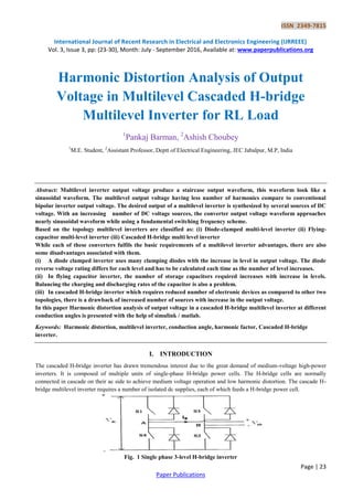
  • 1. ISSN 2349-7815 International Journal of Recent Research in Electrical and Electronics Engineering (IJRREEE) Vol. 3, Issue 3, pp: (23-30), Month: July - September 2016, Available at: www.paperpublications.org Page | 23 Paper Publications Harmonic Distortion Analysis of Output Voltage in Multilevel Cascaded H-bridge Multilevel Inverter for RL Load 1 Pankaj Barman, 2 Ashish Choubey 1 M.E. Student, 2 Assistant Professor, Deptt of Electrical Engineering, JEC Jabalpur, M.P, India Abstract: Multilevel inverter output voltage produce a staircase output waveform, this waveform look like a sinusoidal waveform. The multilevel output voltage having less number of harmonics compare to conventional bipolar inverter output voltage. The desired output of a multilevel inverter is synthesized by several sources of DC voltage. With an increasing number of DC voltage sources, the converter output voltage waveform approaches nearly sinusoidal waveform while using a fundamental switching frequency scheme. Based on the topology multilevel inverters are classified as: (i) Diode-clamped multi-level inverter (ii) Flying- capacitor multi-level inverter (iii) Cascaded H-bridge multi level inverter While each of these converters fulfils the basic requirements of a multilevel inverter advantages, there are also some disadvantages associated with them. (i) A diode clamped inverter uses many clamping diodes with the increase in level in output voltage. The diode reverse voltage rating differs for each level and has to be calculated each time as the number of level increases. (ii) In flying capacitor inverter, the number of storage capacitors required increases with increase in levels. Balancing the charging and discharging rates of the capacitor is also a problem. (iii) In cascaded H-bridge inverter which requires reduced number of electronic devices as compared to other two topologies, there is a drawback of increased number of sources with increase in the output voltage. In this paper Harmonic distortion analysis of output voltage in a cascaded H-bridge multilevel inverter at different conduction angles is presented with the help of simulink / matlab. Keywords: Harmonic distortion, multilevel inverter, conduction angle, harmonic factor, Cascaded H-bridge inverter. I. INTRODUCTION The cascaded H-bridge inverter has drawn tremendous interest due to the great demand of medium-voltage high-power inverters. It is composed of multiple units of single-phase H-bridge power cells. The H-bridge cells are normally connected in cascade on their ac side to achieve medium voltage operation and low harmonic distortion. The cascade H- bridge multilevel inverter requires a number of isolated dc supplies, each of which feeds a H-bridge power cell. Fig. 1 Single phase 3-level H-bridge inverter
  • 2. ISSN 2349-7815 International Journal of Recent Research in Electrical and Electronics Engineering (IJRREEE) Vol. 3, Issue 3, pp: (23-30), Month: July - September 2016, Available at: www.paperpublications.org Page | 24 Paper Publications The steps to synthesize the staircase output voltage are as follows:  The single phase H-bridge cell shown in fig 1, which is the building block for the cascaded H-bridge inverter is associated with separate dc sources.  The inverter dc bus voltage is usually fixed, while its ac output voltage can be adjusted by either bipolar or unipolar modulation schemes. With different combinations of four switches, S1 to S4, each inverter level can generate three different voltages at the output + , - and 0.  During inverter operation, switch S1 and S2 are closed at the same time to provide a positive value and a current path for . Switch S3 and S4 are turned on to provide a negative value with a path for . Depending on load current angle, the current may flow through the main switch or freewheeling diodes are connected anti parallel with each switch. In case of zero level, there are two possible switching patterns to synthesize zero level, they are: (a) S1 and S3 on, S2 and S4 off (b) S1 and S3 off and S2 & S4 on. A simple gate signal, repeated zero level patterns is shown in fig 2. Fig.2 Repeated Zero-level switching pattern All zero levels are generated by turning on S1 and S3. Level 1 represents the state when the gate is turned on, and level 0 represents the state when the gate is turned off. S1 & S3 are turned on longer than S2 & S4 in each cycle because the same zero level switching patterns are used. As a result, S1 and S3 consume more power, getting higher temperature than the other two switches. To avoid this problem, a different switching pattern for zero level is applied. In the first zero stage S1 and S3 are turned on, then in the second zero stage, S2 and S4 are turned on instead of S1 and S3. By applying this method, turn-on time for each switch turns out to be equal as shown in fig 3. It is known as swapped zero-level switching pattern.
  • 3. ISSN 2349-7815 International Journal of Recent Research in Electrical and Electronics Engineering (IJRREEE) Vol. 3, Issue 3, pp: (23-30), Month: July - September 2016, Available at: www.paperpublications.org Page | 25 Paper Publications Fig . 3 Swapped zero-level switching pattern II. SIMULINK MODEL Fig 4. Simulink model of 7-level inverter
  • 4. ISSN 2349-7815 International Journal of Recent Research in Electrical and Electronics Engineering (IJRREEE) Vol. 3, Issue 3, pp: (23-30), Month: July - September 2016, Available at: www.paperpublications.org Page | 26 Paper Publications III. RESULTS Fig. 5 Output voltage of 5 and 7 level inverters Fig. 6 Load current of 5 and 7 level inverters
  • 5. ISSN 2349-7815 International Journal of Recent Research in Electrical and Electronics Engineering (IJRREEE) Vol. 3, Issue 3, pp: (23-30), Month: July - September 2016, Available at: www.paperpublications.org Page | 27 Paper Publications Table 1. Total Harmonic distortion ( THD ) of output voltage and Current in a 5-level cascaded H-bridge inverter at different combinations of conduction angles Conduction Angles = = = = 28.93 15.7 _ _ _ _ = 23.15 14.44 26.25 14.68 _ _ = 17.8 14.88 23.54 16.4 26.55 16.21 = 17.29 13.89 20.34 15.82 23.79 17.07 = 17.16 15.9 21.19 18 22.94 18.35 = 19.65 17 24 17.99 24 19.35 nduction angles = = = = 27 19.29 _ _ _ _ = 27.05 19.78 28.51 22.2 _ _ = 29.97 21.86 25.16 23.35 28.5 22.02 Table 2. Total Harmonic distortion ( THD ) of output voltage and current in a 7-level cascaded H-bridge inverter at different combinations of conduction angles Conduction angles = = = = = = = 22.34 14.57 _ _ _ _ = 18.5 14.59 23.68 15.14 _ _ = 13.13 14.55 20.36 15.58 24 17.24 = 12.91 13.97 18.19 16.79 22.8 17.46 = 13.3 16.74 20.13 17.83 21.56 19.53 Conduction angles = = = = = 24 17.24 _ _ = 22.8 17.46 27.75 20.52 = 21.56 19.53 27.16 21.44 Table 3. Output voltage THD and harmonic factor at different combinations of conduction angle ( ) in a 7-level cascaded H-bridge inverter Order of harmonic = = = = 15.94 % = = = = 12.91 % = = = =13.3 % DC .01 % 0.66 % 0. 97 % 2nd .02 % 1.26 % 1.48 % 3rd 1.66 % 1.62 % 4.1 % 4th .01 % 1.05 % 0.29 % 5th 6.54 % 7.84 % 4.75 % 6th 0.01 % 0.7 % 1.04 %
  • 6. ISSN 2349-7815 International Journal of Recent Research in Electrical and Electronics Engineering (IJRREEE) Vol. 3, Issue 3, pp: (23-30), Month: July - September 2016, Available at: www.paperpublications.org Page | 28 Paper Publications 7th 6.54 % 0.84 % 3.59 % 8th 0 % 0.27 % 1.87 % 9th 9.44 % 2.84 % 5.64 % 10th 0 % 0.18 % 1.8 % 11th 2.8 % 1.14 % 2.6 % 12th 0 % 0.62 % 0.87 % 13th 2.62 % 1.99 % 2.63 % Order of harmonic = = = = 12.21 % = = = = 13.81 % = = = = 17.1 % DC 1.05 % 0.45 % 0. 01 % 2nd 2.07 % 1.79 % 0.01 % 3rd 5.94 % 8.84 % 1.55 % 4th 0.75 % 1.16 % 0.01 % 5th 3.11 % 0.4 % 11.41 % 6th 1.09 % 0.55 % 0.01 % 7th 2.76 % 4.2 % 6.29 % 8th 0.32 % 0.72 % 0.00 % 9th 2.11 % 1.93 % 4.84 % 10th 1.15 % 1 % 0.00 % 11th 1.32 % 3.23 % 4.92 % 12th 0.85 % 1.16 % 0.0 % 13th 1.51 % 0.92 % 1.37 % Table 4. Minimum Output voltage THD and harmonic factor at different combinations of conduction angle ( ) in a 7-level cascaded H-bridge inverter Order of harmonic = = = = 13.13 % = = = = 12.91 % = = = = 12.21 % DC .01 % 0.66 % 1.05 % 2nd .01 % 1.26 % 2.07 % 3rd 0.01 % 1.62 % 5.94 % 4th .01 % 1.05 % 0.75 % 5th 8.9 % 7.84 % 3.11 % 6th 0.01 % 0.7 % 1.09 % 7th 0.85 % 0.84 % 2.76 % 8th 0 % 0.27 % 0.32 % 9th 0.0 % 2.84 % 2.11 % 10th 0.0 % 0.18 % 1.15 % 11th 3.27 % 1.14 % 1.32 % 12th 0 .0 % 0.62 % 0.85 % 13th 1.92 % 1.99 % 1.51 %
  • 7. ISSN 2349-7815 International Journal of Recent Research in Electrical and Electronics Engineering (IJRREEE) Vol. 3, Issue 3, pp: (23-30), Month: July - September 2016, Available at: www.paperpublications.org Page | 29 Paper Publications (a) (b) (c) Fig. 7 .Harmonic spectra of minimum voltage THD (a)3-level inverter (b) 5-level inverter (c) 7-level inverter IV. CONCLUSIONS  Table1 and 2 shows total harmonic distortion (THD) of the output voltage and current in 5 & 7 level inverters for different conduction angles.  From fig.6 it is clear that load current of 7-level inverter is closer to the sinusoidal shape as compare to current in 5- level inverter.
  • 8. ISSN 2349-7815 International Journal of Recent Research in Electrical and Electronics Engineering (IJRREEE) Vol. 3, Issue 3, pp: (23-30), Month: July - September 2016, Available at: www.paperpublications.org Page | 30 Paper Publications  From table 3 it is clear that for some combinations of conduction angles, the harmonic factor of some lower order harmonics is very negligible or almost nearer to zero.  Fig 7 shows the harmonic spectra of output voltage in 3, 5 and 7 level inverter. REFERENCES [1] Muhammad H. Rashid, Third edition, “Power electronics circuits, devices and applications”, Practice Hall of India. [2] Jainil K. Shah, Manish S. Patel, “Comparative analysis of single phase cascaded H-bridge multilevel inverter”, IJIREEICE, ISSN: 2321-2004,Vol. 3, Issue April 2015. [3] Nitin Tyagi , Bharti Yadav , “Performance analysis of 5-level H-bridge multilevel inverter”, IJTRE, ISSN 2347- 4718,Vol. 2, Issue 9, May-2015