SlideShare a Scribd company logo
1 of 30
Download to read offline
Chapter 5
Milling Machines
5.1 Introduction
After lathes, milling machines are the most widely used for manufacturing applications. In
milling, the work piece is fed into a rotating milling cutter, which a multi-point tool as
shown in Fig. 5.1, unlike a lathe, which uses a single point cutting tool. The tool used in
milling cutter.
Fig.5.1. Schematic diagram of a milling operation
The milling process is characterised by:
1) Interrupted cutting: Each of the cutting edges removes material for only a part of the
rotation of the miller cutting. As a result, the cutting- edge has time to cool before it
again removes material. Thus the milling operation is much more cooler compared to
the turning operation. This allows for a much larger material rates.
2) Small size of chips: Through the size of the chips is small, in view of the multiple
cutting edges in contact a large amount of material is removed and as result the
component is generally completed in a single pass unlike the turning process which
required a large number of cuts for finishing.
3) Variation in chip thickness: This contributes to the non-steady state cyclic conditions
of varying cutting forces during the contact of the cutting edge with
5.2
the chip thickness varying from zero to maximum size or vice versa. This cyclic
variation of the force can excite any of the natural frequencies of the machine
tool system and is harmful to the tool life and surface finish generated.
A milling machine is one of the most versatile machine tools. It is adaptable for
quantity production as well as in job shops and tool rooms. The versatility of milling
is because of the large variety of accessories and tools available with milling
machines. The typical tolerance expected from the process is about ± 0.050mm.
5.2 Types of Milling Machines
To satisfy various requirements milling machines come in a number of sizes and
varieties. In view of the large material removal rates milling machines come with a
very rigid spindle and large power. The variety rigid spindle and large power. The
varieties of milling machines available are:
1) Knee and column type
a) Horizontal c) Universal
b) Vertical d) Turret type.
These are the general purpose-milling machines, which have a high degree of
flexibility and are employed for all types of works including batch manufacturing.
A large variety of attachments to improve the flexibility are available for this class of
milling machines.
2) Production (Bed) type
a) Simplex
b) Duplex
c) Triplex
These machines are generally meant for regular production involving large batch
sizes. The flexibility less in these machines, which is suitable for productivity
enhancement.
3) Piano millers
These machines are used only for very large work pieces involving table travels
in meters.
4) Special type
a) Rotary type
b) Drum type
c) Copy milling (Die sinking machine)
d) Key way milling machines
e) Spline shaft milling machines.
These machines provided special facilities to suit specific applications that are
not catered to by the other classes or milling machines.
Milling Machines 5.3
5.3 Knee and Column Milling Machines
5.3.1 Horizontal Knee and Column Type Milling Machines
The knee and column type is the most commonly used machine in view of its
flexibility and easier setup. A typical machine construction is shown in Fig. 5.2 for
the horizontal axis. The knee houses the feed mechanism and mounts the saddle
and table. The table basically has the T-slots running along the X-axis for the purpose
of work holding. The table moves along the Y-axis on the guide ways provided on
the knee. The feed is provided either manually with a hand wheel or connected for
automatic by the lead screw, which in turn is coupled to the main spindle drive.
The knee can move up and down (Z-axis) on a dovetail provided on the column.
The massive column at the back of the machine houses all the power train
including the motor and the spindle gearbox. The power for feed motor is provided
for the gear, box as well.
Fig.5.2. Horizontal knee and Column type milling machine
While the longitudinal and traverse motions are provided with automatic motion,
the raising of the knee is generally made manually.
The spindle is located at the top end of the column. The arbur used to amount the
milling cutters is mounted in the spindle and is provided with a support on the
other end to take care of the heavy cutting force by means of an overarm with
bearing. As shown in Fig.5.2 the overarm extends from the column with "a rigid
design. The spindle nose has the standard morse taper of the suitable size depending
upon the machine size.
The milling cutters are mounted on the arbour at any desired position, the rest oi
the length being filled by standard hardened collars of varying widths to fix the
position of the cutter. The arbour is clamped in the spindle with the help of a cjraw
bar and then fixed with nuts.
Milling machines are generally specified on the following basis:
1) Size of the table, which specifies the actual working area on the table and
relates to the maximum size of the work piece that can be accommodated.
2) Amount of table travel which gives maximum axis movement that is possible
5.4
3) Horse power of the spindle, which actually specifies the power of the spindle
motor used. Smaller machines may come with 1 to 3hp while the production
machines may go from 5 to 50hp.
5.3.2 Vertical Knee and Column Type Milling Machine
Another type of knee column milling machine is the vertical axis type. Its construction
is very similar to the horizontal axis type, except for the spindle type and location.
The spindle is located in the vertical direction and is suitable for using the shank
mounted milling cutters such as end mills. In view of the location of the tool, the
setting up of the work piece and observing the machining operation is more convenient.
Another type of knee and column milling machine is flexible (Fig. 5.4) and
suitable for machining complex cavities such as die cavities in tool rooms.
Fig.5.3. Vertical Knee and Column Type Milling Machine
Fig.5.4. Some of the milling operations normally carried
out on vertical axis machine.
Milling Machines 5.5
The vertical head is provided with a swivelling facility in horizontal direction where
by the cutter axis can be swivelled. This is useful for tool rooms where more complex
milling operations are carried out.
5.4 Bed Type Milling Machine
In production milling machines it is desirable to increase the metal removal rates. If
it is done on conventional machines by increasing the depth of cut, there is possibility
I of chatter. Hence another variety of milling machines named as bed type machines
are used which are made more rugged and are capable of removing more material.
The rugged is obtained as a consequence of the reduction in versatility. The table in
the case of bed type machines is directly mounted on the bed and is provided with
only longitudinal motion. The spindle moves along with the column to provide the
cutting action. Simplex machines (Fig.5.5) are the ones with only one spindle head
while duplex machines have two spindles (Fig.5.6). The two spindles are located on
either side of a heavy work piece and remove material from both sides simultaneously.
Fig.5.5. Simplex bed type milling machine
Fig.5.6. Duplex bed type milling machine
5.6
5.5 Universal Milling Machine
It is the most versatile of all the milling machines. It is capable of performing most
of the machining operations. It is similar to a plain milling machine and differs only
in respect of the table movements. In a universal milling machine, in addition to
three movements as incorporated in a plain milling machine, the table may have a
fourth movement, i.e., the table can be swivelled in a horizontal plane. In this machine
the saddle is made in two parts. The upper part with the work table fitted on it can
be made free over the lower one and thus can be swivelled to any position M the
horizontal plane. This special feature enables the work to be set at an angle with the
cutter for milling helical and spiral flutes and grooves.
5.6 Size of Milling Machine
The size of the column and knee type-milling machine is designated by the dimensions
of the working surface of the table and its maximum length of longitudinal, cross
and vertical travel of the table. The following are the typical size of a horizontal
knee type-milling machine.
Table length x width = 150 x 310mm.
Power traverse = longitudinal x cross x vertical
= 650 x 235 x 420mm.
In addition to the above dimensions number of spindle speeds, number feeds,
spindle nose taper, power available, net weight and the floor space required, etc.
should also be stated in order to specify the machine fully.
5.7 Method of Cutting
The milling operations are divided into two distinct methods.
5.7.1 Conventional or Up-Milling (Fig.5.7)
The work is fed into the rotation of the cutter. The chip is of minimum thickness at
the start of the cut and is so light that the cutter has a tendency to slide over the
work until sufficient pressure is built up to bite into the work. This alternate sliding
leaves marks on the milled surface.
Fig.5.7. Conventional or up milling
Milling Machines 5.7
5.7.2 Climb or Down Milling (Fig.5.8)
The work moves in the same direction as the
rotation of the cutter. Full engagement of the
tooth is instantaneous. There is no sliding action
in this type of milling and hence better surface
finish is obtained. The cutter presses the work
down on the work table. This is the main
advantage of climb milling. But it is not
recommended on light machines or on large
older machines that are not in top condition or
fitted with an anti-backlash device to take up
play. There should not be any play in the table.
Also the work and holding device must be
mounted securely otherwise there would be a
danger of serious accident.
5.8 Milling Operations
The following are the different operations performed in a milling machine.
1) Plain milling
2) Face milling
3) Form milling
4) Straddle milling
5) Angular milling
6) Gang milling
7) Profile milling
8) End milling
9) Helical milling
10) Gear cutting
5.8.1 Plain or slab or Peripheral milling
It is the operation of production of a plain,
flat, horizontal surface parallel to the axis of
rotation of a plain milling cutter. The two
types of peripheral milling are climb or down
milling and conventional or up milling. In
this operation the work and the cutter are
secured properly on the machine. The
operation is illustrated in Fig.5.9.
Fig.5.9. Slab milling
Fig.5.8. Climb or Down-milling
5.8
5.8.2 Face Milling
It is performed by a face-milling cutter rotated about an axis perpendicular to the
work surface. It is carried out in a plain milling machine and the cutter is mounted
on a stub arbor to produce a flat surface. The operation is illustrated in the Fig.5.10.
*=?
1. Face milling Cutter. 2. Work.
Fig.5.10. Face milling
5.8.3 Form Milling
It is the operation of irregular contours by using cutters. The irregular contour may
be convex. Concave or of any other shape. The form milling operation is illustrated
in theFig.5.11.
Fig.5.11. Form milling
5.8.4 Straddle Milling
It is a milling operation in which a pair of side milling cutters are used for machining
two parallel vertical surfaces of a work-piece simultaneously as shown in the
Fig.5.12.
Milling Machines 5.9
Fig.5.12. Straddle milling
5.8.5 Angular Milling
It is the milling process, which is used for
machining a flat surface at an angle, other than
i right angle to the axis of the revolving cutter.
The cutter used may be a single or double angle
cutter depending upon whether a single surface
is to be machined or two mutually inclined
surfaces simultaneously as shown in the
Fig.5.13.
5.8.6 Gang Milling
[is the operation of machining several surfaces
of a work-piece simultaneously by feeding the
table against a number of cutters having same
or different diameters mounted on the arbur of
3 machine. This method saves much of ma-
chining time and is widely used in repetitive
work. The cutting speed of a gang of cutters is
calculated from the cutter of the larges t diam-
eter. The operation is illustrated in Fig. 5.14.
5.8.7 Profile Milling
Fig.5.13. Angular milling
Fig.5.14. Gang milling
Fig.5.15. Profile milling
5.5
It is the operation of reproduction of an outline of a template or complex shape of a
master die on a work piece. Different cutters may be used for profile milling. An end
mill is one of the most-widely used milling cutter in profile milling work as illustrated
intheFig.5.15.
5.8.8 End Milling
It is the operation of production of a flat surface,
which may be vertical, horizontal or at an angle in
reference to the table surface. The cutter used is an
end mill. A vertical milling machine is most suitable
for end milling operation. The Fig. 5.16 illustrates the
production of slots in a work-piece using end milling
cutter.
5.8.9 Helical Milling
It is the operation of production of helical flutes of
grooves around the periphery of a cylindrical or
conical work piece. The operation is performed by
swivelling the table to the required helix angle and then by rotating and feeding the
work against rotary cutting edges of a milling cutter. The production of helical
milling cutters, helical gears, cutting helical grooves of flutes on a drill blank or a
reamer are the examples of helical-milling.
5.8.10 Gear Cutting
The gear cutting operation is performed in a milling machine by using a form-
relieved cutter. The cutter may be cylindrical type or end mill type. The cutter
profile corresponds exactly with the tooth space of the gear. Equally spaced gear
teeth are cut in a gear blank by holding the work on a universal dividing head and
then indexing it. The gear cutting operation by a formed cutter is illustrated the
Fig.5.17.
Fig.5.16. End milling
Fig.5.17. Gear cutting
Milling Machines 5.11
5.9 Work Holding Devices
A milling machine table comes with precision parallel T-slots along the longitudinal
axis. The workpiece can therefore be mounted directly on the table using these T-
slots. Alternatively a variety of work holding devices can be used for holding the
workpiece, depending upon the type of workpiece and the type of milling to be
done.
Vice is the most common form of work holding devices used for holding small
and regular work pieces.
The vice is mounted on the table using the T-slots. A variety of vice jaws are
available to suit different work piece geometries.
Universal chuck is used for holding round work pieces for machining of end
slots, splines, etc. Fixtures are the most common form of work holding devices used
in production milling operations. They are used to reduce the set-up time and
increase the locational accuracy and repeatability.
For large and irregular work pieces, clamps in a variety of shapes are available as
shown in Fig. 5.18.
-fig.5.18. Common work holding methods in milling
These clamps can be used in a number of ways. Some of the methods are shown in
Fig. 5.19. However, care has to be taken to ensure that the work piece is not shifted
under the action of the cutting forces. The clamping force should not be too high as
this could distort the work piece.
Fig.5.19. Work holding principles in milling
5.10 Milling Machine Attachment
Some classes of milling machine attachments are used for positioning and driving
the cutter by altering the cutter axis and speed, whereas other classes are used for
positioning, holding and feeding the work along a specified geometric path, the
following are the different attachments used on standard column and knee type
milling machine.
5.10.1 Vertical Milling Attachment
A vertical milling attachment can convert a horizontal milling machine into a vertical
milling machine by orienting the cutting spindle axis from horizontal to vertical for
performing specific operations. The attachment consist of a right angle gear box
which is attached to the nose of the horizontal milling machine spindle by bolting it
on the column face. The attachment with the spindle can also be swivelled at any
angle other than at right angles to the table for machining angular surfaces.
5.10.2 Universal Milling Attachment
It is similar to the vertical milling attachment but it has an added arrangement for
swivelling the spindle about two mutually perpendicular axes. This feature of the
attachment permits the cutting spindle axis to swivel at practically any angle and
machine any compound angular surface of the work. The attachment is supported
by the overarm is bolted to the column and enables the cutters to be operated at
speeds beyond the scope of the machine.
5.10.3 Slotting Attachment
The attachment is bolted on the face of the column and can also be swivelled at an
angle for machining angular surfaces. The length of stroke of the ram can also be
Milling Machines 5.13
adjusted. It converts the rotary motion of the spindle in to reciprocating motion of
the ram by means of an eccentric ortcrank housed within the attachment. Thus a
milling machine can be converted in to a slotter by accepting a single point slotter
tool at the bottom end of the ram and is conveniently used for cutting internal or
external keyways, splines, etc.
5.10.4 Universal Spiral milling Attachment
The universal spiral milling attachment may be used in a plain milling machine or
in a universal milling machine for cutting a spiral grooves on a cylindrical work
piece. The attachment is bolted on the face of the column and its spindle head may
be swivelled in a vertical or horizontal plane. While using on a plain milling
machine, the cutter mounted on the attachment may be swivelled to the required
helix angle for cutting a spiral similar to the swivelling of the table of a universal
milling machine.
5.10.5 Rack Milling Attachment
A rack milling attachment is used for cutting rack teeth on a job mounted on the
table. The attachment consisting of a gear train enables the spindle axis to be at
right angles to the machine spindle in a horizontal plane. The successive rack teeth
are cut by using a rack indexing attachment. The slanted rack teeth or a skew rack
may be machined when the attachment is mounted on a universal milling machine
where the table may be swivelled to the required helix angle.
5.10.6 Circular Milling Attachment
A circular milling attachment is bolted on the top of the machine table. It. provides
rotary motion to the work piece in addition to the longitudinal cross and vertical
movements of the table. The attachment consist of a circular table having T-slots
mounted on a graduated base. The circular table may be rotated by hand, and in
special cases by power by linking the rotary table driving mechanism with the
machine lead screw. The surface of any profile of a work piece can be generated by
combining three or four moments of the table and rotary movement of the attachments.
In some of the circular milling attachments an index plate is provided on the horizontal
worm shaft for milling equally spaced slots or grooves on the periphery of a work
piece.
5.10.7 Dividing Head Attachment
A dividing head attachment is bolted on the machined table. The work may be
mounted on a chuck fitted on the dividing head spindle or may be supported
between a live and a dead centre. The dead centre is mounted on a footstock. The
attachment is principally used for dividing the periphery of a work piece in equal
number of divisions for machining equally spaced slots or grooves. The worm and
worm gear driving mechanism of the attachment can be linked with the table lead
screw for cutting equally spaced helical grooves on the periphery of a
cylindrical work piece.
I
5.14
5.11 Milling Cutters
The milling cutter is a multi-point revolving tool. It has a cylindrical body and
rotates on its one axis. It is provided with equally spaced teeth, which engages the
work piece intermittently and remove material by relative movement of the work
piece and the cutter. The teeth of the milling cutter can be straight or parallel to the
axis of the rotation or at an angle known as "helix angle". The helix angle may be
right hand or left hand and the direction of rotation of the cutter for performing the
cutting operation depends on this helix angle. Further, a milling cutter may be made
of single piece (solid cutter) or having the cutting portion welded to a tough shank
(tipped solid cutter) or having removable cutting teeth inserted in a solid body
(inserted teeth cutter).
The milling cutters are classified according to their use as
1) Standard milling cutters
2) Special milling cutters.
5.12 Standard Milling Cutters
There are many different types of standard milling cutters. They are further classified
according to the shape of teeth as
a) Plain milling cutters
b) Side milling cutters
c) Metal slitting cutters
d) Angular milling cutters
e) End milling cutters
f) T-slot milling cutters
g) Wood-ruff key slot milling cutter
h) Fly cutter
i) Formed cutters
5.12.1 Plain Milling Cutters
These cutters have straight or helical teeth cut on the periphery of a cylindrical
surface. These are used to mill flat surfaces parallel to the cutter axis. If the cutter is
too long it is then called as slab milling cutter. The plain milling cutters are of
different categories such as light duty plain milling cutter. These cutters are available
in diameters from 16 to 160mm and width of the cutters range from 20 to 160mm.
The Fig. 5.20 illustrates a slab-milling cutter. These cutters are made to have either
fine pitch or coarse pitch. The fine pitch teeth cutters are used for light and finishing
work and called as light duty cutters. The coarse pitch teeth cutters are called as
heavy duty slab milling cutters. They carry less number of teeth having a steep
helix angle. These are commonly used where heavy cuts are to be employed since
they are capable of removing more material with less power consumption.
Fig.5.20. Slab milling Cutter
The Fig. 5.21 illustrates a helical plain milling cutter with coarse pitch. The helix
angle of the teeth of the cutter ranges from 45° to 60°. This cuter is useful in profile
milling work due to smooth cutting action and is adopted for taking light cuts.
Fig.5.21. Helical milling cutter
5.12.2 Side Milling Cutters
These cutters have teeth on the periphery and also on one or both sides of the tool.
These are usually saw tooth shape as shown in the Fig. 5.22. They are available in
the following types.
Fig.5.22. Side milling Cutter
5.12.2.1 Plain Side Milling Cutters
These have teeth cut on periphery and on both sides of the tool. Their width very
from 4.75 to 25.4mm and diameters up to 200mm. Two or more of these cutters may
be mounted on the arbor and the different faces of the work piece may be machined
simultaneously.
Milling Machines 5.15
5.16
5.12.2.2 Staggered Teeth Side Milling Cutters
These cutters are mostly used for milling deep slots as. They have teeth with alternate
helix.
5.12.2.3 Half Side Milling Cutter
These cutter are available as left or right hand cutters having teeth on their periphery
and on any one side. These cutters are used in straddle milling.
5.12.2.4 Inter Locking Side Milling Cutter
These cutters are similar in design to the side milling cutters but are used as a unit
consisting of two cutters joined together such that their teeth interlock. These cutters
can be adjusted to the required width by inserting spacers between the cutters.
These cutters are used for milling a slot of standard width to the exact size. They
can also be used in gang milling.
5.12.3 Metal Slitting Cutters
These cutters resemble a plain milling cutter or a side-milling cutter in appearance
but they are of very small width. These are used for cutting-off and slotting operations
and are somewhat similar to the circular saw blades as shown in the Fig.5.23.
Fig.5.23. Metal Slitting Saw
The different types of metal slitting cutters (saw) are described below.
5.12.3.1 Plain Metal Slitting Cutter
These cutters teeth of saw tooth with both sides slightly concave to provide clearance
while cutting. They are available in width up to 4.7mm and are used for fine slitting
operation.
5.12.3.2 Staggered Teeth Metal Slitting Cutters
These cutters resemble a staggered teeth side-milling cutter. These cutters have to
their teeth staged at the periphery with alternate helix. But the width of the cutter is
limited to 65 to 7mm. These cutters are used for heavy sawing in steel.
5.12.3.3 Side Teeth Slitting Cutters
These cutters are used for cutting off wider material or for making a deep slot.
Milling Machines 5.17
5.12.4 Angular Milling Cutters
These cutters may be single or double angle cutters for milling standard surfaces at
45° to 60°. There are two types of angular milling cutters that are in use.
5.12.4.1 Single Angular Milling Cutter
As shown in the Fig. 5.24 the single angle cutters have their teeth either only on
angular face or on both the angular face and side. The latter type enables milling of
both the flanks of the included angular groove simultaneously.
Fig.5.24. Single Angular Milling
5.12.4.2 Double Angular Milling Cutters
These cutters differ from the single angular cutters in that they have two angular
faces which join together to form V-shaped teeth as shown in the Fig.5.25. This
included angle is either 45°, 60° or 90° and the angle of both the faces of the cutter is
not necessary equal. These cutters are mainly used for spiral grooves.
Fig.5.25. Double angular milling cutters
5.12.5 End Milling Cutters
The cutters have cutting teeth on the end' as well as on the periphery of the cutter.
These are of two types,
(i) Those having the shank known as shank type cutters and
(ii) Others, which do not have the shank, called as shell type cutters. In shank type
cutters the cutter body works as a shank where as in shell type cutters the body
and shank are separate.
5.18
Shank type and milling cutters are of two types, (i)
Taper shank milling cutter (ii) Straight stand end-
milling cutters.
5.12.5.1 Taper shank End Milling Cutter
These cutters have teeth on end of the taper shank and the tang is like the drill spindle to fit
in a collet.
5.12.5.2 Straight Shank Milling Cutter
These cutters have a straight cylindrical shank. They can have teeth at one or both ends.
Their teeth may be straight or helical.
5.12.5.3 Shell End Milling Cutter
These cutters are made in larger sizes than solid
mills. These cutters have a hole at one end and a
slot milled at the other end to fit the tang on the
arbor. The cutter is held on the arbor by a_cap
screw. These cutters are used for facing, slotting
and side milling operations. A type of shell end
milling cutter is shown in the Fig.5.26. Fig.5.26.
Shell end milling cutter
5.12.6 T-slot Milling Cutter
It is a single operation Cutter, which is used only for cutting T-slots. In smaller sizes the
shank is made integral with the cutter as shown in the Fig.5.27. The large size cutter are
mounted on a separate shank. The teeth are provided on the periphery as well as on both
sides of the cutters.
Fig.5.27. T-slot milling cutter
5.12.7 Wood Ruff Key Slot Milling Cutter
It is a small standard cutter similar in construction to a thin small diameter plain milling
cutter. It is intended for the production of woodruff key slots. This cutter is provided with a
shank and may have straight or stagged teeth as shown in the Fig.5.28.
Fig.5.28. Wood reff key slot milling cutter
5.12.8 Fly Cutter
It is a single point tool. It is either mounted on a cylindrical body held in a stab
orbor or held in a bar exactly in the same way as a boring bar as shown in the
Fig.5.29.
Fig.5.29. Fly Cutter
The cutting edge may be formed to reproduce contoured surface. It is generally
used for experimental purpose when the standard cutters are not available.
5.12.9 Formed Cutters
These cutters have irregular profile on the cutting edge in order to generate an
irregular out line of the work. The different types of standard formed cutters are
1) Convex milling cutter and
2) Concave milling cutter.
5.12.9.1 Convex Milling Cutter
This cutter has teeth curved outwards on the circumferential surface to form the
contour of a semicircle. The produces a concave semicircular surface on a work
piece. The diameter of the cutter ranges from 50 to 125mm and the radius of the
semicircle varies from 1.6 to 20mm. The Fig. 5.30 illustrates a convex milling cutter.
Milling Machines 5.19
Fig. 5.30. Convex milling cutter
5.12.9.2 Concave Milling Cutter
This type of cutter has teeth curved in wards on the circumferential surfaces to form
the contour of a semicircle. The concave milling cutter produces a convex semicircular
surface on a work piece. The diameter of the cutter ranges from 56 to 15mm and
the radius of the semicircle varies from 1.5 to 20mm. The Fig.5.31 illustrates a
concave milling cutter.
Fig.5.31. Concave milling Cutter
5.13 Cutters Materials
The milling cutters may be made of
1) High speed steel
2) Super high speed steel
3) Non-ferrous cast alloys or cemented carbide tipped.
In normal work high speed steel cutters are more common in production shops.
Carbide tipped cutters are used as they last long and yield high production. The tips
of carbide are brazed on the high carbon steel body of the cutter.
5,13.1 Teeth Forms of a Milling Cutter
A milling cutter have teeth of three forms
(i) Saw tooth
Milling Machines 5.21
(ii) Form tooth and
(iii) Inserted tooth.
5.13.2 Nomenclature of a Milling Cutter
|The nomenclature of a milling cutter is illustrated in the Fig. 5.32.
Fig.5.32. Nomenclature of a milling cutter
(i) Body of Cutter
The part of the cutter left after exclusion of the teeth and the portion to which the
teeth are attached.
(ii) Cutting Edge
The edge formed by the intersection of the teeth and the circular land or the surface
left by the provision of primary clearance.
(iii) Face
The portion of the gash adjacent to the cutting edge on, which the chip impinges as
its cut from the box.
(iv) Fillet
The curved surface at the bottom of the gash which joins the face of one tooth to the
back of the tooth immediately a-head.
(v) Gash
The chip space between the back of one tooth and the face of the next tooth.
(vi) Land
The part of the back of the tooth adjacent to the cutting edge, which is relived to
avoid interference between the surface being machined and cutter.
5.22
(vii) Lead
The axial advance of the helix of the cutting edge in one complete revolution of the
cutter.
(viii) Outside Diameter
The diameter of the circle passing through the peripheral cutting edge.
(ix) Root Diameter
The diameter of the circle passing through the bottom of the fillet.
5.14 Cutter Angles
5.14.1 Relief Angle
The angle in a plane perpendicular to the axis, which is the angle between the land
of the tooth and tlje tangent to the out side diameter of the cutter at the cutting edge
of that tooth.
5.14.2 Primary Clearance Angle
The angle formed by the back of the tooth with a line drawn tangent to the periphery
of the cutter at the cutting edge.
5.14.3 Secondary Clearance Angle
The angle formed by the secondary clearance surface of the tooth with a line drawn
tangent to the periphery of the cuter of the cutting edge.
5.14.4 Rake Angle
The angle measured in the diameter plane between the face of the tooth and radial
line passing through the tooth cutting edge. It may be positive, negative or zero.
5.14.5 Axial Rake Angle
The angle between the line of peripheral cutting edge and the axis of the cutter
when looking radially at the point of intersection.
5.14.6 Lip Angle
The included angle between the land and, the face of tooth or alternately the angle
between the tangent to the back at the cutting edge and the face of the teeth.
5.14.7 Helix Angle
The cutting edge angle, which a helical cutting edge makes with a plane containing
the axis of a cylindrical cutter.
Milling Machines 5.23
5.15 Indexing
In many milling operations, the job is required to be rotated correct to the fractions
on minutes, such as in milling gear teeth, splines, grooves slots, hexagonal or square
heads, of bolts and nuts, etc. the operation of rotating the job through the required
angle between the two successive cuts is called indexing. This angle between the
two successive cuts is called indexing. This is accomplished with the help of the
indexing head or dividing head.
5.16 Methods of Indexing
The principle methods of indexing are as follows.
1) Direct indexing
2) Simple or plain indexing.
3) Compound indexing
4) Differential indexing
5) Angular indexing.
5.16.1 Direct Indexing
Direct indexing is accomplished by using the index plate attached to the work spindle.
The index plate has 24 divisions, and can be divided in to 2, 3, 4, 6, 8 and 12 equal
parts directly. It is engaged by a plunger pin on the head, and can be turned the
required amount by hand. The use of worm and worm wheel is avoided. This method
of indexing limited only to those divisions that are factor or 24. It is a quick method
of indexing and used when only a few cuts are required in a revolution.
5.16.2 Simple or Plain Indexing
It is accomplished by turning the crank a number of turn to rotate the work the
desired amount, the indexing plate being held in a fixed position. Different index
plates with varying number of holes are used to increase the range of indexing.
1
With a ratio of 40 to 1, on revolution of the crank will rotate the work -—of a
40
revolution. Hence to cut a gear with 40 teeth the crank would be locked the plate by
the index pin and a cut would be made. After one cut, the handle would be turned
one revolution and another cut taken and so on. To cut a gear with 20 teeth would
require 2 turns of the handle. The cut 8 flutes on a reamer, 5turns of the handle
would be made. As long as the number of cuts to be taken is factor of 40, it is a
simple matter to calculate the number of handle turns. By following these simple
calculations, we conclude the following rule:
If 24 teeth are to be cut on a gear blank, then
First, select a circle on the index plate that is divisible by 3. If a 24-space circle is
available, then the worm is to be rotated by the handle through one complete
rotation and 16 spaces of 24 space circle. In setting the arms, space and not holes
should be counted.
Fig. 5.33. Simple indexing mechanism
5.16.3 Compound Indexing
It is accomplished on the same principle as the simple indexing, but the only difference
is that is used two different circles of one plate and hence also sometimes referred to
as hit and trial method. The principle of compound indexing is to obtain the required
division by two stages.
(i) By rotating the crank or handle in useual way keeping the index plate fixed.
(ii) By releasing the back-pin and then rotating the index plate with the handle.
Let 27 teeth are to be cut on a gear blank,
Thus, for each tooth, rotate the worm by 12 spaces of 18 space circle with the help of
crank and then rotate the index plate by 22 spaces of 27 space circle.
5.24 s
Milling Machines 5.25
5.16.4 Differential Indexing
Plain indexing is sometimes limited to a certain extent due to the available number
of index plates with different space circles. If the work is to be turned an amount
that cannot be obtained by plain indexing the differential indexing is adopted. In
such a case, the index plate is unlocked and connected to a train of gears, which
receive their motion from the worm gear spindle. As the handle is turned, the index
plate also turns, but at a different rate. Its movement depends on these gear used to
drive it. After the gears are set up, the operation is similar to simple indexing. By the
method of indexing, the work may be rotated by any fraction of revolution with the
usual indexing plates.
The following relation is used for calculating the necessary gears to be placed
between the spindle and the worm shaft.
and a crank movement
Where N = no. of divisions to be indexed and P = a no. of slightly more or less
than N.
The equation (5.1) gives the gear ratio to be placed on the spindle (driver) and
the worm shaft (Driven). The arrangement of gears may be simple or compound
train depending upon the suitability.
If (n-N) is positive, then rotate the index plate in the direction in which crank is
rotated. If it is negative, then rotate the index plate in opposite direction to that of
the crank.
5.16.5 Angular Indexing
Sometimes the work is to be rotated through a certain angle instead of rotating it
through certain division of its periphery. Angular indexing gives the rotation of work
through certain angle. Since the crank and spindle ratio is 40:1 by moving the crank
1 through one
revolution, the spindle or the work move through —lh
of revolution.
i.e. -rr- = 9 degrees.
Example 5.1
Find the indexing movement need for milling the sides of (a) square nut (b) hexagonal
nut.
Solution
(a) using the relation,
/0.34
5.17 Cutting Speed, Feed and Depth of cut
5.17.1 Cutting speed
The speed of milling cutter is its peripheral linear speed resulting from rotation. It is
expressed in meters per minute. The cutting speed can be derived from the formula:
where, V = The cutting speed in m per min
d = The diameter of the cutter in mm.
n = The cutter speed in r.p.m.
The spindle speed of a machine is selected to give the desired peripheral speed
of the cutter. The average values of cutting speed for different materials are given in
table
5.17.2 Feed
The feed in a milling machine is defined as the rate with which the work piece
advances under the cutter. The feed is expressed in a milling machine by the following
three different methods.
1) Feed Per Tooth (Sz)
The feed per tooth is defined by the distance the work advances in the time between
engagement by the two sucessive teeth. It is expressed in millimeters per tooth of
the cutter.
2) Feed Per Cutter Revolution (Srev)
The feed per cutter revolution is the distance the work advances in the time when
the cutter turns through one complete revolution. It is expressed in millimeters per
revolution of the cutter.
3) Feed Per Minute (SJ
The feed per minute is defined by the distance the work advances in one minute. It
is expressed in millimeters per minute.
The feed per tooth, the feed per cuttter revolution, and the feed per minute are
related by the formula which is given below.
Sm = n x Srev = Sz x Z x n .........................................(5.3)
Milling Mach ines 5.35
where,
Z = number of teeth in the cutter and n =
the cutter speed in r.p.m The average values of
feed are given in Table.
Table: 5.1 Averge cutting speed and feed of different materials.
Face milling
Tool steel h.s.s Tool steel h.s.s
Work material
Cuttin
8 speed
Feed
mm/
min
Cuttin
g
speed
Feed
mm/m
in
Cuttin
g
speed
Feed
mm/m
in
Cuttin
g speed
Feed
mm/min
Mild steel 37
kg/mm2
.
7.2-18 150-15 24-42 300-30 7.2-18 50-10 18-36 80-15
Grey cast iron 6-15 250-15 18-36 250-25 6-15 60-20 15-30 100-30
Mild steel 50
kg/mm2
7.2-15 150-15 18-36 250-25 7.2-15 40-10 15-30 70-15
Bronze or brass 18-36 200-20 42-72 300-30 18-36 100-20 36-60 180-30
Cutting speed is in m/min.
5.17.3 Depth of cut
The depth of cut in milling is the thickness of the material removed in one pass of
the work under the cutter. It is the perpendicular distance measured between the
original and final surface of the work piece, and is expressed in min,
5.18 Calculation of Machining Time
The time required to mill a surface for any operation can be calculated from the
formula:
Where T = The time required to complete the cut in minutes.
L = The length of the table travel to complete the cut in mm.
Sz = The feed per tooth in mm
Z = The number of teeth in the cutter
n = The r.p.m. of the cutter.
5.36
In Fig. 5.37 the length of the table travel 'L' is composed of two parts: the
length of the work 'C and the approach length A' is the distance through which the
cutter must be moved before the full depth of cut is reached.
Fig.5.37. Approach length for plain milling cutter.
Approach length for Plain Milling Cutter
The approach A for a plain milling cutter can be calculated from the equation:
or
where, A = The approach in mm.
B = The depth of cut in mm
D = The diameter of the cutter in mm.
Approach length for face milling cutter
Referring to the Fig.5.38 the approach length for a face milling cutter can be
calculated from the equation.
where A = The approach length in mm D
= The diameter of the cutter.
t
Milling Machines 5.37
B = The width of the work
Putting the value of 'C in the equation
Fig.5.38. Approach length for face milling cutter

More Related Content

What's hot

What's hot (20)

Unit 3A6 - Shaper, planer, slotter
Unit 3A6 - Shaper, planer, slotterUnit 3A6 - Shaper, planer, slotter
Unit 3A6 - Shaper, planer, slotter
 
Shaper Machine Ppt
Shaper Machine PptShaper Machine Ppt
Shaper Machine Ppt
 
Lathe machine
Lathe machineLathe machine
Lathe machine
 
Metal cutting
Metal cuttingMetal cutting
Metal cutting
 
Drilling machine
Drilling machineDrilling machine
Drilling machine
 
broaching
broachingbroaching
broaching
 
Lathe Machine
Lathe MachineLathe Machine
Lathe Machine
 
Shaper, Planer and Slotter
Shaper, Planer and SlotterShaper, Planer and Slotter
Shaper, Planer and Slotter
 
Milling & Gear Cutting
Milling & Gear CuttingMilling & Gear Cutting
Milling & Gear Cutting
 
shaper machine
shaper machineshaper machine
shaper machine
 
Press introduction & Operation
Press introduction & OperationPress introduction & Operation
Press introduction & Operation
 
Chatter Overview
Chatter OverviewChatter Overview
Chatter Overview
 
3.cutting tools nomenclature
3.cutting tools nomenclature3.cutting tools nomenclature
3.cutting tools nomenclature
 
Milling and dividing head
Milling and dividing headMilling and dividing head
Milling and dividing head
 
Thread cutting
Thread cuttingThread cutting
Thread cutting
 
Shaper, slotter, planer
Shaper, slotter, planerShaper, slotter, planer
Shaper, slotter, planer
 
Milling machine
Milling machineMilling machine
Milling machine
 
Loading & Glazing
Loading & GlazingLoading & Glazing
Loading & Glazing
 
1 b. Machine design - Prefered numbers, asthetic and ergonomic design
1 b. Machine design - Prefered numbers, asthetic and ergonomic design1 b. Machine design - Prefered numbers, asthetic and ergonomic design
1 b. Machine design - Prefered numbers, asthetic and ergonomic design
 
Cutting tool tech
Cutting tool techCutting tool tech
Cutting tool tech
 

Similar to Milling machine

Milling notes (man. sc. ii)
Milling notes (man. sc. ii)Milling notes (man. sc. ii)
Milling notes (man. sc. ii)Manoj Yadav
 
MILLING PRESENTATION.pdf
MILLING PRESENTATION.pdfMILLING PRESENTATION.pdf
MILLING PRESENTATION.pdfSadishPuri
 
Unit 3 machining operations ppt
Unit 3  machining operations pptUnit 3  machining operations ppt
Unit 3 machining operations pptBhaskar Kandpal
 
unit 2 millingmachine ppt.pptx
unit 2 millingmachine  ppt.pptxunit 2 millingmachine  ppt.pptx
unit 2 millingmachine ppt.pptxdscemahesh
 
Milling machine(husain)
Milling machine(husain)Milling machine(husain)
Milling machine(husain)husain252
 
Topic:milling machine
Topic:milling machineTopic:milling machine
Topic:milling machineHarsh Vasava
 
Milling and gear cutting machines
Milling and gear cutting machinesMilling and gear cutting machines
Milling and gear cutting machinesArul R
 
19 ppt milling.pptx
19 ppt milling.pptx19 ppt milling.pptx
19 ppt milling.pptxBoomBoomers
 
MT-II Lab Manual.docx
MT-II Lab Manual.docxMT-II Lab Manual.docx
MT-II Lab Manual.docxARUNP361801
 
MT-II Lab Manual.pdf
MT-II Lab Manual.pdfMT-II Lab Manual.pdf
MT-II Lab Manual.pdfARUNP361801
 
Manufacturing Processes
Manufacturing ProcessesManufacturing Processes
Manufacturing ProcessesAnsar Mulla
 
Grinding machine
Grinding machineGrinding machine
Grinding machinenmahi96
 

Similar to Milling machine (20)

Milling
Milling Milling
Milling
 
Milling notes (man. sc. ii)
Milling notes (man. sc. ii)Milling notes (man. sc. ii)
Milling notes (man. sc. ii)
 
MILLING PRESENTATION.pdf
MILLING PRESENTATION.pdfMILLING PRESENTATION.pdf
MILLING PRESENTATION.pdf
 
Unit 3 machining operations ppt
Unit 3  machining operations pptUnit 3  machining operations ppt
Unit 3 machining operations ppt
 
unit 2 millingmachine ppt.pptx
unit 2 millingmachine  ppt.pptxunit 2 millingmachine  ppt.pptx
unit 2 millingmachine ppt.pptx
 
Milling machine(husain)
Milling machine(husain)Milling machine(husain)
Milling machine(husain)
 
Topic:milling machine
Topic:milling machineTopic:milling machine
Topic:milling machine
 
Mp1 presentation
Mp1 presentationMp1 presentation
Mp1 presentation
 
Milling and gear cutting machines
Milling and gear cutting machinesMilling and gear cutting machines
Milling and gear cutting machines
 
Milling
MillingMilling
Milling
 
Classification of milling machine
Classification of milling machine Classification of milling machine
Classification of milling machine
 
Types of Milling Machines
Types of Milling MachinesTypes of Milling Machines
Types of Milling Machines
 
19 ppt milling.pptx
19 ppt milling.pptx19 ppt milling.pptx
19 ppt milling.pptx
 
MT-II Lab Manual.docx
MT-II Lab Manual.docxMT-II Lab Manual.docx
MT-II Lab Manual.docx
 
MT-II Lab Manual.pdf
MT-II Lab Manual.pdfMT-II Lab Manual.pdf
MT-II Lab Manual.pdf
 
PPT on Milling
PPT on MillingPPT on Milling
PPT on Milling
 
Manufacturing Processes
Manufacturing ProcessesManufacturing Processes
Manufacturing Processes
 
Milling & Grinding
Milling & GrindingMilling & Grinding
Milling & Grinding
 
MP-II-UNIT-5 milling.pptx
MP-II-UNIT-5 milling.pptxMP-II-UNIT-5 milling.pptx
MP-II-UNIT-5 milling.pptx
 
Grinding machine
Grinding machineGrinding machine
Grinding machine
 

More from nmahi96

Matlab lab manual
Matlab lab manualMatlab lab manual
Matlab lab manualnmahi96
 
Heat transfer(HT) lab manual
Heat transfer(HT) lab manualHeat transfer(HT) lab manual
Heat transfer(HT) lab manualnmahi96
 
Personal Survival Techniques(PST)
Personal Survival Techniques(PST)Personal Survival Techniques(PST)
Personal Survival Techniques(PST)nmahi96
 
Personal Survival and Social Responsibilities(PSSR)
Personal Survival and Social Responsibilities(PSSR)Personal Survival and Social Responsibilities(PSSR)
Personal Survival and Social Responsibilities(PSSR)nmahi96
 
Fire prevention and Fire Fighting(FPFF)
Fire prevention and Fire Fighting(FPFF)Fire prevention and Fire Fighting(FPFF)
Fire prevention and Fire Fighting(FPFF)nmahi96
 
Elementary First Aid(EFA)
Elementary First Aid(EFA)Elementary First Aid(EFA)
Elementary First Aid(EFA)nmahi96
 
INERT GAS SYSTEM(IG)
INERT GAS SYSTEM(IG)INERT GAS SYSTEM(IG)
INERT GAS SYSTEM(IG)nmahi96
 
Practical Marine Electrical Knowledge 2ed 1999
Practical Marine Electrical Knowledge 2ed 1999Practical Marine Electrical Knowledge 2ed 1999
Practical Marine Electrical Knowledge 2ed 1999nmahi96
 
Graduate marine engineering(GME)important questions
Graduate marine engineering(GME)important questionsGraduate marine engineering(GME)important questions
Graduate marine engineering(GME)important questionsnmahi96
 
FEA intro patran_nastran
FEA intro patran_nastranFEA intro patran_nastran
FEA intro patran_nastrannmahi96
 
Ansys beam problem
Ansys beam problemAnsys beam problem
Ansys beam problemnmahi96
 
Screw thread measurement
Screw thread measurementScrew thread measurement
Screw thread measurementnmahi96
 
Optical measuring instruments
Optical measuring instrumentsOptical measuring instruments
Optical measuring instrumentsnmahi96
 
Tolerance and Fits
Tolerance and FitsTolerance and Fits
Tolerance and Fitsnmahi96
 
Ignition system
Ignition systemIgnition system
Ignition systemnmahi96
 
Clutch system
Clutch systemClutch system
Clutch systemnmahi96
 
Braking system
Braking systemBraking system
Braking systemnmahi96
 

More from nmahi96 (20)

Matlab lab manual
Matlab lab manualMatlab lab manual
Matlab lab manual
 
Heat transfer(HT) lab manual
Heat transfer(HT) lab manualHeat transfer(HT) lab manual
Heat transfer(HT) lab manual
 
STSDSD
STSDSDSTSDSD
STSDSD
 
Personal Survival Techniques(PST)
Personal Survival Techniques(PST)Personal Survival Techniques(PST)
Personal Survival Techniques(PST)
 
Personal Survival and Social Responsibilities(PSSR)
Personal Survival and Social Responsibilities(PSSR)Personal Survival and Social Responsibilities(PSSR)
Personal Survival and Social Responsibilities(PSSR)
 
Fire prevention and Fire Fighting(FPFF)
Fire prevention and Fire Fighting(FPFF)Fire prevention and Fire Fighting(FPFF)
Fire prevention and Fire Fighting(FPFF)
 
Elementary First Aid(EFA)
Elementary First Aid(EFA)Elementary First Aid(EFA)
Elementary First Aid(EFA)
 
INERT GAS SYSTEM(IG)
INERT GAS SYSTEM(IG)INERT GAS SYSTEM(IG)
INERT GAS SYSTEM(IG)
 
Practical Marine Electrical Knowledge 2ed 1999
Practical Marine Electrical Knowledge 2ed 1999Practical Marine Electrical Knowledge 2ed 1999
Practical Marine Electrical Knowledge 2ed 1999
 
Sensors
SensorsSensors
Sensors
 
Graduate marine engineering(GME)important questions
Graduate marine engineering(GME)important questionsGraduate marine engineering(GME)important questions
Graduate marine engineering(GME)important questions
 
FEA intro patran_nastran
FEA intro patran_nastranFEA intro patran_nastran
FEA intro patran_nastran
 
Ansys beam problem
Ansys beam problemAnsys beam problem
Ansys beam problem
 
Ansys
Ansys Ansys
Ansys
 
Screw thread measurement
Screw thread measurementScrew thread measurement
Screw thread measurement
 
Optical measuring instruments
Optical measuring instrumentsOptical measuring instruments
Optical measuring instruments
 
Tolerance and Fits
Tolerance and FitsTolerance and Fits
Tolerance and Fits
 
Ignition system
Ignition systemIgnition system
Ignition system
 
Clutch system
Clutch systemClutch system
Clutch system
 
Braking system
Braking systemBraking system
Braking system
 

Recently uploaded

KubeKraft presentation @CloudNativeHooghly
KubeKraft presentation @CloudNativeHooghlyKubeKraft presentation @CloudNativeHooghly
KubeKraft presentation @CloudNativeHooghlysanyuktamishra911
 
Introduction to Multiple Access Protocol.pptx
Introduction to Multiple Access Protocol.pptxIntroduction to Multiple Access Protocol.pptx
Introduction to Multiple Access Protocol.pptxupamatechverse
 
VIP Call Girls Ankleshwar 7001035870 Whatsapp Number, 24/07 Booking
VIP Call Girls Ankleshwar 7001035870 Whatsapp Number, 24/07 BookingVIP Call Girls Ankleshwar 7001035870 Whatsapp Number, 24/07 Booking
VIP Call Girls Ankleshwar 7001035870 Whatsapp Number, 24/07 Bookingdharasingh5698
 
MANUFACTURING PROCESS-II UNIT-2 LATHE MACHINE
MANUFACTURING PROCESS-II UNIT-2 LATHE MACHINEMANUFACTURING PROCESS-II UNIT-2 LATHE MACHINE
MANUFACTURING PROCESS-II UNIT-2 LATHE MACHINESIVASHANKAR N
 
Coefficient of Thermal Expansion and their Importance.pptx
Coefficient of Thermal Expansion and their Importance.pptxCoefficient of Thermal Expansion and their Importance.pptx
Coefficient of Thermal Expansion and their Importance.pptxAsutosh Ranjan
 
result management system report for college project
result management system report for college projectresult management system report for college project
result management system report for college projectTonystark477637
 
Extrusion Processes and Their Limitations
Extrusion Processes and Their LimitationsExtrusion Processes and Their Limitations
Extrusion Processes and Their Limitations120cr0395
 
Processing & Properties of Floor and Wall Tiles.pptx
Processing & Properties of Floor and Wall Tiles.pptxProcessing & Properties of Floor and Wall Tiles.pptx
Processing & Properties of Floor and Wall Tiles.pptxpranjaldaimarysona
 
Russian Call Girls in Nagpur Grishma Call 7001035870 Meet With Nagpur Escorts
Russian Call Girls in Nagpur Grishma Call 7001035870 Meet With Nagpur EscortsRussian Call Girls in Nagpur Grishma Call 7001035870 Meet With Nagpur Escorts
Russian Call Girls in Nagpur Grishma Call 7001035870 Meet With Nagpur EscortsCall Girls in Nagpur High Profile
 
MANUFACTURING PROCESS-II UNIT-5 NC MACHINE TOOLS
MANUFACTURING PROCESS-II UNIT-5 NC MACHINE TOOLSMANUFACTURING PROCESS-II UNIT-5 NC MACHINE TOOLS
MANUFACTURING PROCESS-II UNIT-5 NC MACHINE TOOLSSIVASHANKAR N
 
(SHREYA) Chakan Call Girls Just Call 7001035870 [ Cash on Delivery ] Pune Esc...
(SHREYA) Chakan Call Girls Just Call 7001035870 [ Cash on Delivery ] Pune Esc...(SHREYA) Chakan Call Girls Just Call 7001035870 [ Cash on Delivery ] Pune Esc...
(SHREYA) Chakan Call Girls Just Call 7001035870 [ Cash on Delivery ] Pune Esc...ranjana rawat
 
MANUFACTURING PROCESS-II UNIT-1 THEORY OF METAL CUTTING
MANUFACTURING PROCESS-II UNIT-1 THEORY OF METAL CUTTINGMANUFACTURING PROCESS-II UNIT-1 THEORY OF METAL CUTTING
MANUFACTURING PROCESS-II UNIT-1 THEORY OF METAL CUTTINGSIVASHANKAR N
 
(PRIYA) Rajgurunagar Call Girls Just Call 7001035870 [ Cash on Delivery ] Pun...
(PRIYA) Rajgurunagar Call Girls Just Call 7001035870 [ Cash on Delivery ] Pun...(PRIYA) Rajgurunagar Call Girls Just Call 7001035870 [ Cash on Delivery ] Pun...
(PRIYA) Rajgurunagar Call Girls Just Call 7001035870 [ Cash on Delivery ] Pun...ranjana rawat
 
ONLINE FOOD ORDER SYSTEM PROJECT REPORT.pdf
ONLINE FOOD ORDER SYSTEM PROJECT REPORT.pdfONLINE FOOD ORDER SYSTEM PROJECT REPORT.pdf
ONLINE FOOD ORDER SYSTEM PROJECT REPORT.pdfKamal Acharya
 
(ANVI) Koregaon Park Call Girls Just Call 7001035870 [ Cash on Delivery ] Pun...
(ANVI) Koregaon Park Call Girls Just Call 7001035870 [ Cash on Delivery ] Pun...(ANVI) Koregaon Park Call Girls Just Call 7001035870 [ Cash on Delivery ] Pun...
(ANVI) Koregaon Park Call Girls Just Call 7001035870 [ Cash on Delivery ] Pun...ranjana rawat
 
Java Programming :Event Handling(Types of Events)
Java Programming :Event Handling(Types of Events)Java Programming :Event Handling(Types of Events)
Java Programming :Event Handling(Types of Events)simmis5
 
UNIT-III FMM. DIMENSIONAL ANALYSIS
UNIT-III FMM.        DIMENSIONAL ANALYSISUNIT-III FMM.        DIMENSIONAL ANALYSIS
UNIT-III FMM. DIMENSIONAL ANALYSISrknatarajan
 
Structural Analysis and Design of Foundations: A Comprehensive Handbook for S...
Structural Analysis and Design of Foundations: A Comprehensive Handbook for S...Structural Analysis and Design of Foundations: A Comprehensive Handbook for S...
Structural Analysis and Design of Foundations: A Comprehensive Handbook for S...Dr.Costas Sachpazis
 
Sheet Pile Wall Design and Construction: A Practical Guide for Civil Engineer...
Sheet Pile Wall Design and Construction: A Practical Guide for Civil Engineer...Sheet Pile Wall Design and Construction: A Practical Guide for Civil Engineer...
Sheet Pile Wall Design and Construction: A Practical Guide for Civil Engineer...Dr.Costas Sachpazis
 

Recently uploaded (20)

KubeKraft presentation @CloudNativeHooghly
KubeKraft presentation @CloudNativeHooghlyKubeKraft presentation @CloudNativeHooghly
KubeKraft presentation @CloudNativeHooghly
 
DJARUM4D - SLOT GACOR ONLINE | SLOT DEMO ONLINE
DJARUM4D - SLOT GACOR ONLINE | SLOT DEMO ONLINEDJARUM4D - SLOT GACOR ONLINE | SLOT DEMO ONLINE
DJARUM4D - SLOT GACOR ONLINE | SLOT DEMO ONLINE
 
Introduction to Multiple Access Protocol.pptx
Introduction to Multiple Access Protocol.pptxIntroduction to Multiple Access Protocol.pptx
Introduction to Multiple Access Protocol.pptx
 
VIP Call Girls Ankleshwar 7001035870 Whatsapp Number, 24/07 Booking
VIP Call Girls Ankleshwar 7001035870 Whatsapp Number, 24/07 BookingVIP Call Girls Ankleshwar 7001035870 Whatsapp Number, 24/07 Booking
VIP Call Girls Ankleshwar 7001035870 Whatsapp Number, 24/07 Booking
 
MANUFACTURING PROCESS-II UNIT-2 LATHE MACHINE
MANUFACTURING PROCESS-II UNIT-2 LATHE MACHINEMANUFACTURING PROCESS-II UNIT-2 LATHE MACHINE
MANUFACTURING PROCESS-II UNIT-2 LATHE MACHINE
 
Coefficient of Thermal Expansion and their Importance.pptx
Coefficient of Thermal Expansion and their Importance.pptxCoefficient of Thermal Expansion and their Importance.pptx
Coefficient of Thermal Expansion and their Importance.pptx
 
result management system report for college project
result management system report for college projectresult management system report for college project
result management system report for college project
 
Extrusion Processes and Their Limitations
Extrusion Processes and Their LimitationsExtrusion Processes and Their Limitations
Extrusion Processes and Their Limitations
 
Processing & Properties of Floor and Wall Tiles.pptx
Processing & Properties of Floor and Wall Tiles.pptxProcessing & Properties of Floor and Wall Tiles.pptx
Processing & Properties of Floor and Wall Tiles.pptx
 
Russian Call Girls in Nagpur Grishma Call 7001035870 Meet With Nagpur Escorts
Russian Call Girls in Nagpur Grishma Call 7001035870 Meet With Nagpur EscortsRussian Call Girls in Nagpur Grishma Call 7001035870 Meet With Nagpur Escorts
Russian Call Girls in Nagpur Grishma Call 7001035870 Meet With Nagpur Escorts
 
MANUFACTURING PROCESS-II UNIT-5 NC MACHINE TOOLS
MANUFACTURING PROCESS-II UNIT-5 NC MACHINE TOOLSMANUFACTURING PROCESS-II UNIT-5 NC MACHINE TOOLS
MANUFACTURING PROCESS-II UNIT-5 NC MACHINE TOOLS
 
(SHREYA) Chakan Call Girls Just Call 7001035870 [ Cash on Delivery ] Pune Esc...
(SHREYA) Chakan Call Girls Just Call 7001035870 [ Cash on Delivery ] Pune Esc...(SHREYA) Chakan Call Girls Just Call 7001035870 [ Cash on Delivery ] Pune Esc...
(SHREYA) Chakan Call Girls Just Call 7001035870 [ Cash on Delivery ] Pune Esc...
 
MANUFACTURING PROCESS-II UNIT-1 THEORY OF METAL CUTTING
MANUFACTURING PROCESS-II UNIT-1 THEORY OF METAL CUTTINGMANUFACTURING PROCESS-II UNIT-1 THEORY OF METAL CUTTING
MANUFACTURING PROCESS-II UNIT-1 THEORY OF METAL CUTTING
 
(PRIYA) Rajgurunagar Call Girls Just Call 7001035870 [ Cash on Delivery ] Pun...
(PRIYA) Rajgurunagar Call Girls Just Call 7001035870 [ Cash on Delivery ] Pun...(PRIYA) Rajgurunagar Call Girls Just Call 7001035870 [ Cash on Delivery ] Pun...
(PRIYA) Rajgurunagar Call Girls Just Call 7001035870 [ Cash on Delivery ] Pun...
 
ONLINE FOOD ORDER SYSTEM PROJECT REPORT.pdf
ONLINE FOOD ORDER SYSTEM PROJECT REPORT.pdfONLINE FOOD ORDER SYSTEM PROJECT REPORT.pdf
ONLINE FOOD ORDER SYSTEM PROJECT REPORT.pdf
 
(ANVI) Koregaon Park Call Girls Just Call 7001035870 [ Cash on Delivery ] Pun...
(ANVI) Koregaon Park Call Girls Just Call 7001035870 [ Cash on Delivery ] Pun...(ANVI) Koregaon Park Call Girls Just Call 7001035870 [ Cash on Delivery ] Pun...
(ANVI) Koregaon Park Call Girls Just Call 7001035870 [ Cash on Delivery ] Pun...
 
Java Programming :Event Handling(Types of Events)
Java Programming :Event Handling(Types of Events)Java Programming :Event Handling(Types of Events)
Java Programming :Event Handling(Types of Events)
 
UNIT-III FMM. DIMENSIONAL ANALYSIS
UNIT-III FMM.        DIMENSIONAL ANALYSISUNIT-III FMM.        DIMENSIONAL ANALYSIS
UNIT-III FMM. DIMENSIONAL ANALYSIS
 
Structural Analysis and Design of Foundations: A Comprehensive Handbook for S...
Structural Analysis and Design of Foundations: A Comprehensive Handbook for S...Structural Analysis and Design of Foundations: A Comprehensive Handbook for S...
Structural Analysis and Design of Foundations: A Comprehensive Handbook for S...
 
Sheet Pile Wall Design and Construction: A Practical Guide for Civil Engineer...
Sheet Pile Wall Design and Construction: A Practical Guide for Civil Engineer...Sheet Pile Wall Design and Construction: A Practical Guide for Civil Engineer...
Sheet Pile Wall Design and Construction: A Practical Guide for Civil Engineer...
 

Milling machine

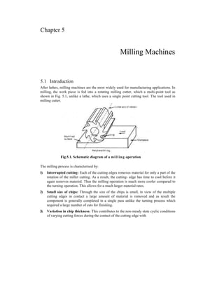
  • 1. Chapter 5 Milling Machines 5.1 Introduction After lathes, milling machines are the most widely used for manufacturing applications. In milling, the work piece is fed into a rotating milling cutter, which a multi-point tool as shown in Fig. 5.1, unlike a lathe, which uses a single point cutting tool. The tool used in milling cutter. Fig.5.1. Schematic diagram of a milling operation The milling process is characterised by: 1) Interrupted cutting: Each of the cutting edges removes material for only a part of the rotation of the miller cutting. As a result, the cutting- edge has time to cool before it again removes material. Thus the milling operation is much more cooler compared to the turning operation. This allows for a much larger material rates. 2) Small size of chips: Through the size of the chips is small, in view of the multiple cutting edges in contact a large amount of material is removed and as result the component is generally completed in a single pass unlike the turning process which required a large number of cuts for finishing. 3) Variation in chip thickness: This contributes to the non-steady state cyclic conditions of varying cutting forces during the contact of the cutting edge with
  • 2. 5.2 the chip thickness varying from zero to maximum size or vice versa. This cyclic variation of the force can excite any of the natural frequencies of the machine tool system and is harmful to the tool life and surface finish generated. A milling machine is one of the most versatile machine tools. It is adaptable for quantity production as well as in job shops and tool rooms. The versatility of milling is because of the large variety of accessories and tools available with milling machines. The typical tolerance expected from the process is about ± 0.050mm. 5.2 Types of Milling Machines To satisfy various requirements milling machines come in a number of sizes and varieties. In view of the large material removal rates milling machines come with a very rigid spindle and large power. The variety rigid spindle and large power. The varieties of milling machines available are: 1) Knee and column type a) Horizontal c) Universal b) Vertical d) Turret type. These are the general purpose-milling machines, which have a high degree of flexibility and are employed for all types of works including batch manufacturing. A large variety of attachments to improve the flexibility are available for this class of milling machines. 2) Production (Bed) type a) Simplex b) Duplex c) Triplex These machines are generally meant for regular production involving large batch sizes. The flexibility less in these machines, which is suitable for productivity enhancement. 3) Piano millers These machines are used only for very large work pieces involving table travels in meters. 4) Special type a) Rotary type b) Drum type c) Copy milling (Die sinking machine) d) Key way milling machines e) Spline shaft milling machines. These machines provided special facilities to suit specific applications that are not catered to by the other classes or milling machines.
  • 3. Milling Machines 5.3 5.3 Knee and Column Milling Machines 5.3.1 Horizontal Knee and Column Type Milling Machines The knee and column type is the most commonly used machine in view of its flexibility and easier setup. A typical machine construction is shown in Fig. 5.2 for the horizontal axis. The knee houses the feed mechanism and mounts the saddle and table. The table basically has the T-slots running along the X-axis for the purpose of work holding. The table moves along the Y-axis on the guide ways provided on the knee. The feed is provided either manually with a hand wheel or connected for automatic by the lead screw, which in turn is coupled to the main spindle drive. The knee can move up and down (Z-axis) on a dovetail provided on the column. The massive column at the back of the machine houses all the power train including the motor and the spindle gearbox. The power for feed motor is provided for the gear, box as well. Fig.5.2. Horizontal knee and Column type milling machine While the longitudinal and traverse motions are provided with automatic motion, the raising of the knee is generally made manually. The spindle is located at the top end of the column. The arbur used to amount the milling cutters is mounted in the spindle and is provided with a support on the other end to take care of the heavy cutting force by means of an overarm with bearing. As shown in Fig.5.2 the overarm extends from the column with "a rigid design. The spindle nose has the standard morse taper of the suitable size depending upon the machine size. The milling cutters are mounted on the arbour at any desired position, the rest oi the length being filled by standard hardened collars of varying widths to fix the position of the cutter. The arbour is clamped in the spindle with the help of a cjraw bar and then fixed with nuts. Milling machines are generally specified on the following basis: 1) Size of the table, which specifies the actual working area on the table and relates to the maximum size of the work piece that can be accommodated. 2) Amount of table travel which gives maximum axis movement that is possible
  • 4. 5.4 3) Horse power of the spindle, which actually specifies the power of the spindle motor used. Smaller machines may come with 1 to 3hp while the production machines may go from 5 to 50hp. 5.3.2 Vertical Knee and Column Type Milling Machine Another type of knee column milling machine is the vertical axis type. Its construction is very similar to the horizontal axis type, except for the spindle type and location. The spindle is located in the vertical direction and is suitable for using the shank mounted milling cutters such as end mills. In view of the location of the tool, the setting up of the work piece and observing the machining operation is more convenient. Another type of knee and column milling machine is flexible (Fig. 5.4) and suitable for machining complex cavities such as die cavities in tool rooms. Fig.5.3. Vertical Knee and Column Type Milling Machine Fig.5.4. Some of the milling operations normally carried out on vertical axis machine.
  • 5. Milling Machines 5.5 The vertical head is provided with a swivelling facility in horizontal direction where by the cutter axis can be swivelled. This is useful for tool rooms where more complex milling operations are carried out. 5.4 Bed Type Milling Machine In production milling machines it is desirable to increase the metal removal rates. If it is done on conventional machines by increasing the depth of cut, there is possibility I of chatter. Hence another variety of milling machines named as bed type machines are used which are made more rugged and are capable of removing more material. The rugged is obtained as a consequence of the reduction in versatility. The table in the case of bed type machines is directly mounted on the bed and is provided with only longitudinal motion. The spindle moves along with the column to provide the cutting action. Simplex machines (Fig.5.5) are the ones with only one spindle head while duplex machines have two spindles (Fig.5.6). The two spindles are located on either side of a heavy work piece and remove material from both sides simultaneously. Fig.5.5. Simplex bed type milling machine Fig.5.6. Duplex bed type milling machine
  • 6. 5.6 5.5 Universal Milling Machine It is the most versatile of all the milling machines. It is capable of performing most of the machining operations. It is similar to a plain milling machine and differs only in respect of the table movements. In a universal milling machine, in addition to three movements as incorporated in a plain milling machine, the table may have a fourth movement, i.e., the table can be swivelled in a horizontal plane. In this machine the saddle is made in two parts. The upper part with the work table fitted on it can be made free over the lower one and thus can be swivelled to any position M the horizontal plane. This special feature enables the work to be set at an angle with the cutter for milling helical and spiral flutes and grooves. 5.6 Size of Milling Machine The size of the column and knee type-milling machine is designated by the dimensions of the working surface of the table and its maximum length of longitudinal, cross and vertical travel of the table. The following are the typical size of a horizontal knee type-milling machine. Table length x width = 150 x 310mm. Power traverse = longitudinal x cross x vertical = 650 x 235 x 420mm. In addition to the above dimensions number of spindle speeds, number feeds, spindle nose taper, power available, net weight and the floor space required, etc. should also be stated in order to specify the machine fully. 5.7 Method of Cutting The milling operations are divided into two distinct methods. 5.7.1 Conventional or Up-Milling (Fig.5.7) The work is fed into the rotation of the cutter. The chip is of minimum thickness at the start of the cut and is so light that the cutter has a tendency to slide over the work until sufficient pressure is built up to bite into the work. This alternate sliding leaves marks on the milled surface. Fig.5.7. Conventional or up milling
  • 7. Milling Machines 5.7 5.7.2 Climb or Down Milling (Fig.5.8) The work moves in the same direction as the rotation of the cutter. Full engagement of the tooth is instantaneous. There is no sliding action in this type of milling and hence better surface finish is obtained. The cutter presses the work down on the work table. This is the main advantage of climb milling. But it is not recommended on light machines or on large older machines that are not in top condition or fitted with an anti-backlash device to take up play. There should not be any play in the table. Also the work and holding device must be mounted securely otherwise there would be a danger of serious accident. 5.8 Milling Operations The following are the different operations performed in a milling machine. 1) Plain milling 2) Face milling 3) Form milling 4) Straddle milling 5) Angular milling 6) Gang milling 7) Profile milling 8) End milling 9) Helical milling 10) Gear cutting 5.8.1 Plain or slab or Peripheral milling It is the operation of production of a plain, flat, horizontal surface parallel to the axis of rotation of a plain milling cutter. The two types of peripheral milling are climb or down milling and conventional or up milling. In this operation the work and the cutter are secured properly on the machine. The operation is illustrated in Fig.5.9. Fig.5.9. Slab milling Fig.5.8. Climb or Down-milling
  • 8. 5.8 5.8.2 Face Milling It is performed by a face-milling cutter rotated about an axis perpendicular to the work surface. It is carried out in a plain milling machine and the cutter is mounted on a stub arbor to produce a flat surface. The operation is illustrated in the Fig.5.10. *=? 1. Face milling Cutter. 2. Work. Fig.5.10. Face milling 5.8.3 Form Milling It is the operation of irregular contours by using cutters. The irregular contour may be convex. Concave or of any other shape. The form milling operation is illustrated in theFig.5.11. Fig.5.11. Form milling 5.8.4 Straddle Milling It is a milling operation in which a pair of side milling cutters are used for machining two parallel vertical surfaces of a work-piece simultaneously as shown in the Fig.5.12.
  • 9. Milling Machines 5.9 Fig.5.12. Straddle milling 5.8.5 Angular Milling It is the milling process, which is used for machining a flat surface at an angle, other than i right angle to the axis of the revolving cutter. The cutter used may be a single or double angle cutter depending upon whether a single surface is to be machined or two mutually inclined surfaces simultaneously as shown in the Fig.5.13. 5.8.6 Gang Milling [is the operation of machining several surfaces of a work-piece simultaneously by feeding the table against a number of cutters having same or different diameters mounted on the arbur of 3 machine. This method saves much of ma- chining time and is widely used in repetitive work. The cutting speed of a gang of cutters is calculated from the cutter of the larges t diam- eter. The operation is illustrated in Fig. 5.14. 5.8.7 Profile Milling
  • 10. Fig.5.13. Angular milling Fig.5.14. Gang milling Fig.5.15. Profile milling
  • 11. 5.5 It is the operation of reproduction of an outline of a template or complex shape of a master die on a work piece. Different cutters may be used for profile milling. An end mill is one of the most-widely used milling cutter in profile milling work as illustrated intheFig.5.15. 5.8.8 End Milling It is the operation of production of a flat surface, which may be vertical, horizontal or at an angle in reference to the table surface. The cutter used is an end mill. A vertical milling machine is most suitable for end milling operation. The Fig. 5.16 illustrates the production of slots in a work-piece using end milling cutter. 5.8.9 Helical Milling It is the operation of production of helical flutes of grooves around the periphery of a cylindrical or conical work piece. The operation is performed by swivelling the table to the required helix angle and then by rotating and feeding the work against rotary cutting edges of a milling cutter. The production of helical milling cutters, helical gears, cutting helical grooves of flutes on a drill blank or a reamer are the examples of helical-milling. 5.8.10 Gear Cutting The gear cutting operation is performed in a milling machine by using a form- relieved cutter. The cutter may be cylindrical type or end mill type. The cutter profile corresponds exactly with the tooth space of the gear. Equally spaced gear teeth are cut in a gear blank by holding the work on a universal dividing head and then indexing it. The gear cutting operation by a formed cutter is illustrated the Fig.5.17. Fig.5.16. End milling Fig.5.17. Gear cutting
  • 12. Milling Machines 5.11 5.9 Work Holding Devices A milling machine table comes with precision parallel T-slots along the longitudinal axis. The workpiece can therefore be mounted directly on the table using these T- slots. Alternatively a variety of work holding devices can be used for holding the workpiece, depending upon the type of workpiece and the type of milling to be done. Vice is the most common form of work holding devices used for holding small and regular work pieces. The vice is mounted on the table using the T-slots. A variety of vice jaws are available to suit different work piece geometries. Universal chuck is used for holding round work pieces for machining of end slots, splines, etc. Fixtures are the most common form of work holding devices used in production milling operations. They are used to reduce the set-up time and increase the locational accuracy and repeatability. For large and irregular work pieces, clamps in a variety of shapes are available as shown in Fig. 5.18. -fig.5.18. Common work holding methods in milling These clamps can be used in a number of ways. Some of the methods are shown in Fig. 5.19. However, care has to be taken to ensure that the work piece is not shifted under the action of the cutting forces. The clamping force should not be too high as this could distort the work piece.
  • 13. Fig.5.19. Work holding principles in milling 5.10 Milling Machine Attachment Some classes of milling machine attachments are used for positioning and driving the cutter by altering the cutter axis and speed, whereas other classes are used for positioning, holding and feeding the work along a specified geometric path, the following are the different attachments used on standard column and knee type milling machine. 5.10.1 Vertical Milling Attachment A vertical milling attachment can convert a horizontal milling machine into a vertical milling machine by orienting the cutting spindle axis from horizontal to vertical for performing specific operations. The attachment consist of a right angle gear box which is attached to the nose of the horizontal milling machine spindle by bolting it on the column face. The attachment with the spindle can also be swivelled at any angle other than at right angles to the table for machining angular surfaces. 5.10.2 Universal Milling Attachment It is similar to the vertical milling attachment but it has an added arrangement for swivelling the spindle about two mutually perpendicular axes. This feature of the attachment permits the cutting spindle axis to swivel at practically any angle and machine any compound angular surface of the work. The attachment is supported by the overarm is bolted to the column and enables the cutters to be operated at speeds beyond the scope of the machine. 5.10.3 Slotting Attachment The attachment is bolted on the face of the column and can also be swivelled at an angle for machining angular surfaces. The length of stroke of the ram can also be
  • 14. Milling Machines 5.13 adjusted. It converts the rotary motion of the spindle in to reciprocating motion of the ram by means of an eccentric ortcrank housed within the attachment. Thus a milling machine can be converted in to a slotter by accepting a single point slotter tool at the bottom end of the ram and is conveniently used for cutting internal or external keyways, splines, etc. 5.10.4 Universal Spiral milling Attachment The universal spiral milling attachment may be used in a plain milling machine or in a universal milling machine for cutting a spiral grooves on a cylindrical work piece. The attachment is bolted on the face of the column and its spindle head may be swivelled in a vertical or horizontal plane. While using on a plain milling machine, the cutter mounted on the attachment may be swivelled to the required helix angle for cutting a spiral similar to the swivelling of the table of a universal milling machine. 5.10.5 Rack Milling Attachment A rack milling attachment is used for cutting rack teeth on a job mounted on the table. The attachment consisting of a gear train enables the spindle axis to be at right angles to the machine spindle in a horizontal plane. The successive rack teeth are cut by using a rack indexing attachment. The slanted rack teeth or a skew rack may be machined when the attachment is mounted on a universal milling machine where the table may be swivelled to the required helix angle. 5.10.6 Circular Milling Attachment A circular milling attachment is bolted on the top of the machine table. It. provides rotary motion to the work piece in addition to the longitudinal cross and vertical movements of the table. The attachment consist of a circular table having T-slots mounted on a graduated base. The circular table may be rotated by hand, and in special cases by power by linking the rotary table driving mechanism with the machine lead screw. The surface of any profile of a work piece can be generated by combining three or four moments of the table and rotary movement of the attachments. In some of the circular milling attachments an index plate is provided on the horizontal worm shaft for milling equally spaced slots or grooves on the periphery of a work piece. 5.10.7 Dividing Head Attachment A dividing head attachment is bolted on the machined table. The work may be mounted on a chuck fitted on the dividing head spindle or may be supported between a live and a dead centre. The dead centre is mounted on a footstock. The attachment is principally used for dividing the periphery of a work piece in equal number of divisions for machining equally spaced slots or grooves. The worm and worm gear driving mechanism of the attachment can be linked with the table lead screw for cutting equally spaced helical grooves on the periphery of a cylindrical work piece. I
  • 15. 5.14 5.11 Milling Cutters The milling cutter is a multi-point revolving tool. It has a cylindrical body and rotates on its one axis. It is provided with equally spaced teeth, which engages the work piece intermittently and remove material by relative movement of the work piece and the cutter. The teeth of the milling cutter can be straight or parallel to the axis of the rotation or at an angle known as "helix angle". The helix angle may be right hand or left hand and the direction of rotation of the cutter for performing the cutting operation depends on this helix angle. Further, a milling cutter may be made of single piece (solid cutter) or having the cutting portion welded to a tough shank (tipped solid cutter) or having removable cutting teeth inserted in a solid body (inserted teeth cutter). The milling cutters are classified according to their use as 1) Standard milling cutters 2) Special milling cutters. 5.12 Standard Milling Cutters There are many different types of standard milling cutters. They are further classified according to the shape of teeth as a) Plain milling cutters b) Side milling cutters c) Metal slitting cutters d) Angular milling cutters e) End milling cutters f) T-slot milling cutters g) Wood-ruff key slot milling cutter h) Fly cutter i) Formed cutters 5.12.1 Plain Milling Cutters These cutters have straight or helical teeth cut on the periphery of a cylindrical surface. These are used to mill flat surfaces parallel to the cutter axis. If the cutter is too long it is then called as slab milling cutter. The plain milling cutters are of different categories such as light duty plain milling cutter. These cutters are available in diameters from 16 to 160mm and width of the cutters range from 20 to 160mm. The Fig. 5.20 illustrates a slab-milling cutter. These cutters are made to have either fine pitch or coarse pitch. The fine pitch teeth cutters are used for light and finishing work and called as light duty cutters. The coarse pitch teeth cutters are called as heavy duty slab milling cutters. They carry less number of teeth having a steep helix angle. These are commonly used where heavy cuts are to be employed since they are capable of removing more material with less power consumption.
  • 16. Fig.5.20. Slab milling Cutter The Fig. 5.21 illustrates a helical plain milling cutter with coarse pitch. The helix angle of the teeth of the cutter ranges from 45° to 60°. This cuter is useful in profile milling work due to smooth cutting action and is adopted for taking light cuts. Fig.5.21. Helical milling cutter 5.12.2 Side Milling Cutters These cutters have teeth on the periphery and also on one or both sides of the tool. These are usually saw tooth shape as shown in the Fig. 5.22. They are available in the following types. Fig.5.22. Side milling Cutter 5.12.2.1 Plain Side Milling Cutters These have teeth cut on periphery and on both sides of the tool. Their width very from 4.75 to 25.4mm and diameters up to 200mm. Two or more of these cutters may be mounted on the arbor and the different faces of the work piece may be machined simultaneously. Milling Machines 5.15
  • 17. 5.16 5.12.2.2 Staggered Teeth Side Milling Cutters These cutters are mostly used for milling deep slots as. They have teeth with alternate helix. 5.12.2.3 Half Side Milling Cutter These cutter are available as left or right hand cutters having teeth on their periphery and on any one side. These cutters are used in straddle milling. 5.12.2.4 Inter Locking Side Milling Cutter These cutters are similar in design to the side milling cutters but are used as a unit consisting of two cutters joined together such that their teeth interlock. These cutters can be adjusted to the required width by inserting spacers between the cutters. These cutters are used for milling a slot of standard width to the exact size. They can also be used in gang milling. 5.12.3 Metal Slitting Cutters These cutters resemble a plain milling cutter or a side-milling cutter in appearance but they are of very small width. These are used for cutting-off and slotting operations and are somewhat similar to the circular saw blades as shown in the Fig.5.23. Fig.5.23. Metal Slitting Saw The different types of metal slitting cutters (saw) are described below. 5.12.3.1 Plain Metal Slitting Cutter These cutters teeth of saw tooth with both sides slightly concave to provide clearance while cutting. They are available in width up to 4.7mm and are used for fine slitting operation. 5.12.3.2 Staggered Teeth Metal Slitting Cutters These cutters resemble a staggered teeth side-milling cutter. These cutters have to their teeth staged at the periphery with alternate helix. But the width of the cutter is limited to 65 to 7mm. These cutters are used for heavy sawing in steel. 5.12.3.3 Side Teeth Slitting Cutters These cutters are used for cutting off wider material or for making a deep slot.
  • 18. Milling Machines 5.17 5.12.4 Angular Milling Cutters These cutters may be single or double angle cutters for milling standard surfaces at 45° to 60°. There are two types of angular milling cutters that are in use. 5.12.4.1 Single Angular Milling Cutter As shown in the Fig. 5.24 the single angle cutters have their teeth either only on angular face or on both the angular face and side. The latter type enables milling of both the flanks of the included angular groove simultaneously. Fig.5.24. Single Angular Milling 5.12.4.2 Double Angular Milling Cutters These cutters differ from the single angular cutters in that they have two angular faces which join together to form V-shaped teeth as shown in the Fig.5.25. This included angle is either 45°, 60° or 90° and the angle of both the faces of the cutter is not necessary equal. These cutters are mainly used for spiral grooves. Fig.5.25. Double angular milling cutters 5.12.5 End Milling Cutters The cutters have cutting teeth on the end' as well as on the periphery of the cutter. These are of two types, (i) Those having the shank known as shank type cutters and (ii) Others, which do not have the shank, called as shell type cutters. In shank type cutters the cutter body works as a shank where as in shell type cutters the body and shank are separate.
  • 19. 5.18 Shank type and milling cutters are of two types, (i) Taper shank milling cutter (ii) Straight stand end- milling cutters. 5.12.5.1 Taper shank End Milling Cutter These cutters have teeth on end of the taper shank and the tang is like the drill spindle to fit in a collet. 5.12.5.2 Straight Shank Milling Cutter These cutters have a straight cylindrical shank. They can have teeth at one or both ends. Their teeth may be straight or helical. 5.12.5.3 Shell End Milling Cutter These cutters are made in larger sizes than solid mills. These cutters have a hole at one end and a slot milled at the other end to fit the tang on the arbor. The cutter is held on the arbor by a_cap screw. These cutters are used for facing, slotting and side milling operations. A type of shell end milling cutter is shown in the Fig.5.26. Fig.5.26. Shell end milling cutter 5.12.6 T-slot Milling Cutter It is a single operation Cutter, which is used only for cutting T-slots. In smaller sizes the shank is made integral with the cutter as shown in the Fig.5.27. The large size cutter are mounted on a separate shank. The teeth are provided on the periphery as well as on both sides of the cutters. Fig.5.27. T-slot milling cutter 5.12.7 Wood Ruff Key Slot Milling Cutter It is a small standard cutter similar in construction to a thin small diameter plain milling cutter. It is intended for the production of woodruff key slots. This cutter is provided with a shank and may have straight or stagged teeth as shown in the Fig.5.28.
  • 20. Fig.5.28. Wood reff key slot milling cutter 5.12.8 Fly Cutter It is a single point tool. It is either mounted on a cylindrical body held in a stab orbor or held in a bar exactly in the same way as a boring bar as shown in the Fig.5.29. Fig.5.29. Fly Cutter The cutting edge may be formed to reproduce contoured surface. It is generally used for experimental purpose when the standard cutters are not available. 5.12.9 Formed Cutters These cutters have irregular profile on the cutting edge in order to generate an irregular out line of the work. The different types of standard formed cutters are 1) Convex milling cutter and 2) Concave milling cutter. 5.12.9.1 Convex Milling Cutter This cutter has teeth curved outwards on the circumferential surface to form the contour of a semicircle. The produces a concave semicircular surface on a work piece. The diameter of the cutter ranges from 50 to 125mm and the radius of the semicircle varies from 1.6 to 20mm. The Fig. 5.30 illustrates a convex milling cutter. Milling Machines 5.19
  • 21. Fig. 5.30. Convex milling cutter 5.12.9.2 Concave Milling Cutter This type of cutter has teeth curved in wards on the circumferential surfaces to form the contour of a semicircle. The concave milling cutter produces a convex semicircular surface on a work piece. The diameter of the cutter ranges from 56 to 15mm and the radius of the semicircle varies from 1.5 to 20mm. The Fig.5.31 illustrates a concave milling cutter. Fig.5.31. Concave milling Cutter 5.13 Cutters Materials The milling cutters may be made of 1) High speed steel 2) Super high speed steel 3) Non-ferrous cast alloys or cemented carbide tipped. In normal work high speed steel cutters are more common in production shops. Carbide tipped cutters are used as they last long and yield high production. The tips of carbide are brazed on the high carbon steel body of the cutter. 5,13.1 Teeth Forms of a Milling Cutter A milling cutter have teeth of three forms (i) Saw tooth
  • 22. Milling Machines 5.21 (ii) Form tooth and (iii) Inserted tooth. 5.13.2 Nomenclature of a Milling Cutter |The nomenclature of a milling cutter is illustrated in the Fig. 5.32. Fig.5.32. Nomenclature of a milling cutter (i) Body of Cutter The part of the cutter left after exclusion of the teeth and the portion to which the teeth are attached. (ii) Cutting Edge The edge formed by the intersection of the teeth and the circular land or the surface left by the provision of primary clearance. (iii) Face The portion of the gash adjacent to the cutting edge on, which the chip impinges as its cut from the box. (iv) Fillet The curved surface at the bottom of the gash which joins the face of one tooth to the back of the tooth immediately a-head. (v) Gash The chip space between the back of one tooth and the face of the next tooth. (vi) Land The part of the back of the tooth adjacent to the cutting edge, which is relived to avoid interference between the surface being machined and cutter.
  • 23. 5.22 (vii) Lead The axial advance of the helix of the cutting edge in one complete revolution of the cutter. (viii) Outside Diameter The diameter of the circle passing through the peripheral cutting edge. (ix) Root Diameter The diameter of the circle passing through the bottom of the fillet. 5.14 Cutter Angles 5.14.1 Relief Angle The angle in a plane perpendicular to the axis, which is the angle between the land of the tooth and tlje tangent to the out side diameter of the cutter at the cutting edge of that tooth. 5.14.2 Primary Clearance Angle The angle formed by the back of the tooth with a line drawn tangent to the periphery of the cutter at the cutting edge. 5.14.3 Secondary Clearance Angle The angle formed by the secondary clearance surface of the tooth with a line drawn tangent to the periphery of the cuter of the cutting edge. 5.14.4 Rake Angle The angle measured in the diameter plane between the face of the tooth and radial line passing through the tooth cutting edge. It may be positive, negative or zero. 5.14.5 Axial Rake Angle The angle between the line of peripheral cutting edge and the axis of the cutter when looking radially at the point of intersection. 5.14.6 Lip Angle The included angle between the land and, the face of tooth or alternately the angle between the tangent to the back at the cutting edge and the face of the teeth. 5.14.7 Helix Angle The cutting edge angle, which a helical cutting edge makes with a plane containing the axis of a cylindrical cutter.
  • 24. Milling Machines 5.23 5.15 Indexing In many milling operations, the job is required to be rotated correct to the fractions on minutes, such as in milling gear teeth, splines, grooves slots, hexagonal or square heads, of bolts and nuts, etc. the operation of rotating the job through the required angle between the two successive cuts is called indexing. This angle between the two successive cuts is called indexing. This is accomplished with the help of the indexing head or dividing head. 5.16 Methods of Indexing The principle methods of indexing are as follows. 1) Direct indexing 2) Simple or plain indexing. 3) Compound indexing 4) Differential indexing 5) Angular indexing. 5.16.1 Direct Indexing Direct indexing is accomplished by using the index plate attached to the work spindle. The index plate has 24 divisions, and can be divided in to 2, 3, 4, 6, 8 and 12 equal parts directly. It is engaged by a plunger pin on the head, and can be turned the required amount by hand. The use of worm and worm wheel is avoided. This method of indexing limited only to those divisions that are factor or 24. It is a quick method of indexing and used when only a few cuts are required in a revolution. 5.16.2 Simple or Plain Indexing It is accomplished by turning the crank a number of turn to rotate the work the desired amount, the indexing plate being held in a fixed position. Different index plates with varying number of holes are used to increase the range of indexing. 1 With a ratio of 40 to 1, on revolution of the crank will rotate the work -—of a 40 revolution. Hence to cut a gear with 40 teeth the crank would be locked the plate by the index pin and a cut would be made. After one cut, the handle would be turned one revolution and another cut taken and so on. To cut a gear with 20 teeth would require 2 turns of the handle. The cut 8 flutes on a reamer, 5turns of the handle would be made. As long as the number of cuts to be taken is factor of 40, it is a simple matter to calculate the number of handle turns. By following these simple calculations, we conclude the following rule:
  • 25. If 24 teeth are to be cut on a gear blank, then First, select a circle on the index plate that is divisible by 3. If a 24-space circle is available, then the worm is to be rotated by the handle through one complete rotation and 16 spaces of 24 space circle. In setting the arms, space and not holes should be counted. Fig. 5.33. Simple indexing mechanism 5.16.3 Compound Indexing It is accomplished on the same principle as the simple indexing, but the only difference is that is used two different circles of one plate and hence also sometimes referred to as hit and trial method. The principle of compound indexing is to obtain the required division by two stages. (i) By rotating the crank or handle in useual way keeping the index plate fixed. (ii) By releasing the back-pin and then rotating the index plate with the handle. Let 27 teeth are to be cut on a gear blank, Thus, for each tooth, rotate the worm by 12 spaces of 18 space circle with the help of crank and then rotate the index plate by 22 spaces of 27 space circle. 5.24 s
  • 26. Milling Machines 5.25 5.16.4 Differential Indexing Plain indexing is sometimes limited to a certain extent due to the available number of index plates with different space circles. If the work is to be turned an amount that cannot be obtained by plain indexing the differential indexing is adopted. In such a case, the index plate is unlocked and connected to a train of gears, which receive their motion from the worm gear spindle. As the handle is turned, the index plate also turns, but at a different rate. Its movement depends on these gear used to drive it. After the gears are set up, the operation is similar to simple indexing. By the method of indexing, the work may be rotated by any fraction of revolution with the usual indexing plates. The following relation is used for calculating the necessary gears to be placed between the spindle and the worm shaft. and a crank movement Where N = no. of divisions to be indexed and P = a no. of slightly more or less than N. The equation (5.1) gives the gear ratio to be placed on the spindle (driver) and the worm shaft (Driven). The arrangement of gears may be simple or compound train depending upon the suitability. If (n-N) is positive, then rotate the index plate in the direction in which crank is rotated. If it is negative, then rotate the index plate in opposite direction to that of the crank. 5.16.5 Angular Indexing Sometimes the work is to be rotated through a certain angle instead of rotating it through certain division of its periphery. Angular indexing gives the rotation of work through certain angle. Since the crank and spindle ratio is 40:1 by moving the crank 1 through one revolution, the spindle or the work move through —lh of revolution. i.e. -rr- = 9 degrees. Example 5.1 Find the indexing movement need for milling the sides of (a) square nut (b) hexagonal nut. Solution (a) using the relation,
  • 27. /0.34 5.17 Cutting Speed, Feed and Depth of cut 5.17.1 Cutting speed The speed of milling cutter is its peripheral linear speed resulting from rotation. It is expressed in meters per minute. The cutting speed can be derived from the formula: where, V = The cutting speed in m per min d = The diameter of the cutter in mm. n = The cutter speed in r.p.m. The spindle speed of a machine is selected to give the desired peripheral speed of the cutter. The average values of cutting speed for different materials are given in table 5.17.2 Feed The feed in a milling machine is defined as the rate with which the work piece advances under the cutter. The feed is expressed in a milling machine by the following three different methods. 1) Feed Per Tooth (Sz) The feed per tooth is defined by the distance the work advances in the time between engagement by the two sucessive teeth. It is expressed in millimeters per tooth of the cutter. 2) Feed Per Cutter Revolution (Srev) The feed per cutter revolution is the distance the work advances in the time when the cutter turns through one complete revolution. It is expressed in millimeters per revolution of the cutter. 3) Feed Per Minute (SJ The feed per minute is defined by the distance the work advances in one minute. It is expressed in millimeters per minute. The feed per tooth, the feed per cuttter revolution, and the feed per minute are related by the formula which is given below. Sm = n x Srev = Sz x Z x n .........................................(5.3)
  • 28. Milling Mach ines 5.35 where, Z = number of teeth in the cutter and n = the cutter speed in r.p.m The average values of feed are given in Table. Table: 5.1 Averge cutting speed and feed of different materials. Face milling Tool steel h.s.s Tool steel h.s.s Work material Cuttin 8 speed Feed mm/ min Cuttin g speed Feed mm/m in Cuttin g speed Feed mm/m in Cuttin g speed Feed mm/min Mild steel 37 kg/mm2 . 7.2-18 150-15 24-42 300-30 7.2-18 50-10 18-36 80-15 Grey cast iron 6-15 250-15 18-36 250-25 6-15 60-20 15-30 100-30 Mild steel 50 kg/mm2 7.2-15 150-15 18-36 250-25 7.2-15 40-10 15-30 70-15 Bronze or brass 18-36 200-20 42-72 300-30 18-36 100-20 36-60 180-30 Cutting speed is in m/min. 5.17.3 Depth of cut The depth of cut in milling is the thickness of the material removed in one pass of the work under the cutter. It is the perpendicular distance measured between the original and final surface of the work piece, and is expressed in min, 5.18 Calculation of Machining Time The time required to mill a surface for any operation can be calculated from the formula: Where T = The time required to complete the cut in minutes. L = The length of the table travel to complete the cut in mm. Sz = The feed per tooth in mm Z = The number of teeth in the cutter n = The r.p.m. of the cutter.
  • 29. 5.36 In Fig. 5.37 the length of the table travel 'L' is composed of two parts: the length of the work 'C and the approach length A' is the distance through which the cutter must be moved before the full depth of cut is reached. Fig.5.37. Approach length for plain milling cutter. Approach length for Plain Milling Cutter The approach A for a plain milling cutter can be calculated from the equation: or where, A = The approach in mm. B = The depth of cut in mm D = The diameter of the cutter in mm. Approach length for face milling cutter Referring to the Fig.5.38 the approach length for a face milling cutter can be calculated from the equation. where A = The approach length in mm D = The diameter of the cutter. t
  • 30. Milling Machines 5.37 B = The width of the work Putting the value of 'C in the equation Fig.5.38. Approach length for face milling cutter