SlideShare a Scribd company logo
1 of 29
Maintenance Of Lathe Machine
Government Polytechnic, Khamgaon Page 1
INTRODUCTION
A lathe is a machine tool that rotates the workpiece on its axis to perform various
operations such as cutting, sanding, knurling, drilling, or deformation, facing,
turning, with tools that are applied to the workpiece to create an object with
symmetry about an axis of rotation.
Lathe are used in woodturning, metalworking, metal spinning, thermal spraying ,
parts reclamation, and glassworking. Lathes can be used to shape pottery, the
best known design being the potters wheel. Most suitably equipped metalworking
lathe can also be used to produce most solids of revolution, plain surfaces and
screw threads and helices. Ornamental lathes can produce three dimensional
solids of incredible complexity. The workpiece is usually held in place by either
one or two centres, at least one of which can typically be moved horizontally to
accommodate varying workpiece lengths. Other work-holding methods include
clamping the work about the axis of rotation using a chuck or collet, or to a
faceplate, using clamps or dogs.
Fig no.1 Lathe machine
Maintenance Of Lathe Machine
Government Polytechnic, Khamgaon Page 2
HISTORY
Lathes were developed as early as the 15th century and were known as "bow"
lathes. The operator rotated the workpiece by drawing a bow back and forth,
either by hand or with the use of a foot treadle. Next came Bessons lathe in
1568, which was driven by a cord passing over a pulley above the machine. This
in turn drove two other pulleys on the same shaft which rotated the workpiece
and a crude, wooden lead screw, which in turn allowed the operator to remove
metal from the piece being machined. The screw cutting lathe originates in the
17th century. Development and advancements have continued and today we
have sophisticated computerized controlled lathes.
Lathes have allowed man to reshape, machine and manufacture many precision
cylindrical components made of various types of metal, wood, plastics, and other
materials. Without the lathe, man would still be trying to produce cylindrical
components in some crude fashion or another. However, because of advanced
technology, the lathe has allowed man to become an important asset in
developing and machining many precision components needed to operate and
function in many areas of our industrial complex.
Fig no 2. Olden Type of Lathe Machine
Maintenance Of Lathe Machine
Government Polytechnic, Khamgaon Page 3
TYPES OF LATHE
1) Engine Lathes
These are probably the most popular among the lathe machines. In fact, no
machine soft is seen without this type of lathe. The good thing about engine lathe
is that it can be used in various materials, asides from metal. Moreover, the setup
of these machines is so simple that they are easier to use. Its main components
include the bed, headstock and tailstock. These engine lathes can be adjusted to
variable speed for the accommodation of a wide scope of work. In addition, these
lathe come in various sizes.
2) Turret Lathes
These types of lathes are used for machining single workpieces sequentially.
This means that several operations are needed to be performed on a single
workpiece. With thw turret lathes, sequential operations can be done on the
workpiece, eliminating errors in work alignment. With this setup, machining is
done more efficiently. Correspondingly, time is saved because there is no need to
remove and transfer the workpiece to another machine anymore.
3) Special Purpose Lathes
As name implies, these lathes are used for special purpose such as heavy duty
production of identical parts. In addition, these lathe also perform specific
functions that cannot be performed by the standard lathes. Some examples of
special purpose lathes include the bench type jeweler’s lathes, automatic lathes,
crank shaft lathes, duplicating lathes, multispindle lathes, breakdrum lathes and
production lathes among others.
Maintenance Of Lathe Machine
Government Polytechnic, Khamgaon Page 4
BASIC PARTS OF LATHE
1) Bed and Ways.
The bed is the base for the working parts of the lathe. The main feature of the
bed is the ways which are formed on the bed's upper surface and which run the
full length of the lathe. The tailstock and carriage slide on the ways in alignment
with the headstock. The headstock is normally permanently bolted at one end (at
the operator's left). The ways are accurately machined parallel to the axis of the
spindle and to each other. The V-ways are guides that allow the carriage and the
tailstock to move over them only in their longitudinal direction. The flat way takes
most of the downward thrust. The carriage slides on the outboard V-ways which,
because they are parallel to the V-ways, keep the carriage in alignment with the
headstock and tailstock at all times. This is an absolute necessity if accurate
lathe work is to be done. Some lathe beds have two V-ways and two flat ways,
while others have four V-ways. For satisfactory performance of a lathe, the ways
must be kept in good condition. A common fault of careless machinists is to use
the bed as an anvil for driving arbors or as a shelf for hammers, wrenches, and
chucks. Never allow anything to strike the ways or damage their finished surfaces
in any way. Keep them free of chips. Wipe them off daily with an oiled cloth to
help preserve their polished surface.
Fig no. 3 Bed and guide ways of Lathe machine
Maintenance Of Lathe Machine
Government Polytechnic, Khamgaon Page 5
2) Headstock
The headstock carries the head spindle and the mechanism for driving it. In the
belt-driven type headstock, the driving mechanism consists merely of a cone
pulley that drives the spindle directly or through the back gears. When the spindle
is driven directly, it rotates the cone pulley. When the spindle is driven through
the back gears, it rotates more slowly than the cone pulley, which in this case
turns freely on the spindle. Thus two speeds are available with each position of
the belt on the cone; if the cone pulley has four steps, eight spindle speeds are
available. The geared headstock shown in figure is more complicated but more
convenient to operate, because the speed is changed by changing or by shifting
the gears. This headstock is similar to an automobile transmission except that it
has more gear-shift combinations and, therefore, has a greater number of speed
changes. A speed index plate, attached to the headstock, indicates the lever
positions for the different spindle speeds. To avoid damage to the gear teeth, the
lathe is always stopped before the gears are shifted.
Figure shows the interior of a typical geared headstock that has 16 different
spindle speeds. The driving pulley at the left is driven at a constant speed by a
motor located under the headstock. Various combinations of gears in the
headstock transmit power from the drive shaft to the spindle through an
intermediate shaft.
Fig no. 4 Headstock
Maintenance Of Lathe Machine
Government Polytechnic, Khamgaon Page 6
3) Tailstock
The primary purpose of the tailstock is to hold the dead center to support one end
of the work being machined between centers. However, it can also be used to
hold live centers, tapered shank drills, reamers, and drill chucks. The tailstock
moves on the ways along the length of the bed to accommodate work of varying
lengths. It can be clamped in the desired position by the tailstock clamping nut.
The dead center is held in a tapered hole (bored to a Morse taper) in the tailstock
spindle. The spindle is moved back and forth in the tailstock barrel for longitudinal
adjustment. The handwheel is turned which turns the spindle-adjusting screw in a
tapped hole in the spindle. The spindle is kept from revolving by a key that fits a
spline, or keyway, cut along the bottom of the spindle. The tailstock body is made
in two parts. The bottom, or base, is fitted to the ways; the top can move laterally
on its base. The lateral movement can be closely adjusted by setscrews. Zero
marks inscribed on the base and top indicate the center position and provide a
way to measure set over for taper turning. Before inserting a dead center, a drill,
or a reamer into the spindle, carefully clean the tapered shank and wipe out the
tapered hole of the spindle. After a drill or reamer is placed into the tapered hole
of the spindle, make sure that the tool will not turn or revolve. If the tool is allowed
to revolve, it will score the tapered hole and destroy its accuracy. The spindle of
the tailstock is engraved with graduations which help in determining the depth of
a cut when a piece is drilled or reamed.
Fig no. 5 Tailstock
Maintenance Of Lathe Machine
Government Polytechnic, Khamgaon Page 7
4) Carriage
The carriage carries the crossfeed slide and the compound rest whichin turn
carries the cutting tool in the toolpost. The carriage slides on the ways along the
bed. The wings of the H-shaped saddle contain the bearing surfaces which are
fitted to the Vways of the bed. The cross piece is machined to form a dovetail for
the crossfeed slide. The crossfeed slide is closely fitted to the dovetail and has a
tapered gib which fits between the carriage. dovetail and the matching dovetail of
the cross feed slide. The gib permits small adjustments to remove any looseness
between the two parts. The slide is securely bolted to the crossfeed nut which
moves back and forth when the crossfeed screw is turned by the handle. The
micrometer dial on the crossfeed handle is graduated to permit accurate feed.
Depending on the manufacturer of the lathe, the dial may be graduated so that
each division represents a 1 to 1 ratio. The compound rest is mounted on top of
the crossfeed slide. The carriage has T-slots or tapped holes for clamping work
for boring or milling operations. When the lathe is used in this manner, the
carriage movement feeds the work to the cutting tool which is revolved by the
headstock spindle. The carriage can be locked in any position on the bed by
tightening the carriage clamp screw. The clamp screw is to be used only when
doing work for which longitudinal feed is not required, such as facing or cutting off
stock. Normally, the carriage clamp is kept in the released position. The carriage
is always moved by hand to make sure that it is free before the automatic feed is
applied. The carriage consists of the tool post which carries the tool used in lathe
machine.
Fig no. 6 Carriage
Maintenance Of Lathe Machine
Government Polytechnic, Khamgaon Page 8
5) Lead screw
The lead screw is used for thread cutting. Along its length are accurately cut
Acme threads which engage the threads of the half-nuts in the apron when the
half-nuts are clamped over it. When the lead screw turns inside the closed half-
nuts, the carriage moves along the ways a distance equal to the lead of the
thread in each revolution of the lead screw. Since the lead screw is connected to
the spindle through a gear train the lead screw rotates with the spindle.
Whenever the half-nuts are engaged, the longitudinal movement of the carriage
is directly controlled by the spindle rotation. The cutting tool is moved a definite
distance along the work for each revolution of the spindle. The ratio of the
threads per inch of the thread being cut and the thread of the lead screw is the
same as the ratio of the speeds of the spindle and the lead screw. For example: If
the lead screw and spindle turn at the same speed, the number of threads per
inch being cut is the same as the number of threads per inch of the lead screw. If
the spindle turns twice as fast as the lead screw, the number of threads being cut
is twice the number of threads per inch of the lead screw. The ratio of the threads
per inch of the thread being cut and the thread of the lead screw is the same as
the ratio of the speeds of the spindle and the lead screw. For example: If the lead
screw and spindle turn at the same speed, the number of threads per inch being
cut is the same as the number of threads per inch of the lead screw. If the spindle
turns twice as fast as the lead screw, the number of threads being cut is twice the
number of threads per inch of the lead screw.
Fig no 7 Lead screw
Maintenance Of Lathe Machine
Government Polytechnic, Khamgaon Page 9
6) Quick Change GearMechanism
To do away with the inconvenience and loss of time involved in removing and
replacing change gears, most modern lathes have a selfcontained change gear
mechanism, commonly called a "quick-change gear box."
There are a number of types used on different types of lathes, but they are all
similar in principle. The quick-change gear box mechanism consists of a cone-
shaped group of change gears. One can instantly connect any single gear in the
gear train by a sliding tumbler gear controlled by a lever. The cone of gears is
keyed to a shaft which drives the lead screw (or feed rod) directly or through an
intermediate shaft. Each gear in the cluster has a different number of teeth and
hence produces a different ratio when connected in the train. Sliding gears also
produce other changes in the gear train to increase the number of different ratios
one can get with the cone of change gears. All changes are made by shifting the
appropriate levers or knobs. An index plate or chart mounted on the gear box
indicates the position in which to place the levers to obtain the necessary gear
ratio to cut the threads or produce the feed desired. Figure depicts the rear view
of one type of gear box. The splined shaft turns with gear G, which is driven by
the spindle through the main gear train mounted on the end of the lathe. Shaft F
in turn drives shaft H through the tumbler gear T, which can be engaged with any
one of the cluster of eight different size gears on shaft H by means of the lever C.
Shaft H drives shaft J through a double-clutch gear, which takes the drive through
one of three gears, depending on the position of lever B (right, center or left).
Shaft J drives the lead screw through gear L. Either the lead screw or the feed
rod can he connected to the final driveshaft of the gear box by engaging the
appropriate gears. The lathe gear box shown in figure has no feed rod. Twenty-
four different gear ratios are provided by the quick-change gear box. The lower
lever has eight positions, each of which places a different gear in the gear train
and hence produces eight different gear ratios. The three positions of the upper
level produce three different gear ratios for each of the 8 changes obtained with
the lower lever, thus making 24 combinations in the box alone. This range can be
doubled by using the sliding compound gear which provides a high- and low-gear
ratio in the main gear train. This gives two ratios for every combination obtainable
in the box, 48 combinations in all.
Maintenance Of Lathe Machine
Government Polytechnic, Khamgaon Page 10
LATHE ACCESSORIES
The lathe machines are provided with different accessories. Lathe accessories
are used for holding and supporting the work and holding the tool. The following
are the accessories employed with the lathe.
1) Centre
The lathe centres are used for supporting the work during turning operations.
There are two centres i.e. live centre and dead centre. The workpiece is held
between these two centres.
2) Chuck
A chuck is one of the most important devices for holding and rotating the piece of
the work on lathe. It is attached to the headstock spindle by the means of bolts
with back plates and set scews on the spindle nose.
Types of chucks:
 Three jaw chuck.
 Four jaw chuck.
 Combination chuck.
 Collect chuck.
 Spindle chuck.
 Magnetic chuck.
 Air operated chuck.
3) Face plates
It is a cast iron circular disc, having a threaded hole a its centre so that it can be
screwed on the threaded nose of the spindle. There are number of holes and
slots provided on this plate. It is used for holding the work, which cannot be held
between centres or on the chuck. The work is held with the help of clamping
plates and bolts.
Maintenance Of Lathe Machine
Government Polytechnic, Khamgaon Page 11
4) Driving plate or catch plate
A catch plate is plane disc made up of cast iron or steel. It has a central boss and
catch pin projecting from it. It is screwed on the threaded nose of headstock
spindle. It is used for driving the work with the help of projecting pin on it, with the
dog or carries clamp to work while turning the work between the centres.
5) Angle plate
Angle plate is a “L” shaped cast iron plate. Two faces of the plates are at right
angle and having slots for clamping face plate on its surface. It is used for holding
the work, which is not possible to mount directly on the face plate.
6) Mandrel
Mandrel is a device used for holding a hollow workpiece that has been previously
drilled or bored. It is the solid shaft made up of high carbon steel. It is mounted
between centres and work revolves with it. It is driven by the driving plate and
carrier.
Different types of mandrel are:
 Plain mandrel.
 Collar mandrel.
 Cone mandrel.
 Expansion mandrel.
 Step mandrel.
7) Rest
It is the device which is used to support long slender jobs at an intermediate point
to prevent it from bending, due to its own weight and vibration caused by cutting
force acting on it. Rest will be used when length of workpiece is more than 12
times its diameter.
Common types of rest used are:
 Steady rest.
 Follower rest.
Maintenance Of Lathe Machine
Government Polytechnic, Khamgaon Page 12
OPERATIONS PERFORMED ON LATHE MACHINE
1) Facing
Facing is the square finishing of the ends of the workpiece and is often used to
bring the piece to a specified length. In facing operations, the cutter bit does not
traverse laterally (left or right) but cuts inward or outward from the axis of the
piece. Facing of the ends is usually performed before turning operations.
2) Straight turning
Straight turning may he performed upon a workpiece supported in a chuck, but
the majority of workpieces turned on an engine lathe are turned between centers.
Turning is the removal of metal from the external surface of cylindrical
workpieces using various types of cutter toolbits.
3) Finish turning
When the workpiece has been rough turned to within about 1/32 inch of the
finished size, take a finishing cut. A fine feed, the proper lubricant, and above all
a keen-edged toolbit are necessary to produce a smooth finish. Measure carefully
to be sure that the workpiece is being machined to the proper dimension. The
lathe should be stopped whenever measurements are to be made.
4) Parting
One of the methods of cutting off a piece of stock while it is held in a lathe is a
process called parting. This process uses a specially shaped tool with a cutting
edge similar to that of a square nose cutting tool. The parting tool is fed into the
rotating workpiece, perpendicular to its axis, cutting a progressively deeper
groove as the workpiece rotates. When the cutting edge of the tool gets to the
center of the workpiece being parted, the workpiece drops off. Parting is used to
cut off parts that have already been machined in the lathe, or to cut tubing and
bar stock to their required lengths.
Maintenance Of Lathe Machine
Government Polytechnic, Khamgaon Page 13
5) Taper turning
In ordinary straight turning, the cutting tool moves along a line parallel to the axis
of the work, causing the finished job to be the same diameter throughout.
However, when cutting a taper, the tool moves at an angle to the axis of the work,
producing a taper. Therefore, to turn a taper, the work must either be mounted in
a lathe so that the axis upon which it turns is at an angle to the axis of the lathe,
or cause the cutting tool to move at an angle to the axis of the lathe.
6) Chamfering
Chamfering is operation of producing a bevel shape finish at the end of
workpiece. Chamfering is done for removing burrs and for protecting the end from
getting damaged. Chamfering is essential after thread cutting operation. It may
be performed after turning, knurling, boring, drilling etc.
7) Knurling
Knurling is the operation of producing a diomand shaped pattern on the surface
of the workpiece. The purpose of knurling is to provide an effective gripping
surface on a workpiece to prevent it from slipping when operated by hand.
Knurling is provided on handle of the machine and gauges. It is done by the
knurling tool, which consists of hardened steel rollers in a holder. The rollers have
a teeth cut in a definite pattern on their surface. Knurling is done at very low
speed. The feed during knurling varies from 1mm to 2 mm per revolution.
8) Drilling
Drilling is the operation of producing a cylindrical hole by removing metal by the
rotating edge of the cutting tool called as drill. The workpiece is held in chuck and
drill tool is fitted in tailstock barrel. The drill is fed to workpiece by rotating hand
wheel of tailstock. The speed of feed during drilling is 25% less than normal
speed.
Maintenance Of Lathe Machine
Government Polytechnic, Khamgaon Page 14
CUTTING TOOL USED IN LATHE MACHINE
The main function of the cutting tool is to remove the unwanted material from the
work piece in form of chips to give it desire shape and size. In metal cutting
process chip can be removed either by cutting having cutting edges or by
abrasive i.e. gringing wheel.
The cutting tools can be classified as:
1) On the basis of cutting edges.
 Single point cutting tool.
 Multi-point cutting tool.
2) On the basis of motion of tool.
 Linear motion tool.
 Rotary motion tool.
 Linear and rotary motion tool.
Single point cutting tool
(1) Shank:- The shank is the main body of the tool.
(2) Nose:- The nose is the part of the cutter bit which is shaped to produce the
cutting edges.
(3) Face :- The face of the cutter bit is the surface at the upper side of the cutting
edge on which the chip strikes as it is separated from the workpiece.
(4) Side :- The side of the cutter bit is the near-vertical surface which, with the
end of the bit, forms the profile of the bit. The side is the leading surface of the
cutter bit used when cutting stock.
(5) Base :- The base is the bottom surface of the shank of the cutter bit.
Maintenance Of Lathe Machine
Government Polytechnic, Khamgaon Page 15
(6) End :- The end of the cutter bit is the near-vertical surface which, with the
side of the bit, forms the profile of the bit. The end is the trailing surface of the
cutter bit when cutting.
(7) Heel :- The heel is the portion of the cutter bit base immediately below and
supporting the face.
Fig no 8 Single point cutting tool.
Maintenance Of Lathe Machine
Government Polytechnic, Khamgaon Page 16
SIZE AND SPECIFICATION OF LATHE MACHINE
1) Size Of Lathe Machine
 The height of the centre over the bed.
 The length between the centres : It is the maximum length of the
workpiece that can be held in between the lathe centres.
 The swing diameter over the bed : It is the maximum length diameter of
the workpiece that can be revolving without touching the bed. It is twice
the height of the centres.
 The swing diameter over the carriage : It is the maximum diameter of
the workpiece that can swing over the carriage. It is always less than
the swing diameter over bed.
 The maximum bar diameter : It is the maximum diameter of the bar
stock that will pass through the hollow headstock spindle.
 Length of the bed.
2) SpecificationOf Lathe Machine
 Floor space occupied:- ( 175 x 45 x 115 ) cm
 Bed:- ( 115 x 25 ) cm
 Carriage:- ( 35 x 30 ) cm
 Speed ( chuck) :- 224 – 1200 rpm
 Motor used :- 1.5 HP
 Maximum bar diameter:- 60mm
Maintenance Of Lathe Machine
Government Polytechnic, Khamgaon Page 17
TOOLKIT
1) Hex key :
A hex key or allen key of hexagonal cross section used to drive the bolts and the
screws that have a hexagonal socket in the head.
2) Open End Wrench :
It is solid nonadjustable wrenches with opening either on one or both ends called
open-end wrenches.
3) Spanner :
Spanner is the tool used to provide grip and mechanical advantage in applying
torque to turn the object.
Maintenance Of Lathe Machine
Government Polytechnic, Khamgaon Page 18
4) Screw Driver :
A screw driver is one of the most basic operating hand tool. It is most frequently
used hand too of all.
5) Hammer :
Hammers are mostly used by the people who work with metal or around the
machinery. Hammer mostly used for press fitting or making sheets.
6) Box Wrenches :
Box wrenches are safer than opened end wrenches.
7) Plier :
Pliers are the hand tool used to hold the object firmly, possibly developed from
tongs.
Maintenance Of Lathe Machine
Government Polytechnic, Khamgaon Page 19
TROUBLE SHOOTINGS
Problem Checklist/Remedy
1) There was no free
movement of the carriage,
tool-post.
We clean the guide ways, and oiled it
properly for the free movement.
2) The internal gearing of the
lathe machine was
damaged.
We replaced the gears to run the
machine properly.
3) The tailstock of the lathe
machine had no movement.
We maintained the tailstock with proper
lubrication to function properly.
4) The coolant system of the
lathe machine was damaged
completely.
We replaced the motor of the coolant
system, removed the rust inside the
tank.
5) The lathe machine had the
stopper problem. The
alignment of the stopper was
disturbed.
We aligned the stopper properly to work
well.
Table no 1 Trouble shooting
Maintenance Of Lathe Machine
Government Polytechnic, Khamgaon Page 20
MAINTENANCE CHART
Maintenance chart for lathe machine for three months
Sr.no
Name of
month
Maintenance done
1. January
1) Clean the entire machine.
2) Made the parts of the machine to work
smoothly.
3) Replaced the internal gears.
2. February 1) Stopper problem of the machine.
2) Coolant system
3. March
1) Lubrication to parts of machine.
2) Final touch to the machine.
Table no 2 Maintenance Chart
Maintenance Of Lathe Machine
Government Polytechnic, Khamgaon Page 21
SAFETY
1) In machining operations, there is one sequence of events that one must
always follow: safety first, accuracy second, and speed last. With this in
mind, let's look at some of the more important safety precautions that
should be observed before and during lathe operations.
2) Lathe accidents are usually caused by:
 Loose clothing snagging on the revolving workpiece, the chuck, or
the work piece.
 Flying chips entering the eye when turning cast iron or nonferrous
metals.
 Contact of the hands or arms with the lathe dog, chuck or
workpiece.
3) The operator should prepare himself by rolling up his shirt sleeves and
removing watches, rings, and other jewelry that might become caught
while he is operating the machine.
4) The operator should be sure to wear safety glasses or a face shield of the
approved type at all times when operating a lathe or when in the area of
lathes that are in operation.
5) The operator should be sure that the work area is clear of obstructions
that one might fall over or trip on.
6) On turret lathes, care must be taken not to catch loose or torn clothing on
a stock that is supported in the collet with chucks and extends beyond the
headstock of the lathe.
7) If a coolant or cutting oil is used, the operator should take care when
adjusting the splash pans to prevent the liquid from splashing on the floor.
The cutting oil or coolant can make the floor beneath the lathe slippery and
cause the operator to lose his balance and suffer injury.
8) The operator will keep the floor around the machine clear of oil or grease
to prevent anyone from slipping and falling into the machine.
9) The operator should use assistance when handling heavy or awkward
parts, stock, or machine accessories. Never remove chips with your bare
hands.
Maintenance Of Lathe Machine
Government Polytechnic, Khamgaon Page 22
COST ESTIMATION
MATERIALS QUANTITY COST (Rs)
Gears 3 nos 7500
Machine oil 3000ml 330
Kerosene 2000 ml 80
Oil Paint 200 ml 90
Motor 1 nos 150
Wire, Plug 7 feets 90
Other Cost - 100
Total 8340
Table no. 3 Cost Estimation
Maintenance Of Lathe Machine
Government Polytechnic, Khamgaon Page 23
CONCLUSION :-
In this project we have studied about Lathe machine and get knowledge about all
parts of the machine. We had repaired the machine and remove the faulty parts
from it and did the maintenance chart.
While doing this maintenance we face many difficulties and their remedies. We
get the knowledge about the various parts of the Lathe machine. We expect that
our maintenance will helpful for the workshop department in future period.
In this way we maintained the lathe machine.
Maintenance Of Lathe Machine
Government Polytechnic, Khamgaon Page 24
REFERENCES
 Maintenance engineering and management .Author :- Sushil Kumar Srivastava
 Lathe machine manual. Author: - CMT COMEX.
 SJ 2060 Manual Lathe.
 Lathe operations and maintenance. Author: - John G. Edwards
 Manufacturing processes. :- nirali prakashan
 http:/en.m.wikipedia.org/wiki/lathe.(machine)
 http:/m.wikihow.com/set-up-a-lathe-machine
 http:/www.thomasnet.com/about/lathe-machine-51276103.html
 http:/www.sciencedirect.com
Maintenance Of Lathe Machine
Government Polytechnic, Khamgaon Page 25
SNAPSHOTS
1) Machine before maintenance.
2) Machine under maintenance.
Maintenance Of Lathe Machine
Government Polytechnic, Khamgaon Page 26
3) Maintenance of gears.
Maintenance Of Lathe Machine
Government Polytechnic, Khamgaon Page 27
4) Maintenance of carriage.
5) Maintenance of tailstock.
Maintenance Of Lathe Machine
Government Polytechnic, Khamgaon Page 28
6) Maintenance of coolant tank.
Maintenance Of Lathe Machine
Government Polytechnic, Khamgaon Page 29
7) Machine after maintenance

More Related Content

What's hot

What's hot (20)

Gear manufacturing process
Gear manufacturing processGear manufacturing process
Gear manufacturing process
 
Lathe machine, its types ,functions & operation
Lathe machine, its types ,functions & operationLathe machine, its types ,functions & operation
Lathe machine, its types ,functions & operation
 
Milling machine
Milling machineMilling machine
Milling machine
 
Machining Operations
Machining OperationsMachining Operations
Machining Operations
 
Lab report 1 turning
Lab report 1   turningLab report 1   turning
Lab report 1 turning
 
Surface grinding machine
Surface grinding machineSurface grinding machine
Surface grinding machine
 
Report on milling machine
Report on milling machineReport on milling machine
Report on milling machine
 
PPT on Milling
PPT on MillingPPT on Milling
PPT on Milling
 
Gear finishing processes
Gear finishing processesGear finishing processes
Gear finishing processes
 
Thread cutting presentation
Thread cutting presentationThread cutting presentation
Thread cutting presentation
 
Unit 4B Thread Manufacturing
Unit 4B Thread ManufacturingUnit 4B Thread Manufacturing
Unit 4B Thread Manufacturing
 
Milling & Gear Cutting
Milling & Gear CuttingMilling & Gear Cutting
Milling & Gear Cutting
 
Taper turning methods
Taper turning methodsTaper turning methods
Taper turning methods
 
Lathe classification
Lathe classificationLathe classification
Lathe classification
 
LATHE MACHINE NOTES BY POLAYYA CHINTADA
LATHE MACHINE NOTES BY POLAYYA CHINTADALATHE MACHINE NOTES BY POLAYYA CHINTADA
LATHE MACHINE NOTES BY POLAYYA CHINTADA
 
Drilling machine
Drilling machineDrilling machine
Drilling machine
 
DESIGN AND FABRICATION OF A POWER SCISSOR JACK
DESIGN AND FABRICATION OF A POWER SCISSOR JACKDESIGN AND FABRICATION OF A POWER SCISSOR JACK
DESIGN AND FABRICATION OF A POWER SCISSOR JACK
 
Boring machine
Boring machineBoring machine
Boring machine
 
Grinding wheel
Grinding wheel Grinding wheel
Grinding wheel
 
classification and nomenclature of Milling cutter
classification and nomenclature of Milling cutterclassification and nomenclature of Milling cutter
classification and nomenclature of Milling cutter
 

Similar to Lathe Machine

Chapter 2 notes
Chapter   2 notesChapter   2 notes
Chapter 2 notessudhanvavk
 
LATHE MACHINE
LATHE MACHINELATHE MACHINE
LATHE MACHINEnmahi96
 
Turning Machines
Turning MachinesTurning Machines
Turning Machineslaxtwinsme
 
Mechanical Technology Grade 12 Chapter 6 Terminology Of Machines
Mechanical Technology Grade 12 Chapter 6 Terminology Of MachinesMechanical Technology Grade 12 Chapter 6 Terminology Of Machines
Mechanical Technology Grade 12 Chapter 6 Terminology Of MachinesFuture Managers
 
Lathe( Machine Tools-KTU)
Lathe( Machine Tools-KTU) Lathe( Machine Tools-KTU)
Lathe( Machine Tools-KTU) Jim Alex
 
Lathemachine
LathemachineLathemachine
LathemachineVIGNESH C
 
Slotting machine
Slotting machineSlotting machine
Slotting machinenmahi96
 
Project documents on weight optimization of lathe bed
Project documents on weight optimization of lathe bedProject documents on weight optimization of lathe bed
Project documents on weight optimization of lathe bedCollege
 
machine tools Semi- automatic lathes U 2 part_2
machine tools     Semi- automatic lathes           U 2 part_2machine tools     Semi- automatic lathes           U 2 part_2
machine tools Semi- automatic lathes U 2 part_2Gandhi Gandhi
 
Turning, shaper & planner machines
Turning, shaper & planner machinesTurning, shaper & planner machines
Turning, shaper & planner machinesArul R
 
Principle Parts of a Lathe
Principle Parts of a LathePrinciple Parts of a Lathe
Principle Parts of a Latheromeolay
 
interoduction to Lathe machine
interoduction to Lathe machineinteroduction to Lathe machine
interoduction to Lathe machineAmir Abbas
 
Macine tools - lathe 1 Mt 2 part_1
Macine tools -  lathe 1       Mt 2 part_1Macine tools -  lathe 1       Mt 2 part_1
Macine tools - lathe 1 Mt 2 part_1Gandhi Gandhi
 

Similar to Lathe Machine (20)

Chapter 2 notes
Chapter   2 notesChapter   2 notes
Chapter 2 notes
 
LATHE MACHINE
LATHE MACHINELATHE MACHINE
LATHE MACHINE
 
2. lathe
2. lathe2. lathe
2. lathe
 
5 lathe & drill
5 lathe & drill5 lathe & drill
5 lathe & drill
 
Turning Machines
Turning MachinesTurning Machines
Turning Machines
 
Mechanical Technology Grade 12 Chapter 6 Terminology Of Machines
Mechanical Technology Grade 12 Chapter 6 Terminology Of MachinesMechanical Technology Grade 12 Chapter 6 Terminology Of Machines
Mechanical Technology Grade 12 Chapter 6 Terminology Of Machines
 
Lathe( Machine Tools-KTU)
Lathe( Machine Tools-KTU) Lathe( Machine Tools-KTU)
Lathe( Machine Tools-KTU)
 
Lathe
LatheLathe
Lathe
 
Lathe
LatheLathe
Lathe
 
Lathemachine
LathemachineLathemachine
Lathemachine
 
Slotting machine
Slotting machineSlotting machine
Slotting machine
 
Project documents on weight optimization of lathe bed
Project documents on weight optimization of lathe bedProject documents on weight optimization of lathe bed
Project documents on weight optimization of lathe bed
 
machine tools Semi- automatic lathes U 2 part_2
machine tools     Semi- automatic lathes           U 2 part_2machine tools     Semi- automatic lathes           U 2 part_2
machine tools Semi- automatic lathes U 2 part_2
 
lathe machine
lathe machinelathe machine
lathe machine
 
Turning, shaper & planner machines
Turning, shaper & planner machinesTurning, shaper & planner machines
Turning, shaper & planner machines
 
Principle Parts of a Lathe
Principle Parts of a LathePrinciple Parts of a Lathe
Principle Parts of a Lathe
 
interoduction to Lathe machine
interoduction to Lathe machineinteroduction to Lathe machine
interoduction to Lathe machine
 
mjrprjct
mjrprjctmjrprjct
mjrprjct
 
Lathe machine
Lathe machineLathe machine
Lathe machine
 
Macine tools - lathe 1 Mt 2 part_1
Macine tools -  lathe 1       Mt 2 part_1Macine tools -  lathe 1       Mt 2 part_1
Macine tools - lathe 1 Mt 2 part_1
 

Recently uploaded

Risk Assessment For Installation of Drainage Pipes.pdf
Risk Assessment For Installation of Drainage Pipes.pdfRisk Assessment For Installation of Drainage Pipes.pdf
Risk Assessment For Installation of Drainage Pipes.pdfROCENODodongVILLACER
 
VICTOR MAESTRE RAMIREZ - Planetary Defender on NASA's Double Asteroid Redirec...
VICTOR MAESTRE RAMIREZ - Planetary Defender on NASA's Double Asteroid Redirec...VICTOR MAESTRE RAMIREZ - Planetary Defender on NASA's Double Asteroid Redirec...
VICTOR MAESTRE RAMIREZ - Planetary Defender on NASA's Double Asteroid Redirec...VICTOR MAESTRE RAMIREZ
 
Sachpazis Costas: Geotechnical Engineering: A student's Perspective Introduction
Sachpazis Costas: Geotechnical Engineering: A student's Perspective IntroductionSachpazis Costas: Geotechnical Engineering: A student's Perspective Introduction
Sachpazis Costas: Geotechnical Engineering: A student's Perspective IntroductionDr.Costas Sachpazis
 
Call Girls Delhi {Jodhpur} 9711199012 high profile service
Call Girls Delhi {Jodhpur} 9711199012 high profile serviceCall Girls Delhi {Jodhpur} 9711199012 high profile service
Call Girls Delhi {Jodhpur} 9711199012 high profile servicerehmti665
 
HARMONY IN THE NATURE AND EXISTENCE - Unit-IV
HARMONY IN THE NATURE AND EXISTENCE - Unit-IVHARMONY IN THE NATURE AND EXISTENCE - Unit-IV
HARMONY IN THE NATURE AND EXISTENCE - Unit-IVRajaP95
 
Gfe Mayur Vihar Call Girls Service WhatsApp -> 9999965857 Available 24x7 ^ De...
Gfe Mayur Vihar Call Girls Service WhatsApp -> 9999965857 Available 24x7 ^ De...Gfe Mayur Vihar Call Girls Service WhatsApp -> 9999965857 Available 24x7 ^ De...
Gfe Mayur Vihar Call Girls Service WhatsApp -> 9999965857 Available 24x7 ^ De...srsj9000
 
Past, Present and Future of Generative AI
Past, Present and Future of Generative AIPast, Present and Future of Generative AI
Past, Present and Future of Generative AIabhishek36461
 
Churning of Butter, Factors affecting .
Churning of Butter, Factors affecting  .Churning of Butter, Factors affecting  .
Churning of Butter, Factors affecting .Satyam Kumar
 
Study on Air-Water & Water-Water Heat Exchange in a Finned Tube Exchanger
Study on Air-Water & Water-Water Heat Exchange in a Finned Tube ExchangerStudy on Air-Water & Water-Water Heat Exchange in a Finned Tube Exchanger
Study on Air-Water & Water-Water Heat Exchange in a Finned Tube ExchangerAnamika Sarkar
 
IVE Industry Focused Event - Defence Sector 2024
IVE Industry Focused Event - Defence Sector 2024IVE Industry Focused Event - Defence Sector 2024
IVE Industry Focused Event - Defence Sector 2024Mark Billinghurst
 
pipeline in computer architecture design
pipeline in computer architecture  designpipeline in computer architecture  design
pipeline in computer architecture designssuser87fa0c1
 
CCS355 Neural Network & Deep Learning UNIT III notes and Question bank .pdf
CCS355 Neural Network & Deep Learning UNIT III notes and Question bank .pdfCCS355 Neural Network & Deep Learning UNIT III notes and Question bank .pdf
CCS355 Neural Network & Deep Learning UNIT III notes and Question bank .pdfAsst.prof M.Gokilavani
 
EduAI - E learning Platform integrated with AI
EduAI - E learning Platform integrated with AIEduAI - E learning Platform integrated with AI
EduAI - E learning Platform integrated with AIkoyaldeepu123
 
Concrete Mix Design - IS 10262-2019 - .pptx
Concrete Mix Design - IS 10262-2019 - .pptxConcrete Mix Design - IS 10262-2019 - .pptx
Concrete Mix Design - IS 10262-2019 - .pptxKartikeyaDwivedi3
 
Arduino_CSE ece ppt for working and principal of arduino.ppt
Arduino_CSE ece ppt for working and principal of arduino.pptArduino_CSE ece ppt for working and principal of arduino.ppt
Arduino_CSE ece ppt for working and principal of arduino.pptSAURABHKUMAR892774
 
Work Experience-Dalton Park.pptxfvvvvvvv
Work Experience-Dalton Park.pptxfvvvvvvvWork Experience-Dalton Park.pptxfvvvvvvv
Work Experience-Dalton Park.pptxfvvvvvvvLewisJB
 
Biology for Computer Engineers Course Handout.pptx
Biology for Computer Engineers Course Handout.pptxBiology for Computer Engineers Course Handout.pptx
Biology for Computer Engineers Course Handout.pptxDeepakSakkari2
 

Recently uploaded (20)

Risk Assessment For Installation of Drainage Pipes.pdf
Risk Assessment For Installation of Drainage Pipes.pdfRisk Assessment For Installation of Drainage Pipes.pdf
Risk Assessment For Installation of Drainage Pipes.pdf
 
9953056974 Call Girls In South Ex, Escorts (Delhi) NCR.pdf
9953056974 Call Girls In South Ex, Escorts (Delhi) NCR.pdf9953056974 Call Girls In South Ex, Escorts (Delhi) NCR.pdf
9953056974 Call Girls In South Ex, Escorts (Delhi) NCR.pdf
 
VICTOR MAESTRE RAMIREZ - Planetary Defender on NASA's Double Asteroid Redirec...
VICTOR MAESTRE RAMIREZ - Planetary Defender on NASA's Double Asteroid Redirec...VICTOR MAESTRE RAMIREZ - Planetary Defender on NASA's Double Asteroid Redirec...
VICTOR MAESTRE RAMIREZ - Planetary Defender on NASA's Double Asteroid Redirec...
 
Sachpazis Costas: Geotechnical Engineering: A student's Perspective Introduction
Sachpazis Costas: Geotechnical Engineering: A student's Perspective IntroductionSachpazis Costas: Geotechnical Engineering: A student's Perspective Introduction
Sachpazis Costas: Geotechnical Engineering: A student's Perspective Introduction
 
Call Girls Delhi {Jodhpur} 9711199012 high profile service
Call Girls Delhi {Jodhpur} 9711199012 high profile serviceCall Girls Delhi {Jodhpur} 9711199012 high profile service
Call Girls Delhi {Jodhpur} 9711199012 high profile service
 
HARMONY IN THE NATURE AND EXISTENCE - Unit-IV
HARMONY IN THE NATURE AND EXISTENCE - Unit-IVHARMONY IN THE NATURE AND EXISTENCE - Unit-IV
HARMONY IN THE NATURE AND EXISTENCE - Unit-IV
 
Gfe Mayur Vihar Call Girls Service WhatsApp -> 9999965857 Available 24x7 ^ De...
Gfe Mayur Vihar Call Girls Service WhatsApp -> 9999965857 Available 24x7 ^ De...Gfe Mayur Vihar Call Girls Service WhatsApp -> 9999965857 Available 24x7 ^ De...
Gfe Mayur Vihar Call Girls Service WhatsApp -> 9999965857 Available 24x7 ^ De...
 
Past, Present and Future of Generative AI
Past, Present and Future of Generative AIPast, Present and Future of Generative AI
Past, Present and Future of Generative AI
 
Churning of Butter, Factors affecting .
Churning of Butter, Factors affecting  .Churning of Butter, Factors affecting  .
Churning of Butter, Factors affecting .
 
Study on Air-Water & Water-Water Heat Exchange in a Finned Tube Exchanger
Study on Air-Water & Water-Water Heat Exchange in a Finned Tube ExchangerStudy on Air-Water & Water-Water Heat Exchange in a Finned Tube Exchanger
Study on Air-Water & Water-Water Heat Exchange in a Finned Tube Exchanger
 
IVE Industry Focused Event - Defence Sector 2024
IVE Industry Focused Event - Defence Sector 2024IVE Industry Focused Event - Defence Sector 2024
IVE Industry Focused Event - Defence Sector 2024
 
pipeline in computer architecture design
pipeline in computer architecture  designpipeline in computer architecture  design
pipeline in computer architecture design
 
CCS355 Neural Network & Deep Learning UNIT III notes and Question bank .pdf
CCS355 Neural Network & Deep Learning UNIT III notes and Question bank .pdfCCS355 Neural Network & Deep Learning UNIT III notes and Question bank .pdf
CCS355 Neural Network & Deep Learning UNIT III notes and Question bank .pdf
 
young call girls in Rajiv Chowk🔝 9953056974 🔝 Delhi escort Service
young call girls in Rajiv Chowk🔝 9953056974 🔝 Delhi escort Serviceyoung call girls in Rajiv Chowk🔝 9953056974 🔝 Delhi escort Service
young call girls in Rajiv Chowk🔝 9953056974 🔝 Delhi escort Service
 
Exploring_Network_Security_with_JA3_by_Rakesh Seal.pptx
Exploring_Network_Security_with_JA3_by_Rakesh Seal.pptxExploring_Network_Security_with_JA3_by_Rakesh Seal.pptx
Exploring_Network_Security_with_JA3_by_Rakesh Seal.pptx
 
EduAI - E learning Platform integrated with AI
EduAI - E learning Platform integrated with AIEduAI - E learning Platform integrated with AI
EduAI - E learning Platform integrated with AI
 
Concrete Mix Design - IS 10262-2019 - .pptx
Concrete Mix Design - IS 10262-2019 - .pptxConcrete Mix Design - IS 10262-2019 - .pptx
Concrete Mix Design - IS 10262-2019 - .pptx
 
Arduino_CSE ece ppt for working and principal of arduino.ppt
Arduino_CSE ece ppt for working and principal of arduino.pptArduino_CSE ece ppt for working and principal of arduino.ppt
Arduino_CSE ece ppt for working and principal of arduino.ppt
 
Work Experience-Dalton Park.pptxfvvvvvvv
Work Experience-Dalton Park.pptxfvvvvvvvWork Experience-Dalton Park.pptxfvvvvvvv
Work Experience-Dalton Park.pptxfvvvvvvv
 
Biology for Computer Engineers Course Handout.pptx
Biology for Computer Engineers Course Handout.pptxBiology for Computer Engineers Course Handout.pptx
Biology for Computer Engineers Course Handout.pptx
 

Lathe Machine

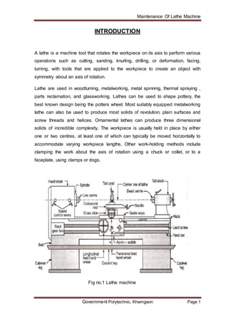
  • 1. Maintenance Of Lathe Machine Government Polytechnic, Khamgaon Page 1 INTRODUCTION A lathe is a machine tool that rotates the workpiece on its axis to perform various operations such as cutting, sanding, knurling, drilling, or deformation, facing, turning, with tools that are applied to the workpiece to create an object with symmetry about an axis of rotation. Lathe are used in woodturning, metalworking, metal spinning, thermal spraying , parts reclamation, and glassworking. Lathes can be used to shape pottery, the best known design being the potters wheel. Most suitably equipped metalworking lathe can also be used to produce most solids of revolution, plain surfaces and screw threads and helices. Ornamental lathes can produce three dimensional solids of incredible complexity. The workpiece is usually held in place by either one or two centres, at least one of which can typically be moved horizontally to accommodate varying workpiece lengths. Other work-holding methods include clamping the work about the axis of rotation using a chuck or collet, or to a faceplate, using clamps or dogs. Fig no.1 Lathe machine
  • 2. Maintenance Of Lathe Machine Government Polytechnic, Khamgaon Page 2 HISTORY Lathes were developed as early as the 15th century and were known as "bow" lathes. The operator rotated the workpiece by drawing a bow back and forth, either by hand or with the use of a foot treadle. Next came Bessons lathe in 1568, which was driven by a cord passing over a pulley above the machine. This in turn drove two other pulleys on the same shaft which rotated the workpiece and a crude, wooden lead screw, which in turn allowed the operator to remove metal from the piece being machined. The screw cutting lathe originates in the 17th century. Development and advancements have continued and today we have sophisticated computerized controlled lathes. Lathes have allowed man to reshape, machine and manufacture many precision cylindrical components made of various types of metal, wood, plastics, and other materials. Without the lathe, man would still be trying to produce cylindrical components in some crude fashion or another. However, because of advanced technology, the lathe has allowed man to become an important asset in developing and machining many precision components needed to operate and function in many areas of our industrial complex. Fig no 2. Olden Type of Lathe Machine
  • 3. Maintenance Of Lathe Machine Government Polytechnic, Khamgaon Page 3 TYPES OF LATHE 1) Engine Lathes These are probably the most popular among the lathe machines. In fact, no machine soft is seen without this type of lathe. The good thing about engine lathe is that it can be used in various materials, asides from metal. Moreover, the setup of these machines is so simple that they are easier to use. Its main components include the bed, headstock and tailstock. These engine lathes can be adjusted to variable speed for the accommodation of a wide scope of work. In addition, these lathe come in various sizes. 2) Turret Lathes These types of lathes are used for machining single workpieces sequentially. This means that several operations are needed to be performed on a single workpiece. With thw turret lathes, sequential operations can be done on the workpiece, eliminating errors in work alignment. With this setup, machining is done more efficiently. Correspondingly, time is saved because there is no need to remove and transfer the workpiece to another machine anymore. 3) Special Purpose Lathes As name implies, these lathes are used for special purpose such as heavy duty production of identical parts. In addition, these lathe also perform specific functions that cannot be performed by the standard lathes. Some examples of special purpose lathes include the bench type jeweler’s lathes, automatic lathes, crank shaft lathes, duplicating lathes, multispindle lathes, breakdrum lathes and production lathes among others.
  • 4. Maintenance Of Lathe Machine Government Polytechnic, Khamgaon Page 4 BASIC PARTS OF LATHE 1) Bed and Ways. The bed is the base for the working parts of the lathe. The main feature of the bed is the ways which are formed on the bed's upper surface and which run the full length of the lathe. The tailstock and carriage slide on the ways in alignment with the headstock. The headstock is normally permanently bolted at one end (at the operator's left). The ways are accurately machined parallel to the axis of the spindle and to each other. The V-ways are guides that allow the carriage and the tailstock to move over them only in their longitudinal direction. The flat way takes most of the downward thrust. The carriage slides on the outboard V-ways which, because they are parallel to the V-ways, keep the carriage in alignment with the headstock and tailstock at all times. This is an absolute necessity if accurate lathe work is to be done. Some lathe beds have two V-ways and two flat ways, while others have four V-ways. For satisfactory performance of a lathe, the ways must be kept in good condition. A common fault of careless machinists is to use the bed as an anvil for driving arbors or as a shelf for hammers, wrenches, and chucks. Never allow anything to strike the ways or damage their finished surfaces in any way. Keep them free of chips. Wipe them off daily with an oiled cloth to help preserve their polished surface. Fig no. 3 Bed and guide ways of Lathe machine
  • 5. Maintenance Of Lathe Machine Government Polytechnic, Khamgaon Page 5 2) Headstock The headstock carries the head spindle and the mechanism for driving it. In the belt-driven type headstock, the driving mechanism consists merely of a cone pulley that drives the spindle directly or through the back gears. When the spindle is driven directly, it rotates the cone pulley. When the spindle is driven through the back gears, it rotates more slowly than the cone pulley, which in this case turns freely on the spindle. Thus two speeds are available with each position of the belt on the cone; if the cone pulley has four steps, eight spindle speeds are available. The geared headstock shown in figure is more complicated but more convenient to operate, because the speed is changed by changing or by shifting the gears. This headstock is similar to an automobile transmission except that it has more gear-shift combinations and, therefore, has a greater number of speed changes. A speed index plate, attached to the headstock, indicates the lever positions for the different spindle speeds. To avoid damage to the gear teeth, the lathe is always stopped before the gears are shifted. Figure shows the interior of a typical geared headstock that has 16 different spindle speeds. The driving pulley at the left is driven at a constant speed by a motor located under the headstock. Various combinations of gears in the headstock transmit power from the drive shaft to the spindle through an intermediate shaft. Fig no. 4 Headstock
  • 6. Maintenance Of Lathe Machine Government Polytechnic, Khamgaon Page 6 3) Tailstock The primary purpose of the tailstock is to hold the dead center to support one end of the work being machined between centers. However, it can also be used to hold live centers, tapered shank drills, reamers, and drill chucks. The tailstock moves on the ways along the length of the bed to accommodate work of varying lengths. It can be clamped in the desired position by the tailstock clamping nut. The dead center is held in a tapered hole (bored to a Morse taper) in the tailstock spindle. The spindle is moved back and forth in the tailstock barrel for longitudinal adjustment. The handwheel is turned which turns the spindle-adjusting screw in a tapped hole in the spindle. The spindle is kept from revolving by a key that fits a spline, or keyway, cut along the bottom of the spindle. The tailstock body is made in two parts. The bottom, or base, is fitted to the ways; the top can move laterally on its base. The lateral movement can be closely adjusted by setscrews. Zero marks inscribed on the base and top indicate the center position and provide a way to measure set over for taper turning. Before inserting a dead center, a drill, or a reamer into the spindle, carefully clean the tapered shank and wipe out the tapered hole of the spindle. After a drill or reamer is placed into the tapered hole of the spindle, make sure that the tool will not turn or revolve. If the tool is allowed to revolve, it will score the tapered hole and destroy its accuracy. The spindle of the tailstock is engraved with graduations which help in determining the depth of a cut when a piece is drilled or reamed. Fig no. 5 Tailstock
  • 7. Maintenance Of Lathe Machine Government Polytechnic, Khamgaon Page 7 4) Carriage The carriage carries the crossfeed slide and the compound rest whichin turn carries the cutting tool in the toolpost. The carriage slides on the ways along the bed. The wings of the H-shaped saddle contain the bearing surfaces which are fitted to the Vways of the bed. The cross piece is machined to form a dovetail for the crossfeed slide. The crossfeed slide is closely fitted to the dovetail and has a tapered gib which fits between the carriage. dovetail and the matching dovetail of the cross feed slide. The gib permits small adjustments to remove any looseness between the two parts. The slide is securely bolted to the crossfeed nut which moves back and forth when the crossfeed screw is turned by the handle. The micrometer dial on the crossfeed handle is graduated to permit accurate feed. Depending on the manufacturer of the lathe, the dial may be graduated so that each division represents a 1 to 1 ratio. The compound rest is mounted on top of the crossfeed slide. The carriage has T-slots or tapped holes for clamping work for boring or milling operations. When the lathe is used in this manner, the carriage movement feeds the work to the cutting tool which is revolved by the headstock spindle. The carriage can be locked in any position on the bed by tightening the carriage clamp screw. The clamp screw is to be used only when doing work for which longitudinal feed is not required, such as facing or cutting off stock. Normally, the carriage clamp is kept in the released position. The carriage is always moved by hand to make sure that it is free before the automatic feed is applied. The carriage consists of the tool post which carries the tool used in lathe machine. Fig no. 6 Carriage
  • 8. Maintenance Of Lathe Machine Government Polytechnic, Khamgaon Page 8 5) Lead screw The lead screw is used for thread cutting. Along its length are accurately cut Acme threads which engage the threads of the half-nuts in the apron when the half-nuts are clamped over it. When the lead screw turns inside the closed half- nuts, the carriage moves along the ways a distance equal to the lead of the thread in each revolution of the lead screw. Since the lead screw is connected to the spindle through a gear train the lead screw rotates with the spindle. Whenever the half-nuts are engaged, the longitudinal movement of the carriage is directly controlled by the spindle rotation. The cutting tool is moved a definite distance along the work for each revolution of the spindle. The ratio of the threads per inch of the thread being cut and the thread of the lead screw is the same as the ratio of the speeds of the spindle and the lead screw. For example: If the lead screw and spindle turn at the same speed, the number of threads per inch being cut is the same as the number of threads per inch of the lead screw. If the spindle turns twice as fast as the lead screw, the number of threads being cut is twice the number of threads per inch of the lead screw. The ratio of the threads per inch of the thread being cut and the thread of the lead screw is the same as the ratio of the speeds of the spindle and the lead screw. For example: If the lead screw and spindle turn at the same speed, the number of threads per inch being cut is the same as the number of threads per inch of the lead screw. If the spindle turns twice as fast as the lead screw, the number of threads being cut is twice the number of threads per inch of the lead screw. Fig no 7 Lead screw
  • 9. Maintenance Of Lathe Machine Government Polytechnic, Khamgaon Page 9 6) Quick Change GearMechanism To do away with the inconvenience and loss of time involved in removing and replacing change gears, most modern lathes have a selfcontained change gear mechanism, commonly called a "quick-change gear box." There are a number of types used on different types of lathes, but they are all similar in principle. The quick-change gear box mechanism consists of a cone- shaped group of change gears. One can instantly connect any single gear in the gear train by a sliding tumbler gear controlled by a lever. The cone of gears is keyed to a shaft which drives the lead screw (or feed rod) directly or through an intermediate shaft. Each gear in the cluster has a different number of teeth and hence produces a different ratio when connected in the train. Sliding gears also produce other changes in the gear train to increase the number of different ratios one can get with the cone of change gears. All changes are made by shifting the appropriate levers or knobs. An index plate or chart mounted on the gear box indicates the position in which to place the levers to obtain the necessary gear ratio to cut the threads or produce the feed desired. Figure depicts the rear view of one type of gear box. The splined shaft turns with gear G, which is driven by the spindle through the main gear train mounted on the end of the lathe. Shaft F in turn drives shaft H through the tumbler gear T, which can be engaged with any one of the cluster of eight different size gears on shaft H by means of the lever C. Shaft H drives shaft J through a double-clutch gear, which takes the drive through one of three gears, depending on the position of lever B (right, center or left). Shaft J drives the lead screw through gear L. Either the lead screw or the feed rod can he connected to the final driveshaft of the gear box by engaging the appropriate gears. The lathe gear box shown in figure has no feed rod. Twenty- four different gear ratios are provided by the quick-change gear box. The lower lever has eight positions, each of which places a different gear in the gear train and hence produces eight different gear ratios. The three positions of the upper level produce three different gear ratios for each of the 8 changes obtained with the lower lever, thus making 24 combinations in the box alone. This range can be doubled by using the sliding compound gear which provides a high- and low-gear ratio in the main gear train. This gives two ratios for every combination obtainable in the box, 48 combinations in all.
  • 10. Maintenance Of Lathe Machine Government Polytechnic, Khamgaon Page 10 LATHE ACCESSORIES The lathe machines are provided with different accessories. Lathe accessories are used for holding and supporting the work and holding the tool. The following are the accessories employed with the lathe. 1) Centre The lathe centres are used for supporting the work during turning operations. There are two centres i.e. live centre and dead centre. The workpiece is held between these two centres. 2) Chuck A chuck is one of the most important devices for holding and rotating the piece of the work on lathe. It is attached to the headstock spindle by the means of bolts with back plates and set scews on the spindle nose. Types of chucks:  Three jaw chuck.  Four jaw chuck.  Combination chuck.  Collect chuck.  Spindle chuck.  Magnetic chuck.  Air operated chuck. 3) Face plates It is a cast iron circular disc, having a threaded hole a its centre so that it can be screwed on the threaded nose of the spindle. There are number of holes and slots provided on this plate. It is used for holding the work, which cannot be held between centres or on the chuck. The work is held with the help of clamping plates and bolts.
  • 11. Maintenance Of Lathe Machine Government Polytechnic, Khamgaon Page 11 4) Driving plate or catch plate A catch plate is plane disc made up of cast iron or steel. It has a central boss and catch pin projecting from it. It is screwed on the threaded nose of headstock spindle. It is used for driving the work with the help of projecting pin on it, with the dog or carries clamp to work while turning the work between the centres. 5) Angle plate Angle plate is a “L” shaped cast iron plate. Two faces of the plates are at right angle and having slots for clamping face plate on its surface. It is used for holding the work, which is not possible to mount directly on the face plate. 6) Mandrel Mandrel is a device used for holding a hollow workpiece that has been previously drilled or bored. It is the solid shaft made up of high carbon steel. It is mounted between centres and work revolves with it. It is driven by the driving plate and carrier. Different types of mandrel are:  Plain mandrel.  Collar mandrel.  Cone mandrel.  Expansion mandrel.  Step mandrel. 7) Rest It is the device which is used to support long slender jobs at an intermediate point to prevent it from bending, due to its own weight and vibration caused by cutting force acting on it. Rest will be used when length of workpiece is more than 12 times its diameter. Common types of rest used are:  Steady rest.  Follower rest.
  • 12. Maintenance Of Lathe Machine Government Polytechnic, Khamgaon Page 12 OPERATIONS PERFORMED ON LATHE MACHINE 1) Facing Facing is the square finishing of the ends of the workpiece and is often used to bring the piece to a specified length. In facing operations, the cutter bit does not traverse laterally (left or right) but cuts inward or outward from the axis of the piece. Facing of the ends is usually performed before turning operations. 2) Straight turning Straight turning may he performed upon a workpiece supported in a chuck, but the majority of workpieces turned on an engine lathe are turned between centers. Turning is the removal of metal from the external surface of cylindrical workpieces using various types of cutter toolbits. 3) Finish turning When the workpiece has been rough turned to within about 1/32 inch of the finished size, take a finishing cut. A fine feed, the proper lubricant, and above all a keen-edged toolbit are necessary to produce a smooth finish. Measure carefully to be sure that the workpiece is being machined to the proper dimension. The lathe should be stopped whenever measurements are to be made. 4) Parting One of the methods of cutting off a piece of stock while it is held in a lathe is a process called parting. This process uses a specially shaped tool with a cutting edge similar to that of a square nose cutting tool. The parting tool is fed into the rotating workpiece, perpendicular to its axis, cutting a progressively deeper groove as the workpiece rotates. When the cutting edge of the tool gets to the center of the workpiece being parted, the workpiece drops off. Parting is used to cut off parts that have already been machined in the lathe, or to cut tubing and bar stock to their required lengths.
  • 13. Maintenance Of Lathe Machine Government Polytechnic, Khamgaon Page 13 5) Taper turning In ordinary straight turning, the cutting tool moves along a line parallel to the axis of the work, causing the finished job to be the same diameter throughout. However, when cutting a taper, the tool moves at an angle to the axis of the work, producing a taper. Therefore, to turn a taper, the work must either be mounted in a lathe so that the axis upon which it turns is at an angle to the axis of the lathe, or cause the cutting tool to move at an angle to the axis of the lathe. 6) Chamfering Chamfering is operation of producing a bevel shape finish at the end of workpiece. Chamfering is done for removing burrs and for protecting the end from getting damaged. Chamfering is essential after thread cutting operation. It may be performed after turning, knurling, boring, drilling etc. 7) Knurling Knurling is the operation of producing a diomand shaped pattern on the surface of the workpiece. The purpose of knurling is to provide an effective gripping surface on a workpiece to prevent it from slipping when operated by hand. Knurling is provided on handle of the machine and gauges. It is done by the knurling tool, which consists of hardened steel rollers in a holder. The rollers have a teeth cut in a definite pattern on their surface. Knurling is done at very low speed. The feed during knurling varies from 1mm to 2 mm per revolution. 8) Drilling Drilling is the operation of producing a cylindrical hole by removing metal by the rotating edge of the cutting tool called as drill. The workpiece is held in chuck and drill tool is fitted in tailstock barrel. The drill is fed to workpiece by rotating hand wheel of tailstock. The speed of feed during drilling is 25% less than normal speed.
  • 14. Maintenance Of Lathe Machine Government Polytechnic, Khamgaon Page 14 CUTTING TOOL USED IN LATHE MACHINE The main function of the cutting tool is to remove the unwanted material from the work piece in form of chips to give it desire shape and size. In metal cutting process chip can be removed either by cutting having cutting edges or by abrasive i.e. gringing wheel. The cutting tools can be classified as: 1) On the basis of cutting edges.  Single point cutting tool.  Multi-point cutting tool. 2) On the basis of motion of tool.  Linear motion tool.  Rotary motion tool.  Linear and rotary motion tool. Single point cutting tool (1) Shank:- The shank is the main body of the tool. (2) Nose:- The nose is the part of the cutter bit which is shaped to produce the cutting edges. (3) Face :- The face of the cutter bit is the surface at the upper side of the cutting edge on which the chip strikes as it is separated from the workpiece. (4) Side :- The side of the cutter bit is the near-vertical surface which, with the end of the bit, forms the profile of the bit. The side is the leading surface of the cutter bit used when cutting stock. (5) Base :- The base is the bottom surface of the shank of the cutter bit.
  • 15. Maintenance Of Lathe Machine Government Polytechnic, Khamgaon Page 15 (6) End :- The end of the cutter bit is the near-vertical surface which, with the side of the bit, forms the profile of the bit. The end is the trailing surface of the cutter bit when cutting. (7) Heel :- The heel is the portion of the cutter bit base immediately below and supporting the face. Fig no 8 Single point cutting tool.
  • 16. Maintenance Of Lathe Machine Government Polytechnic, Khamgaon Page 16 SIZE AND SPECIFICATION OF LATHE MACHINE 1) Size Of Lathe Machine  The height of the centre over the bed.  The length between the centres : It is the maximum length of the workpiece that can be held in between the lathe centres.  The swing diameter over the bed : It is the maximum length diameter of the workpiece that can be revolving without touching the bed. It is twice the height of the centres.  The swing diameter over the carriage : It is the maximum diameter of the workpiece that can swing over the carriage. It is always less than the swing diameter over bed.  The maximum bar diameter : It is the maximum diameter of the bar stock that will pass through the hollow headstock spindle.  Length of the bed. 2) SpecificationOf Lathe Machine  Floor space occupied:- ( 175 x 45 x 115 ) cm  Bed:- ( 115 x 25 ) cm  Carriage:- ( 35 x 30 ) cm  Speed ( chuck) :- 224 – 1200 rpm  Motor used :- 1.5 HP  Maximum bar diameter:- 60mm
  • 17. Maintenance Of Lathe Machine Government Polytechnic, Khamgaon Page 17 TOOLKIT 1) Hex key : A hex key or allen key of hexagonal cross section used to drive the bolts and the screws that have a hexagonal socket in the head. 2) Open End Wrench : It is solid nonadjustable wrenches with opening either on one or both ends called open-end wrenches. 3) Spanner : Spanner is the tool used to provide grip and mechanical advantage in applying torque to turn the object.
  • 18. Maintenance Of Lathe Machine Government Polytechnic, Khamgaon Page 18 4) Screw Driver : A screw driver is one of the most basic operating hand tool. It is most frequently used hand too of all. 5) Hammer : Hammers are mostly used by the people who work with metal or around the machinery. Hammer mostly used for press fitting or making sheets. 6) Box Wrenches : Box wrenches are safer than opened end wrenches. 7) Plier : Pliers are the hand tool used to hold the object firmly, possibly developed from tongs.
  • 19. Maintenance Of Lathe Machine Government Polytechnic, Khamgaon Page 19 TROUBLE SHOOTINGS Problem Checklist/Remedy 1) There was no free movement of the carriage, tool-post. We clean the guide ways, and oiled it properly for the free movement. 2) The internal gearing of the lathe machine was damaged. We replaced the gears to run the machine properly. 3) The tailstock of the lathe machine had no movement. We maintained the tailstock with proper lubrication to function properly. 4) The coolant system of the lathe machine was damaged completely. We replaced the motor of the coolant system, removed the rust inside the tank. 5) The lathe machine had the stopper problem. The alignment of the stopper was disturbed. We aligned the stopper properly to work well. Table no 1 Trouble shooting
  • 20. Maintenance Of Lathe Machine Government Polytechnic, Khamgaon Page 20 MAINTENANCE CHART Maintenance chart for lathe machine for three months Sr.no Name of month Maintenance done 1. January 1) Clean the entire machine. 2) Made the parts of the machine to work smoothly. 3) Replaced the internal gears. 2. February 1) Stopper problem of the machine. 2) Coolant system 3. March 1) Lubrication to parts of machine. 2) Final touch to the machine. Table no 2 Maintenance Chart
  • 21. Maintenance Of Lathe Machine Government Polytechnic, Khamgaon Page 21 SAFETY 1) In machining operations, there is one sequence of events that one must always follow: safety first, accuracy second, and speed last. With this in mind, let's look at some of the more important safety precautions that should be observed before and during lathe operations. 2) Lathe accidents are usually caused by:  Loose clothing snagging on the revolving workpiece, the chuck, or the work piece.  Flying chips entering the eye when turning cast iron or nonferrous metals.  Contact of the hands or arms with the lathe dog, chuck or workpiece. 3) The operator should prepare himself by rolling up his shirt sleeves and removing watches, rings, and other jewelry that might become caught while he is operating the machine. 4) The operator should be sure to wear safety glasses or a face shield of the approved type at all times when operating a lathe or when in the area of lathes that are in operation. 5) The operator should be sure that the work area is clear of obstructions that one might fall over or trip on. 6) On turret lathes, care must be taken not to catch loose or torn clothing on a stock that is supported in the collet with chucks and extends beyond the headstock of the lathe. 7) If a coolant or cutting oil is used, the operator should take care when adjusting the splash pans to prevent the liquid from splashing on the floor. The cutting oil or coolant can make the floor beneath the lathe slippery and cause the operator to lose his balance and suffer injury. 8) The operator will keep the floor around the machine clear of oil or grease to prevent anyone from slipping and falling into the machine. 9) The operator should use assistance when handling heavy or awkward parts, stock, or machine accessories. Never remove chips with your bare hands.
  • 22. Maintenance Of Lathe Machine Government Polytechnic, Khamgaon Page 22 COST ESTIMATION MATERIALS QUANTITY COST (Rs) Gears 3 nos 7500 Machine oil 3000ml 330 Kerosene 2000 ml 80 Oil Paint 200 ml 90 Motor 1 nos 150 Wire, Plug 7 feets 90 Other Cost - 100 Total 8340 Table no. 3 Cost Estimation
  • 23. Maintenance Of Lathe Machine Government Polytechnic, Khamgaon Page 23 CONCLUSION :- In this project we have studied about Lathe machine and get knowledge about all parts of the machine. We had repaired the machine and remove the faulty parts from it and did the maintenance chart. While doing this maintenance we face many difficulties and their remedies. We get the knowledge about the various parts of the Lathe machine. We expect that our maintenance will helpful for the workshop department in future period. In this way we maintained the lathe machine.
  • 24. Maintenance Of Lathe Machine Government Polytechnic, Khamgaon Page 24 REFERENCES  Maintenance engineering and management .Author :- Sushil Kumar Srivastava  Lathe machine manual. Author: - CMT COMEX.  SJ 2060 Manual Lathe.  Lathe operations and maintenance. Author: - John G. Edwards  Manufacturing processes. :- nirali prakashan  http:/en.m.wikipedia.org/wiki/lathe.(machine)  http:/m.wikihow.com/set-up-a-lathe-machine  http:/www.thomasnet.com/about/lathe-machine-51276103.html  http:/www.sciencedirect.com
  • 25. Maintenance Of Lathe Machine Government Polytechnic, Khamgaon Page 25 SNAPSHOTS 1) Machine before maintenance. 2) Machine under maintenance.
  • 26. Maintenance Of Lathe Machine Government Polytechnic, Khamgaon Page 26 3) Maintenance of gears.
  • 27. Maintenance Of Lathe Machine Government Polytechnic, Khamgaon Page 27 4) Maintenance of carriage. 5) Maintenance of tailstock.
  • 28. Maintenance Of Lathe Machine Government Polytechnic, Khamgaon Page 28 6) Maintenance of coolant tank.
  • 29. Maintenance Of Lathe Machine Government Polytechnic, Khamgaon Page 29 7) Machine after maintenance