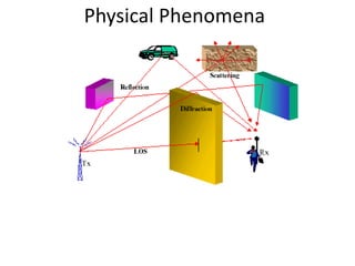
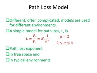
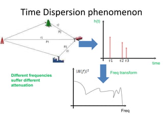
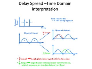
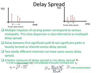
The document summarizes key concepts related to wireless fading channels, including:
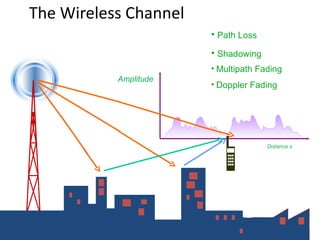
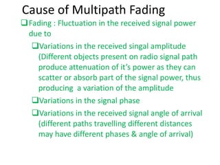
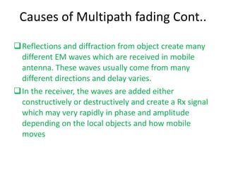
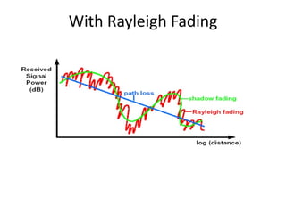
1. Multipath fading causes fluctuations in signal strength over small physical distances due to constructive and destructive interference from multiple signal paths.
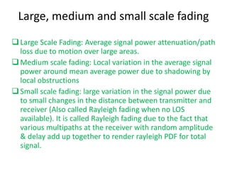
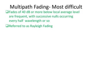
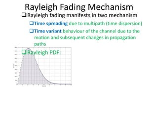
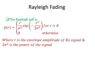
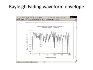
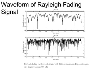
2. Rayleigh fading occurs when there is no line-of-sight path between transmitter and receiver, resulting in fast, large fluctuations in signal strength over small physical distances.
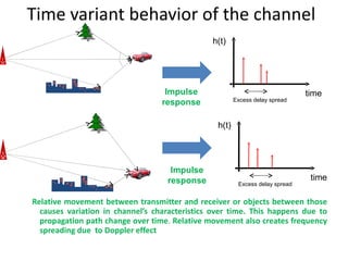
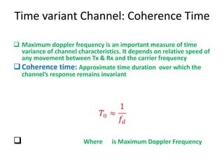
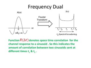
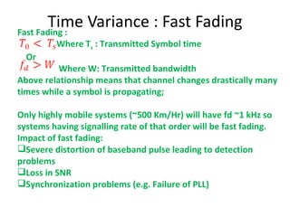
3. Doppler spread and coherence time describe how quickly the wireless channel varies over time due to mobility, with fast fading occurring if the channel changes significantly within a symbol period.