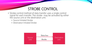
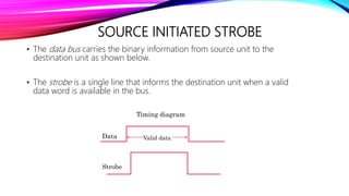
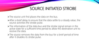
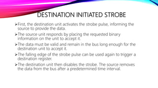
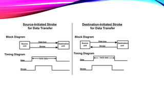
COMPUTER ORGANIZATION &
ARCHITECTURE
Name : Mitali Maniyar
En.No.:150410107048
Class : SY CE-1
Dept. : Computer
ASYNCHRONOUS DATA TRANSFER
• In a computer system, CPU and an I/O interface are designed
independently of each other.
• When internal timing in each unit is independent from the other
and when registers in interface and registers of CPU uses its own
private clock.
• In that case the two units are said to be asynchronous to each
other. CPU and I/O device must coordinate for data transfers.
2
• In asynchronous the transmission of data is generally without the use of an
external clock signal, where data can be transmitted intermittently rather than in a
steady stream.
• The most significant aspect of asynchronous communications is that data is not
transmitted at regular intervals, thus making possible variable bit rate.
• And that the transmitter and receiver clock generators do not have to be exactly
synchronized all the time.
• Hence we need a start and stop signal to send and receive data.
METHODS USED IN
ASYNCHRONOUS DATA TRANSFER
• Strobe Control: This is one way of transfer i.e. by means of strobe pulse
supplied by one of the units to indicate to the other unit when the
transfer has to occur.
• Handshaking: This method is used to accompany each data item being
transferred with a control signal that indicates the presence of data in
the bus. The unit receiving the data item responds with another control
signal to acknowledge receipt of the data.
4
STROBE CONTROL
• Strobe control method of data transfer uses a single control
signal for each transfer. The strobe may be activated by either
the source unit or the destination unit.
• Source Initiated Strobe
• Destination Initiated Strobe
5
Source
Unit
Destination
Unit
Data bus
Strobe
SOURCE INITIATED STROBE
• The data bus carries the binary information from source unit to the
destination unit as shown below.
• The strobe is a single line that informs the destination unit when a valid
data word is available in the bus.
Valid dataData
Strobe
Timing diagram
SOURCE INITIATED STROBE
The source unit first places the data on the bus.
After a brief delay to ensure that the data settle to a steady value, the
source activities the strobe pulse.
The information of the data bus and the strobe signal remain in the
active state for a sufficient time period to allow the destination unit to
receive the data.
The source removes the data from the bus for a brief period of time
after it disables its strobe pulse.
DESTINATION INITIATED STROBE
First, the destination unit activates the strobe pulse, informing the
source to provide the data.
The source unit responds by placing the requested binary
information on the unit to accept it.
The data must be valid and remain in the bus long enough for the
destination unit to accept it.
The falling edge of the strobe pulse can be used again to trigger a
destination register.
The destination unit then disables the strobe. The source removes
the data from the bus after a predetermined time interval.
Source
unit
Destination
unit
Data bus
Strobe
Data
Strobe
Valid data
Source-Initiated Strobe
for Data Transfer
Source
unit
Destination
unit
Data bus
Strobe
Data
Strobe
Valid data
Block Diagram
Destination-Initiated Strobe
for Data Transfer
Timing Diagram
Block Diagram
Timing Diagram
COA asynchronous data transfer

COA asynchronous data transfer

  • 1.
    COMPUTER ORGANIZATION & ARCHITECTURE Name: Mitali Maniyar En.No.:150410107048 Class : SY CE-1 Dept. : Computer
  • 2.
    ASYNCHRONOUS DATA TRANSFER •In a computer system, CPU and an I/O interface are designed independently of each other. • When internal timing in each unit is independent from the other and when registers in interface and registers of CPU uses its own private clock. • In that case the two units are said to be asynchronous to each other. CPU and I/O device must coordinate for data transfers. 2
  • 3.
    • In asynchronousthe transmission of data is generally without the use of an external clock signal, where data can be transmitted intermittently rather than in a steady stream. • The most significant aspect of asynchronous communications is that data is not transmitted at regular intervals, thus making possible variable bit rate. • And that the transmitter and receiver clock generators do not have to be exactly synchronized all the time. • Hence we need a start and stop signal to send and receive data.
  • 4.
    METHODS USED IN ASYNCHRONOUSDATA TRANSFER • Strobe Control: This is one way of transfer i.e. by means of strobe pulse supplied by one of the units to indicate to the other unit when the transfer has to occur. • Handshaking: This method is used to accompany each data item being transferred with a control signal that indicates the presence of data in the bus. The unit receiving the data item responds with another control signal to acknowledge receipt of the data. 4
  • 5.
    STROBE CONTROL • Strobecontrol method of data transfer uses a single control signal for each transfer. The strobe may be activated by either the source unit or the destination unit. • Source Initiated Strobe • Destination Initiated Strobe 5 Source Unit Destination Unit Data bus Strobe
  • 6.
    SOURCE INITIATED STROBE •The data bus carries the binary information from source unit to the destination unit as shown below. • The strobe is a single line that informs the destination unit when a valid data word is available in the bus. Valid dataData Strobe Timing diagram
  • 7.
    SOURCE INITIATED STROBE Thesource unit first places the data on the bus. After a brief delay to ensure that the data settle to a steady value, the source activities the strobe pulse. The information of the data bus and the strobe signal remain in the active state for a sufficient time period to allow the destination unit to receive the data. The source removes the data from the bus for a brief period of time after it disables its strobe pulse.
  • 8.
    DESTINATION INITIATED STROBE First,the destination unit activates the strobe pulse, informing the source to provide the data. The source unit responds by placing the requested binary information on the unit to accept it. The data must be valid and remain in the bus long enough for the destination unit to accept it. The falling edge of the strobe pulse can be used again to trigger a destination register. The destination unit then disables the strobe. The source removes the data from the bus after a predetermined time interval.
  • 9.
    Source unit Destination unit Data bus Strobe Data Strobe Valid data Source-InitiatedStrobe for Data Transfer Source unit Destination unit Data bus Strobe Data Strobe Valid data Block Diagram Destination-Initiated Strobe for Data Transfer Timing Diagram Block Diagram Timing Diagram