SlideShare a Scribd company logo
1 of 26
Download to read offline
cm-eibFOR LOGO!
Communication with LOGO!
with EIB and the Konnex standard
Manual Release 09/2002
s
CM EIB/KNX
LOGO! Expansion Module
Manual
Chapters
Safety Notices
1 Getting to know CM EIB
2 Mounting and wiring the CM EIB
3 Putting the CM EIB into operation
4 Supported functions
5 CM EIB specifications
INDEX
CM EIB/KNX
CM EIB
2 J31069-D1262-U002-A4-7618
Copyright - Siemens AG 1996 to 2002 All rights reserved
You may not transfer or duplicate this document or utilize or reveal its contents,
unless expressly authorized in writing. In the case of a violation, you will be obliged
to pay damages. All rights reserved, in particular in the event that a patent is
granted or that a utility model is registered.
Disclaimer of liability:
We have checked that the contents of this document correctly describe the
associated hardware and software. Nonetheless, it is impossible to exclude the
possibility of deviations and therefore we cannot guarantee that there are no errors
in this document. The information in this document is checked regularly and any
necessary corrections are then made in the next release issued. We are of course
thankful for any suggestions for improvements.
CM EIB/KNX
CM EIB
J31069-D1262-U002-A4-7618 3
Table of Contents
Safety Notices
1 Getting to know CM EIB...................................... 5
1.1 What is the CM EIB? ............................................. 5
1.2 The construction of the CM EIB............................. 6
2 Mounting and wiring the CM EIB/KNX............... 7
2.1 General guidelines ................................................. 7
2.2 Wiring the CM EIB ................................................. 9
2.2.1 Connecting the power supply 10
2.2.2 Connecting the EIB 11
3 Putting the CM EIB into operation ................... 12
3.1 Step-by-step......................................................... 12
3.2 The CM EIB - operational status.......................... 13
3.3 Behavior in case of a fault.................................... 15
4 Supported functions.......................................... 16
4.1 Inputs / Outputs.................................................... 16
4.2 Available communication objects......................... 18
4.3 EIB configuration.................................................. 19
5 CM EIB - Specifications..................................... 22
CM EIB/KNX
CM EIB
4 J31069-D1262-U002-A4-7618
Indicates that death or severe
bodily injury may occur, if the
corresponding safety measures
are not taken.
Safety Notices
DANGER
WARNING
CAUTION
CAUTION
WARNING
Indicates that death, severe bodily
injury or substantial material damage
will occur, if the corresponding safety
measures are not taken.
With the warning triangle, this
indicates that minor bodily
injury may occur, if the
corresponding safety measures
are not taken.
Without the warning triangle,
this indicates that material
damage may occur, if the
corresponding safety measures
are not taken.
This indicates that an undesirable
result or condition may occur, if the
corresponding instructions are not
observed.
CM EIB/KNX
CM EIB
J31069-D1262-U002-A4-7618 5
1 Getting to know CM EIB
1.1 What is the CM EIB?
This is the communications module (CM) for connecting the
LOGO! to the EIB bus.
The LOGO! communications module has been implemented
as a Slave module for the LOGO control module (12/24 or
115/240 Volt).
The module supports communication between the LOGO!
Master and external EIB devices via an EIB.
The CM is a bus participant on the EIB and allows the LOGO!
to communicate with other EIB devices using EIB telegrams.
What are the capabilities of the CM EIB?
The CM transfers EIB telegrams to the LOGO! and LOGO!
functions to the EIB.
The CM presents the current states of the EIB devices to the
LOGO!, which is thus able to use its logical functions und
timers to join them together. In the process, the EIB signals
can also be combined with the signals of the local LOGO!
inputs and outputs. The CM then transmits every change of
the output signal via the EIB.
The combination of LOGO! and CM EIB gives the user a
decentralized controller functionality for the EIB with the
capability of setting or changing parameters or operations
quickly, simply and without a programming device.
CM EIB/KNX
CM EIB
6 J31069-D1262-U002-A4-7618
1.2 The construction of the CM EIB
1. Power supply
2. Bus lock slide, interface to the LOGO!
3. The RUN/STOP LED for communication with LOGO!
4. The BUS LED, EIB communications
5. Label for the physical address
6. Inputs - EIB connection
7. Expansion interface to the LOGO!
8. Mechanical coding - pin
9. Programming button
CM EIB/KNX
CM EIB
J31069-D1262-U002-A4-7618 7
2 Mounting and wiring the CM EIB/KNX
2.1 General guidelines
• The following guidelines must be observed when
mounting and wiring your CM EIB:
• When wiring the CM EIB, make certain that you follow all
of the applicable and legally binding standards. Observe
all of the relevant national and regional regulations when
installing and operating the device. Check with the local
authorities regarding the standards and regulations that
must be observed in your special case.
• Make certain that the device is de-energized.
• Use only approved bus cables.
• The EIB bus cables may also be laid parallel to other
lines.
• The CM EIB must always be installed as the last module
on the right of the LOGO!, since you may not install other
expansion modules onto the CM EIB.
CM EIB/KNX
CM EIB
8 J31069-D1262-U002-A4-7618
Please note:
- The CM EIB must have its own voltage supply (24V).
NOTE
This module may only be mounted and wired by qualified
personnel, who know and observe the generally applicable
guidelines and applicable regulations and standards.
Observe the assembly and disassembly instructions in the
LOGO! manual.
WARNING
The expansion module may only inserted or removed when
the power is off.
CM EIB/KNX
CM EIB
J31069-D1262-U002-A4-7618 9
2.2 Wiring the CM EIB
To wire the CM EIB, use a screwdriver with a 3 mm wide
blade.
There is no difference between the terminals of the LOGO!
and the EIB.
NOTE
To protect personnel against unintentional contact with the
portions of the CM EIB that are conducting electricity, the
appropriate national and local standards must be observed.
The CM EIB is a double-insulated switching device.
A protective grounding conductor is not necessary.
CM EIB/KNX
CM EIB
10 J31069-D1262-U002-A4-7618
2.2.1 Connecting the power supply
The CM EIB has been designed to serve as a Slave module
for the LOGO! controller. It must be connected to a
24 V AC/DC supply voltage.
Please observe the relevant instructions that are found in
product information that was included with your equipment as
well as the technical data regarding the permissible voltage
tolerances, mains frequency and current consumption.
Connecting
How to connect the CM EIB to the power:
CM EIB ..... with CM EIB ..... with
DC supply AC supply
Protect with a
80 mA/slow action fuse, if desired (recommended).
CM EIB/KNX
CM EIB
J31069-D1262-U002-A4-7618 11
2.2.2 Connecting the EIB
This connection is made using the two screw terminals (+
and -).
+ - EIB
X 2
3 4
RUN/STOP
BUS
6BK1700-0BA00-0AA0
Prog.Prog.
red black
Only the red – black pair is used,
the white – yellow pair is not connected.
You can set the CM EIB in the programming mode by
pressing on the “Prog ↓” button.
NOTE
Don't apply too much force when pressing the “Prog ↓”
button.
When contact has been made, the LED will light up in
orange.
CM EIB/KNX
CM EIB
12 J31069-D1262-U002-A4-7618
3 Putting the CM EIB into operation
3.1 Step-by-step
1. Both the BUS and supply voltage must be present.
2. Connect a PC to the serial EIB interface.
3. Start ETS. Use ETS2 Version 1.2.
4. Use ETS2, V.1.2 to configure the application program.
5. The application program is loaded into the devices via the
EIB interface. The application program is available for
downloading from the LOGO! homepage
(http://www.siemens.de/logo).
6. In ETS, click on “Program Physical Address”.
7. Press the button on the CM EIB to set the CM EIB in
programming mode; the LED will light up in orange.
8. When the LED goes out, the physical address has been
programmed. You can now note the physical address on
the device.
The syntax of the physical address:
Area / Line / Device
XX / XX / XXX
CM EIB/KNX
CM EIB
J31069-D1262-U002-A4-7618 13
9. The application program can now be loaded. Afterwards,
the device is ready for operation.
+ - EIB
X 2
3 4
RUN/STOP
BUS
6BK1700-0BA00-0AA0
Prog.Prog.
red black
10. If multiple CM EIBs have been installed in an EIB system,
repeat Steps 1 to 9 for each CM EIB.
11. For further details regarding the EIB installation, please
read the corresponding documentation.
3.2 The CM EIB - operational status
The CM EIB is a LOGO! expansion module.
This module has two LED displays:
1. “RUN/STOP” LED Communication with the LOGO!
2. “BUS” LED EIB-Bus status
CM EIB/KNX
CM EIB
14 J31069-D1262-U002-A4-7618
The “RUN/STOP” LED will light in green, red or orange.
LED Lights In
Green (RUN) Red (STOP) Orange
The expansion module
is communicating with
the device on the left.
The expansion module
is not communicating
with the device on the
left.
The expansion
module's initialization
phase
The “BUS” LED will light in green, red or orange.
LED Lights In
Green Red Orange
Bus connection OK,
communication OK,
not programming
mode
Bus connection fault Programming mode
active and bus
connection OK
CM EIB / KNX
RUN/STOP
BUS
+ - EIB
6BK1700-0BA00-0AA0
X 2
3 4
L+ M
Prog.
AC/DC 24V
CM EIB/KNX
CM EIB
J31069-D1262-U002-A4-7618 15
3.3 Behavior in case of a fault
LOGO! - Power failure
If the power to the LOGO! fails or the communications with
the LOGO! Master or the communications partner to the left
is interrupted, the outputs will be set to 0. The “RUN/STOP”
LED will light in RED after one second.
LOGO! - Power returns
The LOGO! will startup and the CM will send the
parameterized status.
CM - Power failure
All of the inputs of the EIB's LOGO! Master will be set by the
LOGO! Master to 0.
CM - Power returns
All of the LOGO!Master outputs on the EIB will be updated.
The inputs will be – depending on the EIB parameters – read.
BUS - Short-circuit or interruption
The inputs and outputs will retain their last value until they
receive a new one. After 5 seconds, the Bus LED will light in
red.
BUS - Restored
When the BUS is restored, the CM remains neutral, i.e. it
does not send any telegrams.
CM EIB/KNX
CM EIB
16 J31069-D1262-U002-A4-7618
4 Supported functions
The CM EIB supports the communications between the
LOGO! and EIB and supplies the I/O necessary for the
communication via the EIB.
4.1 Inputs / Outputs
The standard CM EIB application fills the complete LOGO!
process image.
I9 I10 I11 I12
Q1 Q2 Q3 Q4 Q5 Q6 Q7 Q8 A 1 A2
A3 ... A8
I13 ... I24 Sensorik
Q9 ... Q16 Aktorik
230 RC DM8 AM2 CM EIB/KNX
LOGO! 12/24 RC CM-EIB/KNX
I1 I2 I3 I4 I5 I6 I7 I8
A1 A2
A3 ... A8
I9 ... I24
Q5 ... Q16
Sensorik
Aktorik
EIB (Instabus)
EIB (Instabus)
I1 I2 I3 I4 I5 I6 I7 I8
Q1 Q2 Q3 Q4
CM EIB/KNX
CM EIB
J31069-D1262-U002-A4-7618 17
Sample application:
I1
I9 Q9
I14
Q16
Q6
Q1 I13
Q1 Q2 Q3 Q4 Q5 Q6 Q7 Q8
I1 I2 I3 I4 I5 I6 I7 I8 I9I10I11I12
1
2
3
I13 ... I24
Q9 ... Q16
EIB (Instabus)
&
DM 8 CM EIB/KNXLOGO!
1. To map the LOGO! inputs (I1 to I8and I9 to I12) as
outputs on the EIB, these must be joined with free EIB
outputs (Q9 to Q16) in the LOGO! application.
2. Operations (basic functions BF / special functions SF)
useable within the LOGO! application (e.g. as a feedback
signal).
3. To access the LOGO! application (Q1 to Q4 and Q5 to
Q8) directly via the bus communications, these must be
joined with free EIB inputs (I13 to I24) in the LOGO!
application.
CM EIB/KNX
CM EIB
18 J31069-D1262-U002-A4-7618
4.2 Available communication objects
An example of the basic variant – LOGO! CPU and CM EIB
without an expansion module:
The following communication objects will be available on the
EIB / KNX Bus:
EIB-Object No. Type (Size) EIS IN / OUT
0 UINT1 EIS1 I9 Input
1 UINT1 EIS1 I10 Input
2 UINT1 EIS1 I11 Input
3 UINT1 EIS1 I12 Input
4 UINT1 EIS1 I13 Input
5 UINT1 EIS1 I14 Input
6 UINT1 EIS1 I15 Input
7 UINT1 EIS1 I16 Input
8 UINT1 EIS1 I17 Input
9 UINT1 EIS1 I18 Input
10 UINT1 EIS1 I19 Input
11 UINT1 EIS1 I20 Input
12 UINT1 EIS1 I21 Input
13 UINT1 EIS1 I22 Input
14 UINT1 EIS1 I23 Input
15 UINT1 EIS1 I24 Input
16 UINT1 EIS1 Q5 Output
17 UINT1 EIS1 Q6 Output
18 UNIT1 EIS1 Q7 Output
19 UINT1 EIS1 Q8 Output
20 UINT1 EIS1 Q9 Output
21 UINT1 EIS1 Q10 Output
22 UINT1 EIS1 Q11 Output
23 UINT1 EIS1 Q12 Output
24 UINT1 EIS1 Q13 Output
25 UINT1 EIS1 Q14 Output
26 UINT1 EIS1 Q15 Output
27 UINT1 EIS1 Q16 Output
28 UINT16 / UINT8 EIS5 / EIS6 AI1 Input
29 UINT16 / UINT8 EIS5 / EIS6 AI2 Input
30 UINT16 / UINT8 EIS5 / EIS6 AI3 Input
31 UINT16 / UINT8 EIS5 / EIS6 AI4 Input
32 UINT16 / UINT8 EIS5 / EIS6 AI5 Input
33 UINT16 / UINT8 EIS5 / EIS6 AI6 Input
34 UINT16 / UINT8 EIS5 / EIS6 AI7 Input
35 UINT16 / UINT8 EIS5 / EIS6 AI8 Input
EIS1 (switches) 1 Bit
EIS 5 (EIB floating) 2 byte value
EIS 6 (EIB floating) 1 byte value
CM EIB/KNX
CM EIB
J31069-D1262-U002-A4-7618 19
4.3 EIB configuration
The following application parameters can be set in ETS2,
V.1.2:
- The number of digital I/Os on the LOGO! Master or
expansion modules
- The number of analog inputs on the LOGO! Master or
expansion modules
- The data type for each analog input EIS6 (scaling/8-bit
with sign) or EIS5 (EIB-Value Temp/8-bit without sign).
In the parameter dialog, you can set the number of inputs
and outputs that are already on the LOGO! (including
expansion modules) and how many are available via the EIB.
CM EIB/KNX
CM EIB
20 J31069-D1262-U002-A4-7618
The EIS5 values are converted to a fixed point numerical
value with a resolution of 0.1, which equates to a value range
of –3276.8 (FFFFh) to +3276.7 (7FFFh).
EIS6 values for scaling are accepted, i.e. 0 to 100 %
corresponds to an analog value of 0 to 255.
Unused analog inputs must be set to “Not Used”.
CM EIB/KNX
CM EIB
J31069-D1262-U002-A4-7618 21
Inputs/Outputs – Special Considerations
When using the LOGO! I/O on the CM EIB, you must
consider the following.
To access the LOGO! outputs (Q1 to Q4) directly via
communication over the bus, these must be joined in the
LOGO! application with free EIB inputs.
To map the LOGO! inputs (I1 to I8) as outputs on the bus,
these must be joined in the LOGO! application with free EIB
outputs.
The outputs on additional I/O modules can also be
transferred in parallel via the EIB.
CM EIB/KNX
CM EIB
22 J31069-D1262-U002-A4-7618
5 CM EIB - Specifications
Electrical Data
Supply voltage 24 V AC 24 V DC
Permissible range -15% +10% -15% +20%
Current consumption (power supply) max. 25 mA
Current taken from BUS 5 mA
EIB data transfer rate 9600 Baud
Physical Construction
Standard width 2 SU
Dimensions (W x H x D) 36 x 90 x 55 mm
Weight approx. 50 g
Mounting options 35 mm rail
wall mounting
Operational status display RUN/STOP LED - communications
with LOGO!
BUS LED – communications with
EIB/KNX
Controls EIB/KNX programming button S1
Connections
LOGO! connection Standard expansion interface for
LOGO! 12/24 V and 115/240 V
EIB connection (TP 256)
max. torque
2 screw terminals (0.5 – 2.5 mm²)
0.5 Nm
Power supply
max. torque
2 screw terminals (0.5 – 2.5 mm²)
0.5 Nm
Standard bus lines to use YCYM or J-Y(ST)Y (2 x 2 x 0.8 mm²)
Digital inputs (I) - virtual max. 16
Digital outputs (Q) - virtual max. 12
Analog inputs (AI) - virtual max. 8
Max. group addresses 64
Max. associations 64
Environmental Conditions
Permissible operating temperature 0°C to +55°C
free convection
Storage and transport temperatures -40°C to +70°C
Humidity 95% at +25°C
CM EIB/KNX
CM EIB
J31069-D1262-U002-A4-7618 23
Safety
Protection standard IP 20
Radio interference suppression EN 55011 (Limit Value Class B)
Certification CE
EIB/KNX
UL 508
VDE 0631
IEC 61131-2
Overvoltage protection
Fuse 80 mA slow action fuse
Order Data
LOGO! Expansion Module
EIB/KNX CM 6BK1700-0BA00-0AA0
CM EIB/KNX
CM EIB
24 J31069-D1262-U002-A4-7618
INDEX
EIB European Installation Bus
EIS EIB Interoperability Standard
ETS EIB Tool Software
KNX Standard of the Konnex Association
Siemens Aktiengesellschaft
Automation and Drives
Systems Engineering
PO. 2355, D-90713 Fürth
w w w . s i e m e n s . c o m Order No. J31069-D1262-U002-A4-7618

More Related Content

What's hot

Siemens s7-200 new catalogue
Siemens s7-200 new catalogueSiemens s7-200 new catalogue
Siemens s7-200 new catalogueDien Ha The
 
S7-1200 easy_book
S7-1200 easy_bookS7-1200 easy_book
S7-1200 easy_bookquanglocbp
 
Honeywell PLC ML-50 (MLM-DR16S)
Honeywell PLC ML-50 (MLM-DR16S)Honeywell PLC ML-50 (MLM-DR16S)
Honeywell PLC ML-50 (MLM-DR16S)Shivam Singh
 
PLC (programmable logic controllers) RTD and CNC PPT- powerpoint presentation...
PLC (programmable logic controllers) RTD and CNC PPT- powerpoint presentation...PLC (programmable logic controllers) RTD and CNC PPT- powerpoint presentation...
PLC (programmable logic controllers) RTD and CNC PPT- powerpoint presentation...Aman Gupta
 
Giao trinh-plc-s7-1200-easy book
Giao trinh-plc-s7-1200-easy bookGiao trinh-plc-s7-1200-easy book
Giao trinh-plc-s7-1200-easy bookBùi Thể
 
MENTOR MP/QUANTUM MP
MENTOR MP/QUANTUM MPMENTOR MP/QUANTUM MP
MENTOR MP/QUANTUM MPArve
 
REPORT texto braillefinal
REPORT texto braillefinalREPORT texto braillefinal
REPORT texto braillefinalASWATHI K
 
Delta ah500 catalog
Delta ah500 catalogDelta ah500 catalog
Delta ah500 catalogElectromate
 
Dcs presentation 13005437501565-phpapp01
Dcs presentation 13005437501565-phpapp01Dcs presentation 13005437501565-phpapp01
Dcs presentation 13005437501565-phpapp01infoasim2
 
Bala ji microtechnologies cameralink line scan camera korea
Bala ji microtechnologies cameralink line scan camera koreaBala ji microtechnologies cameralink line scan camera korea
Bala ji microtechnologies cameralink line scan camera koreabalajibmt02
 
Bala ji microtechnologies analog line scan camera korea
Bala ji microtechnologies analog line scan camera koreaBala ji microtechnologies analog line scan camera korea
Bala ji microtechnologies analog line scan camera koreabalajibmt02
 
VEMC Control Panels
VEMC Control PanelsVEMC Control Panels
VEMC Control Panelsurjarathi
 

What's hot (17)

Siemens s7-200 new catalogue
Siemens s7-200 new catalogueSiemens s7-200 new catalogue
Siemens s7-200 new catalogue
 
Datasheet omron clp
Datasheet omron clpDatasheet omron clp
Datasheet omron clp
 
S7-1200 easy_book
S7-1200 easy_bookS7-1200 easy_book
S7-1200 easy_book
 
Honeywell PLC ML-50 (MLM-DR16S)
Honeywell PLC ML-50 (MLM-DR16S)Honeywell PLC ML-50 (MLM-DR16S)
Honeywell PLC ML-50 (MLM-DR16S)
 
PLC (programmable logic controllers) RTD and CNC PPT- powerpoint presentation...
PLC (programmable logic controllers) RTD and CNC PPT- powerpoint presentation...PLC (programmable logic controllers) RTD and CNC PPT- powerpoint presentation...
PLC (programmable logic controllers) RTD and CNC PPT- powerpoint presentation...
 
3 diagnostic
3 diagnostic3 diagnostic
3 diagnostic
 
Giao trinh-plc-s7-1200-easy book
Giao trinh-plc-s7-1200-easy bookGiao trinh-plc-s7-1200-easy book
Giao trinh-plc-s7-1200-easy book
 
MENTOR MP/QUANTUM MP
MENTOR MP/QUANTUM MPMENTOR MP/QUANTUM MP
MENTOR MP/QUANTUM MP
 
Simocodes at Dwaalboom
Simocodes at DwaalboomSimocodes at Dwaalboom
Simocodes at Dwaalboom
 
REPORT texto braillefinal
REPORT texto braillefinalREPORT texto braillefinal
REPORT texto braillefinal
 
CENTUM CS300 R3
CENTUM CS300 R3CENTUM CS300 R3
CENTUM CS300 R3
 
Delta ah500 catalog
Delta ah500 catalogDelta ah500 catalog
Delta ah500 catalog
 
Pic16 c505
Pic16 c505Pic16 c505
Pic16 c505
 
Dcs presentation 13005437501565-phpapp01
Dcs presentation 13005437501565-phpapp01Dcs presentation 13005437501565-phpapp01
Dcs presentation 13005437501565-phpapp01
 
Bala ji microtechnologies cameralink line scan camera korea
Bala ji microtechnologies cameralink line scan camera koreaBala ji microtechnologies cameralink line scan camera korea
Bala ji microtechnologies cameralink line scan camera korea
 
Bala ji microtechnologies analog line scan camera korea
Bala ji microtechnologies analog line scan camera koreaBala ji microtechnologies analog line scan camera korea
Bala ji microtechnologies analog line scan camera korea
 
VEMC Control Panels
VEMC Control PanelsVEMC Control Panels
VEMC Control Panels
 

Viewers also liked

Technical Service Manual TVR II
Technical Service Manual TVR IITechnical Service Manual TVR II
Technical Service Manual TVR IIR_Hdez
 
Pump Maintenance and Troubleshooting
Pump Maintenance and TroubleshootingPump Maintenance and Troubleshooting
Pump Maintenance and TroubleshootingBrian Gongol
 
Types of wires and cables
Types of wires and cablesTypes of wires and cables
Types of wires and cablesDhruvit Kardani
 
Types of wires,cables,connectors and switches
Types of wires,cables,connectors and switchesTypes of wires,cables,connectors and switches
Types of wires,cables,connectors and switchesAkash Gajjar
 
Building Services Engg. (Electrical installations)
Building Services Engg. (Electrical installations)Building Services Engg. (Electrical installations)
Building Services Engg. (Electrical installations)Ritesh Ambadkar
 
Electrical tools and its function
Electrical tools and its functionElectrical tools and its function
Electrical tools and its functionFortunato de Guzman
 
pumps and its types-ppt
pumps and its types-pptpumps and its types-ppt
pumps and its types-pptDharmas India
 
Electrical Systems in a Building
Electrical Systems in a BuildingElectrical Systems in a Building
Electrical Systems in a BuildingGAURAV. H .TANDON
 

Viewers also liked (16)

Technical Service Manual TVR II
Technical Service Manual TVR IITechnical Service Manual TVR II
Technical Service Manual TVR II
 
Motors
MotorsMotors
Motors
 
Pump total basics
Pump total basicsPump total basics
Pump total basics
 
Control of machines
Control of machinesControl of machines
Control of machines
 
Pump Maintenance and Troubleshooting
Pump Maintenance and TroubleshootingPump Maintenance and Troubleshooting
Pump Maintenance and Troubleshooting
 
Types of wires and cables
Types of wires and cablesTypes of wires and cables
Types of wires and cables
 
Types of wires,cables,connectors and switches
Types of wires,cables,connectors and switchesTypes of wires,cables,connectors and switches
Types of wires,cables,connectors and switches
 
Building Services Engg. (Electrical installations)
Building Services Engg. (Electrical installations)Building Services Engg. (Electrical installations)
Building Services Engg. (Electrical installations)
 
Electrical tools and its function
Electrical tools and its functionElectrical tools and its function
Electrical tools and its function
 
Dc motor
Dc motorDc motor
Dc motor
 
Motor starter
Motor starterMotor starter
Motor starter
 
ELECTRICAL WIRING
ELECTRICAL WIRINGELECTRICAL WIRING
ELECTRICAL WIRING
 
pumps and its types-ppt
pumps and its types-pptpumps and its types-ppt
pumps and its types-ppt
 
Basics of pump
Basics of pump Basics of pump
Basics of pump
 
K to 12 Electrical Learning Module
K to 12 Electrical Learning ModuleK to 12 Electrical Learning Module
K to 12 Electrical Learning Module
 
Electrical Systems in a Building
Electrical Systems in a BuildingElectrical Systems in a Building
Electrical Systems in a Building
 

Similar to Gesamtdoku eib a4e

Siemens logo logo! expansion module cm eib-knx
Siemens logo logo! expansion module cm eib-knxSiemens logo logo! expansion module cm eib-knx
Siemens logo logo! expansion module cm eib-knxDien Ha The
 
Siemens logo logo! expansion module cm lon
Siemens logo logo! expansion module cm lonSiemens logo logo! expansion module cm lon
Siemens logo logo! expansion module cm lonDien Ha The
 
Siemens logo logo! expansion module cm lon
Siemens logo logo! expansion module cm lonSiemens logo logo! expansion module cm lon
Siemens logo logo! expansion module cm lonDien Ha The
 
F5 m instruction manual
F5 m instruction manualF5 m instruction manual
F5 m instruction manualToàn Huỳnh
 
Ht usb5130-v2
Ht usb5130-v2Ht usb5130-v2
Ht usb5130-v2handson28
 
Sinumerik 802 s c base line turning operation programming
Sinumerik 802 s c base line turning operation programmingSinumerik 802 s c base line turning operation programming
Sinumerik 802 s c base line turning operation programmingRaul Victor Martinez
 
JVL Servo/Step Motor Indexers SMI30 and SMI31
JVL Servo/Step Motor Indexers SMI30 and SMI31JVL Servo/Step Motor Indexers SMI30 and SMI31
JVL Servo/Step Motor Indexers SMI30 and SMI31Electromate
 
Xpxmp 18 manual spectra p
Xpxmp 18 manual spectra pXpxmp 18 manual spectra p
Xpxmp 18 manual spectra pspectra-tw
 
Cm eib manual_201009_en
Cm eib manual_201009_enCm eib manual_201009_en
Cm eib manual_201009_enMarcio Miranda
 
Bmt 2098 c-a-line_scan_camera_user_manual
Bmt 2098 c-a-line_scan_camera_user_manualBmt 2098 c-a-line_scan_camera_user_manual
Bmt 2098 c-a-line_scan_camera_user_manualBalajimicrotechnologies
 
Apb cm eib version 2.3 eng
Apb cm eib version 2.3 engApb cm eib version 2.3 eng
Apb cm eib version 2.3 engMarcio Miranda
 
IRJET- Centralised Status alert system for industrial machines
IRJET-  	  Centralised Status alert system for industrial machinesIRJET-  	  Centralised Status alert system for industrial machines
IRJET- Centralised Status alert system for industrial machinesIRJET Journal
 
V350-35-RA22_INSTAL-GUIDE_10-08
V350-35-RA22_INSTAL-GUIDE_10-08V350-35-RA22_INSTAL-GUIDE_10-08
V350-35-RA22_INSTAL-GUIDE_10-08Cara Bereck Levy
 

Similar to Gesamtdoku eib a4e (20)

Siemens logo logo! expansion module cm eib-knx
Siemens logo logo! expansion module cm eib-knxSiemens logo logo! expansion module cm eib-knx
Siemens logo logo! expansion module cm eib-knx
 
Siemens logo logo! expansion module cm lon
Siemens logo logo! expansion module cm lonSiemens logo logo! expansion module cm lon
Siemens logo logo! expansion module cm lon
 
Siemens logo logo! expansion module cm lon
Siemens logo logo! expansion module cm lonSiemens logo logo! expansion module cm lon
Siemens logo logo! expansion module cm lon
 
F5 m instruction manual
F5 m instruction manualF5 m instruction manual
F5 m instruction manual
 
Cpx eng manual
Cpx eng manualCpx eng manual
Cpx eng manual
 
Q gx developer_e
Q gx developer_eQ gx developer_e
Q gx developer_e
 
Sinamics g120 treinamento (en)
Sinamics g120 treinamento (en)Sinamics g120 treinamento (en)
Sinamics g120 treinamento (en)
 
Tài liệu đào tạo simens sinamic G120
Tài liệu đào tạo simens sinamic G120Tài liệu đào tạo simens sinamic G120
Tài liệu đào tạo simens sinamic G120
 
Ht usb5130-v2
Ht usb5130-v2Ht usb5130-v2
Ht usb5130-v2
 
GP2000E.pdf
GP2000E.pdfGP2000E.pdf
GP2000E.pdf
 
Catálogo de PLC S7-200 SMART
Catálogo de PLC S7-200 SMART Catálogo de PLC S7-200 SMART
Catálogo de PLC S7-200 SMART
 
Sinumerik 802 s c base line turning operation programming
Sinumerik 802 s c base line turning operation programmingSinumerik 802 s c base line turning operation programming
Sinumerik 802 s c base line turning operation programming
 
Beetle mini operating manual
Beetle mini operating manualBeetle mini operating manual
Beetle mini operating manual
 
JVL Servo/Step Motor Indexers SMI30 and SMI31
JVL Servo/Step Motor Indexers SMI30 and SMI31JVL Servo/Step Motor Indexers SMI30 and SMI31
JVL Servo/Step Motor Indexers SMI30 and SMI31
 
Xpxmp 18 manual spectra p
Xpxmp 18 manual spectra pXpxmp 18 manual spectra p
Xpxmp 18 manual spectra p
 
Cm eib manual_201009_en
Cm eib manual_201009_enCm eib manual_201009_en
Cm eib manual_201009_en
 
Bmt 2098 c-a-line_scan_camera_user_manual
Bmt 2098 c-a-line_scan_camera_user_manualBmt 2098 c-a-line_scan_camera_user_manual
Bmt 2098 c-a-line_scan_camera_user_manual
 
Apb cm eib version 2.3 eng
Apb cm eib version 2.3 engApb cm eib version 2.3 eng
Apb cm eib version 2.3 eng
 
IRJET- Centralised Status alert system for industrial machines
IRJET-  	  Centralised Status alert system for industrial machinesIRJET-  	  Centralised Status alert system for industrial machines
IRJET- Centralised Status alert system for industrial machines
 
V350-35-RA22_INSTAL-GUIDE_10-08
V350-35-RA22_INSTAL-GUIDE_10-08V350-35-RA22_INSTAL-GUIDE_10-08
V350-35-RA22_INSTAL-GUIDE_10-08
 

More from Marcio Miranda

More from Marcio Miranda (20)

Pi logo csm12-24-86
Pi logo csm12-24-86Pi logo csm12-24-86
Pi logo csm12-24-86
 
Redes ind sist-super-u1_avaliacao-grupo
Redes ind sist-super-u1_avaliacao-grupoRedes ind sist-super-u1_avaliacao-grupo
Redes ind sist-super-u1_avaliacao-grupo
 
Manual pt pt
Manual pt ptManual pt pt
Manual pt pt
 
Logo system manual_en-us_en-us
Logo system manual_en-us_en-usLogo system manual_en-us_en-us
Logo system manual_en-us_en-us
 
Pi logo csm230-86
Pi logo csm230-86Pi logo csm230-86
Pi logo csm230-86
 
Pi logo csm230-86 (1)
Pi logo csm230-86 (1)Pi logo csm230-86 (1)
Pi logo csm230-86 (1)
 
Manual logo 0 ba4 port ma_ind1
Manual logo 0 ba4 port ma_ind1Manual logo 0 ba4 port ma_ind1
Manual logo 0 ba4 port ma_ind1
 
Manual pt pt.pdf1
Manual pt pt.pdf1Manual pt pt.pdf1
Manual pt pt.pdf1
 
Pi logo csm12-24-86 (1)
Pi logo csm12-24-86 (1)Pi logo csm12-24-86 (1)
Pi logo csm12-24-86 (1)
 
Logo p 09_99
Logo p 09_99Logo p 09_99
Logo p 09_99
 
Manual logo! 0_ba7_en
Manual logo! 0_ba7_enManual logo! 0_ba7_en
Manual logo! 0_ba7_en
 
Guia de primeiros passos do logo!
Guia de primeiros passos do logo!Guia de primeiros passos do logo!
Guia de primeiros passos do logo!
 
Manual logo ago_13
Manual logo ago_13 Manual logo ago_13
Manual logo ago_13
 
Manual logo 0 ba5 port ma_ind1
Manual logo 0 ba5 port ma_ind1Manual logo 0 ba5 port ma_ind1
Manual logo 0 ba5 port ma_ind1
 
Manual logo hot
Manual logo hotManual logo hot
Manual logo hot
 
Logo!
Logo!Logo!
Logo!
 
Logo e 97
Logo e 97Logo e 97
Logo e 97
 
Logo e 96
Logo e 96Logo e 96
Logo e 96
 
Logo e 09_99
Logo e 09_99Logo e 09_99
Logo e 09_99
 
Logo 0500 en
Logo 0500 enLogo 0500 en
Logo 0500 en
 

Recently uploaded

Introduction to ArtificiaI Intelligence in Higher Education
Introduction to ArtificiaI Intelligence in Higher EducationIntroduction to ArtificiaI Intelligence in Higher Education
Introduction to ArtificiaI Intelligence in Higher Educationpboyjonauth
 
Full Stack Web Development Course for Beginners
Full Stack Web Development Course  for BeginnersFull Stack Web Development Course  for Beginners
Full Stack Web Development Course for BeginnersSabitha Banu
 
Enzyme, Pharmaceutical Aids, Miscellaneous Last Part of Chapter no 5th.pdf
Enzyme, Pharmaceutical Aids, Miscellaneous Last Part of Chapter no 5th.pdfEnzyme, Pharmaceutical Aids, Miscellaneous Last Part of Chapter no 5th.pdf
Enzyme, Pharmaceutical Aids, Miscellaneous Last Part of Chapter no 5th.pdfSumit Tiwari
 
Blooming Together_ Growing a Community Garden Worksheet.docx
Blooming Together_ Growing a Community Garden Worksheet.docxBlooming Together_ Growing a Community Garden Worksheet.docx
Blooming Together_ Growing a Community Garden Worksheet.docxUnboundStockton
 
Presiding Officer Training module 2024 lok sabha elections
Presiding Officer Training module 2024 lok sabha electionsPresiding Officer Training module 2024 lok sabha elections
Presiding Officer Training module 2024 lok sabha electionsanshu789521
 
DATA STRUCTURE AND ALGORITHM for beginners
DATA STRUCTURE AND ALGORITHM for beginnersDATA STRUCTURE AND ALGORITHM for beginners
DATA STRUCTURE AND ALGORITHM for beginnersSabitha Banu
 
Capitol Tech U Doctoral Presentation - April 2024.pptx
Capitol Tech U Doctoral Presentation - April 2024.pptxCapitol Tech U Doctoral Presentation - April 2024.pptx
Capitol Tech U Doctoral Presentation - April 2024.pptxCapitolTechU
 
MARGINALIZATION (Different learners in Marginalized Group
MARGINALIZATION (Different learners in Marginalized GroupMARGINALIZATION (Different learners in Marginalized Group
MARGINALIZATION (Different learners in Marginalized GroupJonathanParaisoCruz
 
Final demo Grade 9 for demo Plan dessert.pptx
Final demo Grade 9 for demo Plan dessert.pptxFinal demo Grade 9 for demo Plan dessert.pptx
Final demo Grade 9 for demo Plan dessert.pptxAvyJaneVismanos
 
Meghan Sutherland In Media Res Media Component
Meghan Sutherland In Media Res Media ComponentMeghan Sutherland In Media Res Media Component
Meghan Sutherland In Media Res Media ComponentInMediaRes1
 
Procuring digital preservation CAN be quick and painless with our new dynamic...
Procuring digital preservation CAN be quick and painless with our new dynamic...Procuring digital preservation CAN be quick and painless with our new dynamic...
Procuring digital preservation CAN be quick and painless with our new dynamic...Jisc
 
Types of Journalistic Writing Grade 8.pptx
Types of Journalistic Writing Grade 8.pptxTypes of Journalistic Writing Grade 8.pptx
Types of Journalistic Writing Grade 8.pptxEyham Joco
 
Computed Fields and api Depends in the Odoo 17
Computed Fields and api Depends in the Odoo 17Computed Fields and api Depends in the Odoo 17
Computed Fields and api Depends in the Odoo 17Celine George
 
Alper Gobel In Media Res Media Component
Alper Gobel In Media Res Media ComponentAlper Gobel In Media Res Media Component
Alper Gobel In Media Res Media ComponentInMediaRes1
 
Introduction to AI in Higher Education_draft.pptx
Introduction to AI in Higher Education_draft.pptxIntroduction to AI in Higher Education_draft.pptx
Introduction to AI in Higher Education_draft.pptxpboyjonauth
 
Employee wellbeing at the workplace.pptx
Employee wellbeing at the workplace.pptxEmployee wellbeing at the workplace.pptx
Employee wellbeing at the workplace.pptxNirmalaLoungPoorunde1
 

Recently uploaded (20)

Introduction to ArtificiaI Intelligence in Higher Education
Introduction to ArtificiaI Intelligence in Higher EducationIntroduction to ArtificiaI Intelligence in Higher Education
Introduction to ArtificiaI Intelligence in Higher Education
 
9953330565 Low Rate Call Girls In Rohini Delhi NCR
9953330565 Low Rate Call Girls In Rohini  Delhi NCR9953330565 Low Rate Call Girls In Rohini  Delhi NCR
9953330565 Low Rate Call Girls In Rohini Delhi NCR
 
Model Call Girl in Tilak Nagar Delhi reach out to us at 🔝9953056974🔝
Model Call Girl in Tilak Nagar Delhi reach out to us at 🔝9953056974🔝Model Call Girl in Tilak Nagar Delhi reach out to us at 🔝9953056974🔝
Model Call Girl in Tilak Nagar Delhi reach out to us at 🔝9953056974🔝
 
Full Stack Web Development Course for Beginners
Full Stack Web Development Course  for BeginnersFull Stack Web Development Course  for Beginners
Full Stack Web Development Course for Beginners
 
Enzyme, Pharmaceutical Aids, Miscellaneous Last Part of Chapter no 5th.pdf
Enzyme, Pharmaceutical Aids, Miscellaneous Last Part of Chapter no 5th.pdfEnzyme, Pharmaceutical Aids, Miscellaneous Last Part of Chapter no 5th.pdf
Enzyme, Pharmaceutical Aids, Miscellaneous Last Part of Chapter no 5th.pdf
 
Blooming Together_ Growing a Community Garden Worksheet.docx
Blooming Together_ Growing a Community Garden Worksheet.docxBlooming Together_ Growing a Community Garden Worksheet.docx
Blooming Together_ Growing a Community Garden Worksheet.docx
 
Presiding Officer Training module 2024 lok sabha elections
Presiding Officer Training module 2024 lok sabha electionsPresiding Officer Training module 2024 lok sabha elections
Presiding Officer Training module 2024 lok sabha elections
 
Model Call Girl in Bikash Puri Delhi reach out to us at 🔝9953056974🔝
Model Call Girl in Bikash Puri  Delhi reach out to us at 🔝9953056974🔝Model Call Girl in Bikash Puri  Delhi reach out to us at 🔝9953056974🔝
Model Call Girl in Bikash Puri Delhi reach out to us at 🔝9953056974🔝
 
DATA STRUCTURE AND ALGORITHM for beginners
DATA STRUCTURE AND ALGORITHM for beginnersDATA STRUCTURE AND ALGORITHM for beginners
DATA STRUCTURE AND ALGORITHM for beginners
 
Capitol Tech U Doctoral Presentation - April 2024.pptx
Capitol Tech U Doctoral Presentation - April 2024.pptxCapitol Tech U Doctoral Presentation - April 2024.pptx
Capitol Tech U Doctoral Presentation - April 2024.pptx
 
ESSENTIAL of (CS/IT/IS) class 06 (database)
ESSENTIAL of (CS/IT/IS) class 06 (database)ESSENTIAL of (CS/IT/IS) class 06 (database)
ESSENTIAL of (CS/IT/IS) class 06 (database)
 
MARGINALIZATION (Different learners in Marginalized Group
MARGINALIZATION (Different learners in Marginalized GroupMARGINALIZATION (Different learners in Marginalized Group
MARGINALIZATION (Different learners in Marginalized Group
 
Final demo Grade 9 for demo Plan dessert.pptx
Final demo Grade 9 for demo Plan dessert.pptxFinal demo Grade 9 for demo Plan dessert.pptx
Final demo Grade 9 for demo Plan dessert.pptx
 
Meghan Sutherland In Media Res Media Component
Meghan Sutherland In Media Res Media ComponentMeghan Sutherland In Media Res Media Component
Meghan Sutherland In Media Res Media Component
 
Procuring digital preservation CAN be quick and painless with our new dynamic...
Procuring digital preservation CAN be quick and painless with our new dynamic...Procuring digital preservation CAN be quick and painless with our new dynamic...
Procuring digital preservation CAN be quick and painless with our new dynamic...
 
Types of Journalistic Writing Grade 8.pptx
Types of Journalistic Writing Grade 8.pptxTypes of Journalistic Writing Grade 8.pptx
Types of Journalistic Writing Grade 8.pptx
 
Computed Fields and api Depends in the Odoo 17
Computed Fields and api Depends in the Odoo 17Computed Fields and api Depends in the Odoo 17
Computed Fields and api Depends in the Odoo 17
 
Alper Gobel In Media Res Media Component
Alper Gobel In Media Res Media ComponentAlper Gobel In Media Res Media Component
Alper Gobel In Media Res Media Component
 
Introduction to AI in Higher Education_draft.pptx
Introduction to AI in Higher Education_draft.pptxIntroduction to AI in Higher Education_draft.pptx
Introduction to AI in Higher Education_draft.pptx
 
Employee wellbeing at the workplace.pptx
Employee wellbeing at the workplace.pptxEmployee wellbeing at the workplace.pptx
Employee wellbeing at the workplace.pptx
 

Gesamtdoku eib a4e

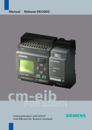
  • 1. cm-eibFOR LOGO! Communication with LOGO! with EIB and the Konnex standard Manual Release 09/2002
  • 2. s CM EIB/KNX LOGO! Expansion Module Manual Chapters Safety Notices 1 Getting to know CM EIB 2 Mounting and wiring the CM EIB 3 Putting the CM EIB into operation 4 Supported functions 5 CM EIB specifications INDEX
  • 3. CM EIB/KNX CM EIB 2 J31069-D1262-U002-A4-7618 Copyright - Siemens AG 1996 to 2002 All rights reserved You may not transfer or duplicate this document or utilize or reveal its contents, unless expressly authorized in writing. In the case of a violation, you will be obliged to pay damages. All rights reserved, in particular in the event that a patent is granted or that a utility model is registered. Disclaimer of liability: We have checked that the contents of this document correctly describe the associated hardware and software. Nonetheless, it is impossible to exclude the possibility of deviations and therefore we cannot guarantee that there are no errors in this document. The information in this document is checked regularly and any necessary corrections are then made in the next release issued. We are of course thankful for any suggestions for improvements.
  • 4. CM EIB/KNX CM EIB J31069-D1262-U002-A4-7618 3 Table of Contents Safety Notices 1 Getting to know CM EIB...................................... 5 1.1 What is the CM EIB? ............................................. 5 1.2 The construction of the CM EIB............................. 6 2 Mounting and wiring the CM EIB/KNX............... 7 2.1 General guidelines ................................................. 7 2.2 Wiring the CM EIB ................................................. 9 2.2.1 Connecting the power supply 10 2.2.2 Connecting the EIB 11 3 Putting the CM EIB into operation ................... 12 3.1 Step-by-step......................................................... 12 3.2 The CM EIB - operational status.......................... 13 3.3 Behavior in case of a fault.................................... 15 4 Supported functions.......................................... 16 4.1 Inputs / Outputs.................................................... 16 4.2 Available communication objects......................... 18 4.3 EIB configuration.................................................. 19 5 CM EIB - Specifications..................................... 22
  • 5. CM EIB/KNX CM EIB 4 J31069-D1262-U002-A4-7618 Indicates that death or severe bodily injury may occur, if the corresponding safety measures are not taken. Safety Notices DANGER WARNING CAUTION CAUTION WARNING Indicates that death, severe bodily injury or substantial material damage will occur, if the corresponding safety measures are not taken. With the warning triangle, this indicates that minor bodily injury may occur, if the corresponding safety measures are not taken. Without the warning triangle, this indicates that material damage may occur, if the corresponding safety measures are not taken. This indicates that an undesirable result or condition may occur, if the corresponding instructions are not observed.
  • 6. CM EIB/KNX CM EIB J31069-D1262-U002-A4-7618 5 1 Getting to know CM EIB 1.1 What is the CM EIB? This is the communications module (CM) for connecting the LOGO! to the EIB bus. The LOGO! communications module has been implemented as a Slave module for the LOGO control module (12/24 or 115/240 Volt). The module supports communication between the LOGO! Master and external EIB devices via an EIB. The CM is a bus participant on the EIB and allows the LOGO! to communicate with other EIB devices using EIB telegrams. What are the capabilities of the CM EIB? The CM transfers EIB telegrams to the LOGO! and LOGO! functions to the EIB. The CM presents the current states of the EIB devices to the LOGO!, which is thus able to use its logical functions und timers to join them together. In the process, the EIB signals can also be combined with the signals of the local LOGO! inputs and outputs. The CM then transmits every change of the output signal via the EIB. The combination of LOGO! and CM EIB gives the user a decentralized controller functionality for the EIB with the capability of setting or changing parameters or operations quickly, simply and without a programming device.
  • 7. CM EIB/KNX CM EIB 6 J31069-D1262-U002-A4-7618 1.2 The construction of the CM EIB 1. Power supply 2. Bus lock slide, interface to the LOGO! 3. The RUN/STOP LED for communication with LOGO! 4. The BUS LED, EIB communications 5. Label for the physical address 6. Inputs - EIB connection 7. Expansion interface to the LOGO! 8. Mechanical coding - pin 9. Programming button
  • 8. CM EIB/KNX CM EIB J31069-D1262-U002-A4-7618 7 2 Mounting and wiring the CM EIB/KNX 2.1 General guidelines • The following guidelines must be observed when mounting and wiring your CM EIB: • When wiring the CM EIB, make certain that you follow all of the applicable and legally binding standards. Observe all of the relevant national and regional regulations when installing and operating the device. Check with the local authorities regarding the standards and regulations that must be observed in your special case. • Make certain that the device is de-energized. • Use only approved bus cables. • The EIB bus cables may also be laid parallel to other lines. • The CM EIB must always be installed as the last module on the right of the LOGO!, since you may not install other expansion modules onto the CM EIB.
  • 9. CM EIB/KNX CM EIB 8 J31069-D1262-U002-A4-7618 Please note: - The CM EIB must have its own voltage supply (24V). NOTE This module may only be mounted and wired by qualified personnel, who know and observe the generally applicable guidelines and applicable regulations and standards. Observe the assembly and disassembly instructions in the LOGO! manual. WARNING The expansion module may only inserted or removed when the power is off.
  • 10. CM EIB/KNX CM EIB J31069-D1262-U002-A4-7618 9 2.2 Wiring the CM EIB To wire the CM EIB, use a screwdriver with a 3 mm wide blade. There is no difference between the terminals of the LOGO! and the EIB. NOTE To protect personnel against unintentional contact with the portions of the CM EIB that are conducting electricity, the appropriate national and local standards must be observed. The CM EIB is a double-insulated switching device. A protective grounding conductor is not necessary.
  • 11. CM EIB/KNX CM EIB 10 J31069-D1262-U002-A4-7618 2.2.1 Connecting the power supply The CM EIB has been designed to serve as a Slave module for the LOGO! controller. It must be connected to a 24 V AC/DC supply voltage. Please observe the relevant instructions that are found in product information that was included with your equipment as well as the technical data regarding the permissible voltage tolerances, mains frequency and current consumption. Connecting How to connect the CM EIB to the power: CM EIB ..... with CM EIB ..... with DC supply AC supply Protect with a 80 mA/slow action fuse, if desired (recommended).
  • 12. CM EIB/KNX CM EIB J31069-D1262-U002-A4-7618 11 2.2.2 Connecting the EIB This connection is made using the two screw terminals (+ and -). + - EIB X 2 3 4 RUN/STOP BUS 6BK1700-0BA00-0AA0 Prog.Prog. red black Only the red – black pair is used, the white – yellow pair is not connected. You can set the CM EIB in the programming mode by pressing on the “Prog ↓” button. NOTE Don't apply too much force when pressing the “Prog ↓” button. When contact has been made, the LED will light up in orange.
  • 13. CM EIB/KNX CM EIB 12 J31069-D1262-U002-A4-7618 3 Putting the CM EIB into operation 3.1 Step-by-step 1. Both the BUS and supply voltage must be present. 2. Connect a PC to the serial EIB interface. 3. Start ETS. Use ETS2 Version 1.2. 4. Use ETS2, V.1.2 to configure the application program. 5. The application program is loaded into the devices via the EIB interface. The application program is available for downloading from the LOGO! homepage (http://www.siemens.de/logo). 6. In ETS, click on “Program Physical Address”. 7. Press the button on the CM EIB to set the CM EIB in programming mode; the LED will light up in orange. 8. When the LED goes out, the physical address has been programmed. You can now note the physical address on the device. The syntax of the physical address: Area / Line / Device XX / XX / XXX
  • 14. CM EIB/KNX CM EIB J31069-D1262-U002-A4-7618 13 9. The application program can now be loaded. Afterwards, the device is ready for operation. + - EIB X 2 3 4 RUN/STOP BUS 6BK1700-0BA00-0AA0 Prog.Prog. red black 10. If multiple CM EIBs have been installed in an EIB system, repeat Steps 1 to 9 for each CM EIB. 11. For further details regarding the EIB installation, please read the corresponding documentation. 3.2 The CM EIB - operational status The CM EIB is a LOGO! expansion module. This module has two LED displays: 1. “RUN/STOP” LED Communication with the LOGO! 2. “BUS” LED EIB-Bus status
  • 15. CM EIB/KNX CM EIB 14 J31069-D1262-U002-A4-7618 The “RUN/STOP” LED will light in green, red or orange. LED Lights In Green (RUN) Red (STOP) Orange The expansion module is communicating with the device on the left. The expansion module is not communicating with the device on the left. The expansion module's initialization phase The “BUS” LED will light in green, red or orange. LED Lights In Green Red Orange Bus connection OK, communication OK, not programming mode Bus connection fault Programming mode active and bus connection OK CM EIB / KNX RUN/STOP BUS + - EIB 6BK1700-0BA00-0AA0 X 2 3 4 L+ M Prog. AC/DC 24V
  • 16. CM EIB/KNX CM EIB J31069-D1262-U002-A4-7618 15 3.3 Behavior in case of a fault LOGO! - Power failure If the power to the LOGO! fails or the communications with the LOGO! Master or the communications partner to the left is interrupted, the outputs will be set to 0. The “RUN/STOP” LED will light in RED after one second. LOGO! - Power returns The LOGO! will startup and the CM will send the parameterized status. CM - Power failure All of the inputs of the EIB's LOGO! Master will be set by the LOGO! Master to 0. CM - Power returns All of the LOGO!Master outputs on the EIB will be updated. The inputs will be – depending on the EIB parameters – read. BUS - Short-circuit or interruption The inputs and outputs will retain their last value until they receive a new one. After 5 seconds, the Bus LED will light in red. BUS - Restored When the BUS is restored, the CM remains neutral, i.e. it does not send any telegrams.
  • 17. CM EIB/KNX CM EIB 16 J31069-D1262-U002-A4-7618 4 Supported functions The CM EIB supports the communications between the LOGO! and EIB and supplies the I/O necessary for the communication via the EIB. 4.1 Inputs / Outputs The standard CM EIB application fills the complete LOGO! process image. I9 I10 I11 I12 Q1 Q2 Q3 Q4 Q5 Q6 Q7 Q8 A 1 A2 A3 ... A8 I13 ... I24 Sensorik Q9 ... Q16 Aktorik 230 RC DM8 AM2 CM EIB/KNX LOGO! 12/24 RC CM-EIB/KNX I1 I2 I3 I4 I5 I6 I7 I8 A1 A2 A3 ... A8 I9 ... I24 Q5 ... Q16 Sensorik Aktorik EIB (Instabus) EIB (Instabus) I1 I2 I3 I4 I5 I6 I7 I8 Q1 Q2 Q3 Q4
  • 18. CM EIB/KNX CM EIB J31069-D1262-U002-A4-7618 17 Sample application: I1 I9 Q9 I14 Q16 Q6 Q1 I13 Q1 Q2 Q3 Q4 Q5 Q6 Q7 Q8 I1 I2 I3 I4 I5 I6 I7 I8 I9I10I11I12 1 2 3 I13 ... I24 Q9 ... Q16 EIB (Instabus) & DM 8 CM EIB/KNXLOGO! 1. To map the LOGO! inputs (I1 to I8and I9 to I12) as outputs on the EIB, these must be joined with free EIB outputs (Q9 to Q16) in the LOGO! application. 2. Operations (basic functions BF / special functions SF) useable within the LOGO! application (e.g. as a feedback signal). 3. To access the LOGO! application (Q1 to Q4 and Q5 to Q8) directly via the bus communications, these must be joined with free EIB inputs (I13 to I24) in the LOGO! application.
  • 19. CM EIB/KNX CM EIB 18 J31069-D1262-U002-A4-7618 4.2 Available communication objects An example of the basic variant – LOGO! CPU and CM EIB without an expansion module: The following communication objects will be available on the EIB / KNX Bus: EIB-Object No. Type (Size) EIS IN / OUT 0 UINT1 EIS1 I9 Input 1 UINT1 EIS1 I10 Input 2 UINT1 EIS1 I11 Input 3 UINT1 EIS1 I12 Input 4 UINT1 EIS1 I13 Input 5 UINT1 EIS1 I14 Input 6 UINT1 EIS1 I15 Input 7 UINT1 EIS1 I16 Input 8 UINT1 EIS1 I17 Input 9 UINT1 EIS1 I18 Input 10 UINT1 EIS1 I19 Input 11 UINT1 EIS1 I20 Input 12 UINT1 EIS1 I21 Input 13 UINT1 EIS1 I22 Input 14 UINT1 EIS1 I23 Input 15 UINT1 EIS1 I24 Input 16 UINT1 EIS1 Q5 Output 17 UINT1 EIS1 Q6 Output 18 UNIT1 EIS1 Q7 Output 19 UINT1 EIS1 Q8 Output 20 UINT1 EIS1 Q9 Output 21 UINT1 EIS1 Q10 Output 22 UINT1 EIS1 Q11 Output 23 UINT1 EIS1 Q12 Output 24 UINT1 EIS1 Q13 Output 25 UINT1 EIS1 Q14 Output 26 UINT1 EIS1 Q15 Output 27 UINT1 EIS1 Q16 Output 28 UINT16 / UINT8 EIS5 / EIS6 AI1 Input 29 UINT16 / UINT8 EIS5 / EIS6 AI2 Input 30 UINT16 / UINT8 EIS5 / EIS6 AI3 Input 31 UINT16 / UINT8 EIS5 / EIS6 AI4 Input 32 UINT16 / UINT8 EIS5 / EIS6 AI5 Input 33 UINT16 / UINT8 EIS5 / EIS6 AI6 Input 34 UINT16 / UINT8 EIS5 / EIS6 AI7 Input 35 UINT16 / UINT8 EIS5 / EIS6 AI8 Input EIS1 (switches) 1 Bit EIS 5 (EIB floating) 2 byte value EIS 6 (EIB floating) 1 byte value
  • 20. CM EIB/KNX CM EIB J31069-D1262-U002-A4-7618 19 4.3 EIB configuration The following application parameters can be set in ETS2, V.1.2: - The number of digital I/Os on the LOGO! Master or expansion modules - The number of analog inputs on the LOGO! Master or expansion modules - The data type for each analog input EIS6 (scaling/8-bit with sign) or EIS5 (EIB-Value Temp/8-bit without sign). In the parameter dialog, you can set the number of inputs and outputs that are already on the LOGO! (including expansion modules) and how many are available via the EIB.
  • 21. CM EIB/KNX CM EIB 20 J31069-D1262-U002-A4-7618 The EIS5 values are converted to a fixed point numerical value with a resolution of 0.1, which equates to a value range of –3276.8 (FFFFh) to +3276.7 (7FFFh). EIS6 values for scaling are accepted, i.e. 0 to 100 % corresponds to an analog value of 0 to 255. Unused analog inputs must be set to “Not Used”.
  • 22. CM EIB/KNX CM EIB J31069-D1262-U002-A4-7618 21 Inputs/Outputs – Special Considerations When using the LOGO! I/O on the CM EIB, you must consider the following. To access the LOGO! outputs (Q1 to Q4) directly via communication over the bus, these must be joined in the LOGO! application with free EIB inputs. To map the LOGO! inputs (I1 to I8) as outputs on the bus, these must be joined in the LOGO! application with free EIB outputs. The outputs on additional I/O modules can also be transferred in parallel via the EIB.
  • 23. CM EIB/KNX CM EIB 22 J31069-D1262-U002-A4-7618 5 CM EIB - Specifications Electrical Data Supply voltage 24 V AC 24 V DC Permissible range -15% +10% -15% +20% Current consumption (power supply) max. 25 mA Current taken from BUS 5 mA EIB data transfer rate 9600 Baud Physical Construction Standard width 2 SU Dimensions (W x H x D) 36 x 90 x 55 mm Weight approx. 50 g Mounting options 35 mm rail wall mounting Operational status display RUN/STOP LED - communications with LOGO! BUS LED – communications with EIB/KNX Controls EIB/KNX programming button S1 Connections LOGO! connection Standard expansion interface for LOGO! 12/24 V and 115/240 V EIB connection (TP 256) max. torque 2 screw terminals (0.5 – 2.5 mm²) 0.5 Nm Power supply max. torque 2 screw terminals (0.5 – 2.5 mm²) 0.5 Nm Standard bus lines to use YCYM or J-Y(ST)Y (2 x 2 x 0.8 mm²) Digital inputs (I) - virtual max. 16 Digital outputs (Q) - virtual max. 12 Analog inputs (AI) - virtual max. 8 Max. group addresses 64 Max. associations 64 Environmental Conditions Permissible operating temperature 0°C to +55°C free convection Storage and transport temperatures -40°C to +70°C Humidity 95% at +25°C
  • 24. CM EIB/KNX CM EIB J31069-D1262-U002-A4-7618 23 Safety Protection standard IP 20 Radio interference suppression EN 55011 (Limit Value Class B) Certification CE EIB/KNX UL 508 VDE 0631 IEC 61131-2 Overvoltage protection Fuse 80 mA slow action fuse Order Data LOGO! Expansion Module EIB/KNX CM 6BK1700-0BA00-0AA0
  • 25. CM EIB/KNX CM EIB 24 J31069-D1262-U002-A4-7618 INDEX EIB European Installation Bus EIS EIB Interoperability Standard ETS EIB Tool Software KNX Standard of the Konnex Association
  • 26. Siemens Aktiengesellschaft Automation and Drives Systems Engineering PO. 2355, D-90713 Fürth w w w . s i e m e n s . c o m Order No. J31069-D1262-U002-A4-7618