

Recommended
Recommended
More Related Content
What's hot
What's hot (18)
Viewers also liked
Similar to Wireless sensor network
Similar to Wireless sensor network (20)
Recently uploaded
Recently uploaded (20)
Wireless sensor network
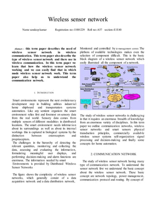
- 1. Wireless sensor network Name sandeep kumar Registration no:-11001229 Roll no:-A57 section:-E1E40 Abstract— this term paper describes the need of wireless sensor network in wireless communication. This term paper also describe the type of wireless sensor network and there use in wireless communication. In this term paper we learn that how the wireless sensor network working and we can easily find that in which mode wireless sensor network work. This term paper also help us to understand the communication network. I. INTRODUCTION Smart environments represent the next evolutionar y development step in building utilities industr ia l home shipboard and transportation systems automation. Like any sentient organism the smart environment relies first and foremost on sensory data from the real world. Sensory data comes from multiple sensors of different modalities in distributed locations. The smart environment needs informa t ion about its surroundings as well as about its internal workings this is captured in biological systems by the distinction between exteroceptors and proprioceptors. The challenges in the hierarchy of: detecting the relevant quantities, monitoring and collecting the data, assessing and evaluating the informat ion, formulating meaningful user displays, and performing decision-making and alarm functions are enormous. The information needed by smart Environments is provided by Distributed Wireless Sensor Networks The figure shows the complexity of wireless sensor networks, which generally consist of a data acquisition network and a data distribution network, Monitored and controlled by a management center. The plethora of available technologies makes even the selection of component difficult. This is the basic block diagram of a wireless sensor network which easily illustrated all the component of a network. The study of wireless sensor networks is challenging in that it requires an enormous breadth of knowledge from an enormous variety of disciplines. In this term paper we outline communication networks, wireless sensor networks and smart sensors physical transduction principles, commercially available wireless sensor systems self-organization signal processing and decision-making and finally some concepts for home automation. 2. COMMUNICATION NETWORK The study of wireless sensor network having many type of communication network. To understand the sensor network first we understand the basic concept about the wireless sensor network. These basic concept are network topology, power manageme nt, communication protocol and routing. By concept of
- 2. 2.1 NETWORK TOPOLOGY The basic issue in communication networks is the transmission of messages to achieve a prescribed message throughput Qos. (Quantity of Service). The installation environment economic considerations and the application, one of several basic network topologies may be used. A communication network is composed of nodes, each of which computing the power and transmit or receive the message over communication links ie wireless or cabled. Mess network are distributly networks that generally allow transmission only to a nodes nearest neighbors. The nodes in these networks are generally identical, so that mesh nets are also referred to as peer-to-peer (see below) nets. Mesh nets can be good models for large-scale networks of wireless sensors that are distributed over a geographic region, personnel or vehicle security surveillance systems. Note that the regular structure reflects the communicat ions topology; the actual geographic distribution of the nodes need not be a regular mesh. Since there are generally multiple routing paths between nodes these nets are robust to failure of individual nodes or links. An advantage of mesh nets is that, although all nodes may be identical and have the same computing and transmission capabilities, certain nodes can be designated as ‘group leaders’ that take on additiona l functions. If a group leader is disabled another group will take these duty. All nodes of the star topology are connected to a single hub node. The hub requires greater message handling, routing, and decision-making capabilities than the other nodes. If a communication link is cut, it only affects one node. However, if the hub is incapacitated the network is destroyed. In the ring topology all nodes perform the same function and there is no leader node. Messages generally travel around the ring in a single direction. However, if the ring is cut, all communication is lost In the bus topology messages are broadcast on the bus to all nodes. Each node checks the destination address in the message header, and processes the messages addressed to it. The bus topology is passive in that each node simply listens for messages and is not responsible for retransmitting any messages Here the fig of all the topology that is described:- 2.2 COMMUNICATION PROTOCOL OR ROUTING The topic communication protocol and routing is required much study to understand. There are some basic concept which are used in communica t ion routing and protocol these basic protocol are:- 1. Header: - Each message generally has a header identifying its source node, destination node, length of the data field, and other information. This is used by the nodes in proper routing of the message. In encoded messages, parity bits may be included. In packet routing networks, each message is broken into packets of fixed length. The packets are transmitted separately through the network and then reassembled at the destination. The fixed packet length makes for easier routing and satisfaction of QoS. Generally, voice communications use circuit switching, while data transmissions use packet routing. 2. Switching:- Most computer networks use a store-and-forward switching technique to control the flow of information . Then, each
- 3. time a packet reaches a node, it is completely buffered in local memory, and transmitted as a whole. More sophisticated switching techniques include wormhole, which splits the message into smaller units known as flow control units or flits. The header flit determines the route. As the header is routed, the remaining flits follow it in pipeline fashion. This technique currently achieves the lowest message latency. Another popular switching scheme is virtual-cut-through. Here, when the header arrives at a node, it is routed without waiting for the rest of the packet. Packets are buffered either in software buffers in memory or in hardware buffers, and various sorts of buffers are used including edge buffers central buffers etc. 3. Multiple access control: - When mult iple nodes desire to transmit, protocols are needed to avoid collisions and lost data. In the ALOHA scheme, first used in the 1970’s at the University of Hawaii, a node simply transmits a message when it desires. If it receives an acknowledgement, all is well. If not, the node waits a random time and re-transmits the message. 4. Routing: - Since a distributed network has mult iple nodes and services many messages, and each node is a shared resource, many decisions must be made. There may be multiple paths from the source to the destination. Therefore, message routing is an important topic. The main performance measures affected by the routing scheme are throughput (quantity of service) and average packet delay (quality of service). Routing schemes should also avoid both deadlock and lovelock. Routing methods can be fixed adaptive centralized, distributed broadcast etc. Perhaps the simplest routing scheme is the token ring . Here, a simple topology and a straightforward fixed protocol result in very good reliability and precomputable QoS. A token passes continuously around a ring topology. When a node desires to transmit, it captures the token and attaches the message. As the token passes, the destination reads the header, and captures the message. In some schemes, it attaches a ‘message received’ signal to the token, which is then received by the original source node. Then, the token is released and can accept further messages. The token ring is a completely decentralized scheme that effectively uses TDMA. Though this scheme is very reliable, one can see that it results in a waste of network capacity. The token must pass once around the ring for each message. Therefore, there are various modifications of this scheme, including using several tokens, etc. 2.3 POWER MANAGEMENT There is a focus on increasing the lifetimes of sensor nodes through power generation, power conservation, and power management. Current research is in designing small MEMS (micro electromechanical systems) RF components for transceivers, including capacitors, inductors, etc. The limiting factor now is in fabricating micro-sized inductors. Another thrust is in designing MEMS power generators using technologies including solar, vibration (electromagnetic and electrostatic), thermal, etc. This figure will show the concept of power management in wireless sensor network with the use of mems The required transmission power increases as the square of the distance between source and destination. Therefore, multiple short message transmission hops require less power than one long hop. In fact, if the distance between source and destination is R the power required for single-hop transmission is proportional to R 2 . If
- 4. nodes between source and destination are taken advantage of to transmit n short hops instead, the power required by each node is proportional to 2 R /n 2 . This is a strong argument in favor of distributed networks with multiple nodes, i.e. nets of the mesh variety. 2.4 Network Structure and Hierarchical Networks Routing tables for distributed networks increase exponentially as nodes are added. An n mesh network has nm links, and there are multiple paths from each source to each destination. Hierarchica l network structures simplify routing, and also are amenable to distributed signal processing and decision-making, since some processing can be done at each hierarchical layer. It has been shown in the figure that a fully connected network has NP-hard complexity, while imposing routing protocols by restricting the allowed paths to obtain a reentrant flow topology results in polynomial complexity. Such streamlined protocols are natural for hierarchical networks. 2.5 SIGNAL PROCESSING AND DECISION MAKING 2.5.1 SIGNAL CONDITIONING:- Signals coming from MEMS sensors can be very noisy, of low amplitude, biased, and dependent on secondary parameters such as temperature. Moreover, one may not always be able to measure the quantity of interest, but only a related quantity. Therefore signal conditioning is usually required. SC is performed using electronic circuitry, which may convenient ly be built using standard VLSI fabrication techniques in situ with MEMS sensors. This figure will help us to understand that how the signal is used through the analog low pass filter.by using analog filter we are able to measuring the quantity of interst. A real problem with MEMS sensors is undesired sensitivity to secondary quantities such as temperature. Temperature compensation can often be directly built into a MEMS sensor circuit. In the figure above showing a 3x3 array of IGEFET sensors, A basic technique for improving the signal-to-noise ratio (SNR) is low-pass filter ing, since noise generally dominates the desirable signals at high frequencies. Shown in the figure is an analog LPF that also amplifies, constructed from an operational amplifier. Such devices are easily fabricated using VLSI semiconductor techniques. The time constant of this circuit is CR2 .The transfer function of this filter is with 3 dB cutoff frequency given by rad. and gain given by. Here, s is the Laplace transform variable. The cutoff frequency should be chosen larger than the highest useful signal frequency of the sensor. 2.5.2 DIGITAL SIGNAL PROCESSING Sensor fusion is important in a network of sensors of different modalities. A distributed vehicle/personnel surveillance network might include seismic, acoustic, infrared motion, temperature, and magnet ic sensors. The standard DSP tool for combining the information from many sensors is the Kaman Filter .The Kaman Filter is used for communications, navigation, feedback control, and elsewhere and provides the accuracy that allowed man to navigate in space and eventually to reach the moon and more recently to send probes to the limits of the Solar System. A properly designed Kaman Filter allows one to observe only a few quantities, or measured outputs, and then reconstruct or estimate the full internal state of a system. It also provides low-pass filter ing
- 5. functions and amplification, and can be constructed to provide temperature compensation, common mode rejection, zero offset correction, etc. The discrete-time Kaman Filter. Where the sensed outputs are in a vector zk, the control inputs to the system being observed are in vector UK, and the estimates of the internal states are given by the vector. Note that the number of sensed outputs can be significantly less than the number of states one can estimate. In this filter, matrices A and B represent the known dynamics of the sensed system, and the sensed outputs are given as a linear combination of the states by, where H is a known measurement matrix. The Kalman gain K is determined by solving a design equation known as the Rickety Equation. The Kalman Filter is the optimal linear estimator given the known system properties and prescribed corrupting noise statistics. kxˆkkHxz _ Distributed signal processing is the most effic ie nt means of computation in a network of distributed signal-processing nodes. The theory of Decentralized Kalman Filtering provides a formal mechanism for apportioning sensor filter ing, reconstruction, and compensation tasks among a hierarchically organized group of nodes. Other DSP tools include techniques used in spectrum analysis, speech processing, stock market analysis, etc. Statistical methods allow regression analysis, correlation analysis, principal component analysis, and clustering. Also available are a wide range of techniques based on neural network properties of classification, association, generalization, and clustering. Decision-making paradigms include fuzzy logic, Bayesian decision-making, Dumpster- Shafer, diagnostic/prescription-based schemes as used in the medical field, and so on. The Math Works software MATLAB has extensive capabilities in all these areas, and specialized Toolboxes provide powerful tools for DSP and decision-making for distributed wireless sensor networks. 2.5.3 DECISION MAKING USER INTERFACE Many software products are available to provide advanced DSP, intelligent user interfaces, decision assistance, and alarm functions. Among the most popular, powerful, and easy to use is National Instruments lab VIEW software. Available are toolkits for camera image processing, machiner y signal processing and diagnostics, sensor equipment calibration and test, feedback control, and more. The figure shows a Lab VIEW user interface for monitoring machinery conditions over the Internet for automated maintenance scheduling functions. Included are displays of sensor signals that can be selected and tailored by the user. The user can prescribe bands of normal operation, excursions outside of which generate alarms of various sorts and severity. 2.6 BUILDING AND HOME AUTOMATION The figure shows how networks of various sorts might interact in the smart home environment. An excellent reference for this section is Frank [2000]. There are many available protocols for networking of the smart home, and it is not necessary to develop new protocols on one’s own for commercia l ly acceptable systems. The BACnet protocol has been developed by the building automation industry to provide a standard for interconnecting networks for building sensing and control. Networks that can be used include Ethernet, MS/TP, and LonWorks. Building energy management standards are being developed by the American Society of Heating, Refrigeration, and Air-Conditioning Engineers (ASHRAE). A major driver for the smart home is the power distribution industry, which could save enormous sums with demand-side regulation and automated remote meter reading. The Intelligent Building Institute has been a force in developing appropriate standards.
- 6. Several automotive protocols have been developed, and some of these are useful also for building control. CAN is a serial communications protocol developed for automotive multiplex wiring systems, and has been adopted in industrial applications by manufacturers such as Allen-Bradley (in the Device NET system) and Honeywell (in SDS). CAN supports distributed real-time control with a high level of security, and is a MultiMate protocol that allows any node in the network to communicate with any other node. Supported are user-defined message prioritization, multiple access/collision resolution, and error detection. The Lon Works protocol, developed by Echelon Corp is very convenient for industrial and consumer applications. It supports all seven layers of the OSI/RM model, and supports fieldbus requirements, arbitration, and message coding. Lon Works operates on a peer-to-peer bus network basis. Devices in a Lon Works network communicate using Lon Talk. This language provides a set of services that allow the application program in a device to send and receive messages from other devices over the network without needing to know the topology of the network or the names, addresses, or functions of other devices. The Lon Works protocol can optionally provide end-to-end acknowledgement of messages, authentication of messages, and priority delivery to provide bounded transaction times. Support for network management services allows for remote network management tools to interact with devices over the network, including reconfiguration of network addresses and parameters, downloading of application programs, reporting of network problems, and start/stop/reset of device application programs. Lon Works networks can be impleme nted over basically any medium, including power lines, twisted pair, radio frequency (RF), infrared (IR), coaxial cable and fiber optics. 2.7 COMMERICALY AVAILABLE WIRELESS SENSOR SYSTEMS Many commercially available wireless communications nodes are available including Lynx Technologies, and various Bluetooth kits, including the Casira devices from Cambridge Silicon Radio, CSR. Crossbow Berkeley Motes may be the most versatile wireless sensor network devices on the market for prototyping purposes. Crossbow (http://www.xbow.com/) makes three Mote processor radio module families– MICA [MPR300] (first generation), MICA2 [MPR400] and MICA2- DOT [MPR500] (second generation). Nodes come with five sensors installed- Temperature, Light, Acoustic (Microphone), Acceleration/Seismic, and Magnetic. These are especially suitable for surveillance networks for personnel and vehicles. Different sensors can be installed if desired. Low power and small physical size enable placement virtually anywhere. Since all sensor nodes in a network can act as base stations, the network can self-configure and has multi-hop routing capabilit ies. The operating frequency is ISM band, either 916 MHz or 433 MHz, with a data rate of 40 Kbits/sec. and a range of 30 ft. to 100 ft. Each node has a low power microcontroller processor with speed of 4MHz, a flash memory with 128 Kbytes, and SRAM and EEPROM of 4K bytes each. The operating system is Tiny-OS, a tiny micro-threading distributed operating system developed by UC Berkeley, with a NES-C (Nested C) source code language (similar to C). Installation of these devices requires a great deal of programming. This is the micro strain sensor which is available in these days. Micro strain’s X-Link Measurement System may be the easiest system to get up and running and to program. The frequency used is 916 MHz, which lies in the US license-free ISM band. The sensor nodes are multi-channel, with a maximum of 8 sensors supported by a single wireless node. There are three types of sensor nodes – S-link (strain gauge), G-link (accelerometer), and V-link (supports any sensors generating voltage differences). The sensor nodes
- 7. have a pre-programmed EPROM, so a great deal of programming by the user is not needed. Onboard data storage is 2MB. Sensor nodes use a 3.6-volt lithium ion internal battery (9V rechargeable external battery is supported). A single receiver (Base Station) addresses multiple nodes. Each node 16 has a unique 16-bit address, so a maximum of 2 nodes can be addressed. The RF link between Base Station and nodes is bi-directional and the sensor nodes have a programmable data logging sample rate. The RF link has a 30 meter range with a 19200 baud rate. The baud rate on the serial RS-232 link between the Base Station and a terminal PC is 38400. lab VIEW interface is supported REFERENCES:- 1. E. Altman, T. Basra, T. Jimenez, and N. Shimkus, “Comp etitive routing in networks with p oly nomial costs,” IEEE Trans. Automat. Control, vol. 47, no. 1, pp. 92-96, 2002. 2. J. Diatom, “A necessary and sufficient condition for deadlock-free routing in cut-through and store-and-forward networks,” IEEE Trans Parallel and Diatribe. Systems, vol. 7, no. 8, pp. 841- 854, Aug. 1996. 3. E.S. Kelsea, C.P. Brothers, C.P. Howe, et al., “Integrated circuit micro sensor for selectively detecting nitrogen dioxide and isopropyl methyl phosphate,” Thin Solid Films, vol. 220, pp. 30-37. 1992.