1) The document describes lab experiments to demonstrate the working principles of a DC motor, alternator, and induction motor by connecting various voltage sources and observing changes in speed, current, and voltage generation.
2) Additional experiments connect an autotransformer and variable DC power supply to a oscilloscope to observe sinusoidal AC voltages and varying DC voltages.
3) Key measurements include armature current, motor speed, alternator output voltage, and voltage readings on multimeters and oscilloscopes.
Booking open Available Pune Call Girls Pargaon 6297143586 Call Hot Indian Gi...
Content beyond syllabus
1. Content Beyond Syllabus
Basic Electrical Engineering: 18ELE13
Faculty; Dr. B G Shivaleelavathi
Branch/ Sem./ Section: CSE/1/A
Date: 24/12/2018 and 26/12/2018
CO: C103.4
PO: PO12
To demonstrate the working of a DC motor, Alternator and Induction Motor:
In the lab separately excited DC motor is available:
Connect 220V DC supply to the field ,
And 220v DC to the armature of the DC motor.
Keep the armature supply to 0 volts and gradually vary the Armature voltage in steps of 120 V
and observe the speed of the motor on the speedometer and the armature current in the ammeter.
Tabulate the results and give your conclusions. Note that the speed increases with the increase in
the armature voltage.
Now reduce the armature voltage and remove the field excitation.
Connect 220v DC excitation to the field of the alternator and 220v to field of the DC motor and
vary the armature voltage in steps of 40 Volts and note the Ac voltage generated(mechanical to
electrical) at the line terminals of the Alternator by connecting an digital multimeter also connect
lamp load to the phase and line and see that lamp glows. Observe the line voltages on the two
channels of the CRO.
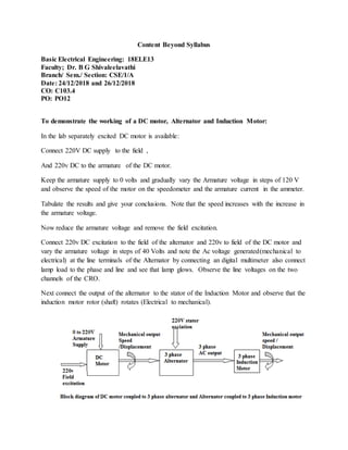
Next connect the output of the alternator to the stator of the Induction Motor and observe that the
induction motor rotor (shaft) rotates (Electrical to mechanical).
2. To demonstrate understanding ofAC voltage and Dc Source:
Connect the AC main supply to a Autotransformer keep the auto transformer to minimum
position that is 0volts. Now connect a power scope to the output terminals of the
autotransformer. Vary the supply and adjust to 220v and observe the Sinusoidal voltage on the
CRO. Find the peak voltage on the CRO and RMS voltage using the Voltameter(AC).
Similarly Connect the Regulated Dc power supply to the AC supply and connect a CRO to the
output terminals of the Regulated Power supply. Vary the RPS foltage that the potentiometer
from 0v to 32v insteps and oabser that the line on CRO shifts from 0 volts per division to some
volts per division.
Voltage measured = volts per division x number of division.
On DC voltmeter it is directly indicated .
Figure: DC Voltage source
Figure: AC Voltage