The NDT practitioner’s dream – a validated call!
•
1 like•513 views

Over the years, I’ve often made calls on weld inspection which have resulted in being ground out and re-welded. Although able locate, orientate and size indications, never having the luxury of knowing how accurate my evaluations were, intrigued me. Until my last assignment.

Recommended
More Related Content
Viewers also liked
Viewers also liked (13)
Similar to The NDT practitioner’s dream – a validated call!
Similar to The NDT practitioner’s dream – a validated call! (15)
Recently uploaded
Recently uploaded (20)
The NDT practitioner’s dream – a validated call!
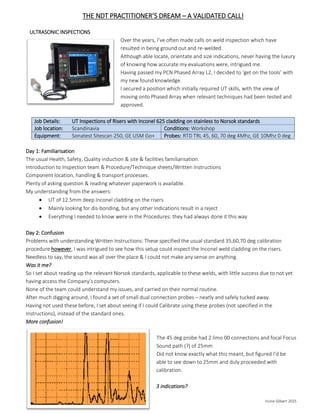
- 1. THE NDT PRACTITIONER’S DREAM – A VALIDATED CALL! Irvine Gilbert 2015 ULTRASONIC INSPECTIONS Over the years, I’ve often made calls on weld inspection which have resulted in being ground out and re-welded. Although able locate, orientate and size indications, never having the luxury of knowing how accurate my evaluations were, intrigued me. Having passed my PCN Phased Array L2, I decided to ‘get on the tools’ with my new found knowledge. I secured a position which initially required UT skills, with the view of moving onto Phased Array when relevant techniques had been tested and approved. Job Details: UT Inspections of Risers with Inconel 625 cladding on stainless to Norsok standards Job location: Scandinavia Conditions: Workshop Equipment: Sonatest Sitescan 250, GE USM Go+ Probes: RTD TRL 45, 60, 70 deg 4Mhz, GE 10Mhz 0 deg Day 1: Familiarisation The usual Health, Safety, Quality induction & site & facilities familiarisation. Introduction to Inspection team & Procedure/Technique sheets/Written Instructions Component location, handling & transport processes. Plenty of asking question & reading whatever paperwork is available. My understanding from the answers: UT of 12.5mm deep Inconel cladding on the risers Mainly looking for dis-bonding, but any other indications result in a reject Everything I needed to know were in the Procedures: they had always done it this way Day 2: Confusion Problems with understanding Written Instructions: These specified the usual standard 35,60,70 deg calibration procedure however, I was intrigued to see how this setup could inspect the Inconel weld cladding on the risers. Needless to say, the sound was all over the place & I could not make any sense on anything. Was it me? So I set about reading up the relevant Norsok standards, applicable to these welds, with little success due to not yet having access the Company’s computers. None of the team could understand my issues, and carried on their normal routine. After much digging around, I found a set of small dual connection probes – neatly and safely tucked away. Having not used these before, I set about seeing if I could Calibrate using these probes (not specified in the Instructions), instead of the standard ones. More confusion! The 45 deg probe had 2 limo 00 connections and focal Focus Sound path (?) of 25mm Did not know exactly what this meant, but figured I’d be able to see down to 25mm and duly proceeded with calibration. 3 indications?
- 2. THE NDT PRACTITIONER’S DREAM – A VALIDATED CALL! Irvine Gilbert 2015 I did not know what I was seeing, and after further investigation discovered this was a TRL probe, of which I knew absolutely nothing. Help! Turns out, neither did the others on the team. Checked with the in-house Level 3, who insisted all relevant information was in the Procedures, Techniques & Work Instructions. I was not comfortable with standard probes being used and elected to focus on MPI & DP Inspections, until I was confident enough of everything related to UT, for these specific inspections. Day 3: Help arrives. I contacted a few people in my network to find out exactly what these TRL probes are and how would I use them meaningfully. A very good friend explained what I was looking at, and using this knowledge I set about calibration (tuning for ‘maximum smoke’), then checking to see if I can find anything on the test pieces. Hoorah! I was able to detect and size the drilled holes on the test pieces, with surprising accuracy. I explained and demonstrated my results to the in-house L3, who expressed concerns of previous on goings. Not wanting to get into any politics or upset anyone, I simply put forward my case: I can detect and accurately size indications on the test pieces, by using a combination of existing equipment, procedures and know-how. He agreed, and would take care of relevant paperwork. Onwards: I find Indications Confident that I now have the right tools & know-how, the rest of Day 3 and onwards was spent productively. Earlier, I was told that all cladding was 12.5mm – Not so! A trip to the weld shop proved my point. My first discovery was that the cladding depth on the risers varied: 12.5mm and 25mm, depending on customer specifications. Nothing about these differences on Procedure/Technique Sheets. Raised a few eyebrows!
- 3. THE NDT PRACTITIONER’S DREAM – A VALIDATED CALL! Irvine Gilbert 2015 The Fun Starts! After Inspecting of a few risers, I find indications & duly marked these out. Unsurprisingly, this created a lot of attention from all concerned. Once I demonstrated my findings to the L3, it was decided to get the Main Contracting Company (whom I was working for), to double-check. Naturally, I have no problems with this: After all, I needed to be sure as well. Relief! This was duly carried out by an experienced TRL inspector, who concurred with my findings What Next? Welding stops, I’ve now doubled my workload – inspecting all risers which had previously (to me), been inspected, whilst decisions are made elsewhere, moving forward. It gets worse! I find more & more indications. A decision is made to machine the riser around where the indication was found, ready to be re-welded. In the meantime, it was discovered that one of the welding machines had a few ‘technical issues’. Bingo! Machined proof of the indication, came as a great relief. Although brought a smile to my face – I was well aware there would be massive resultant fall-out. I was however, confident that as an NDT practitioner – it is my job to help the organisation meet their Quality Assurance commitments, and my contribution was useful.
- 4. THE NDT PRACTITIONER’S DREAM – A VALIDATED CALL! Irvine Gilbert 2015 The Confidence Grows My UT measurements were noted as above. What this is saying is that the Indication is: 200mm from the central datum line (taken from the Component’s Serial number) 90 mm length 105mm from start of weld 9mm depth from the surface 3-4mm through Characterized as lack of bond - rejectable I later discovered the Inconel filler wire was 1.2mm diameter, consistent with 3 or so passes. Result: Wins all round! An issue with the welding machine was indeed found and rectified. Inspection Procedures & Techniques were adapted to include my input. I shared my knowledge with other inspectors – and to be fair to them: They followed their predecessors. My Phased Array training, coupled with help from outside colleagues, equipped me with an ability to visualize and understand the indications better. Satisfaction of my contribution to the QA system and more important: A satisfied customer and new friends! Acknowledgements: My thanks to Tim Stubbs for all his help.