Tofd tanker inspection development
•
2 likes•562 views

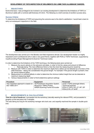
To determine the limitations of TOFD and assuming the outcome was to the client’s satisfaction: I would lead a team to carry out subsequent inspections in the field. The following is a brief overview of another success story.

Recommended
Recommended
More Related Content
What's hot
What's hot (20)
Similar to Tofd tanker inspection development
Similar to Tofd tanker inspection development (20)
Recently uploaded
Recently uploaded (20)
Tofd tanker inspection development
- 1. DEVELOPMENT OF TOFD INSPECTION OF WELDMENTS ON 5.5MM THICK ALUMINIUM TANKERS. Irvine Gilbert 2015 1 OBJECTIVES Some time back, I was privileged to be involved in an exciting development to determine the limitations of TOFD on Aluminium welds with a nominal wall thickness of 5.5mm. The following is a brief overview of another success story. Success Criteria: To determine the limitations of TOFD and assuming the outcome was to the client’s satisfaction: I would lead a team to carry out subsequent inspections in the field. The development was carried out in the Benelux and field inspections abroad. Our development leader is a highly respected Level 3 professional (who is also a very good friend), together with PCN L2 TOFD Technician, supported by myself providing Project Management & Scanner Technician duties. In order to determine the limitations of the TOFD technique, the following tests were carried out: 1. Measure the sound velocity on the extrusion and plate, in order to find the values and amount of difference o Rationale being: The more difference there is, then the more the measuring error would be. 2. Measure with TOFD in order to determine the maximum depth that a defect can be detected as a function of the plate thickness – taking into consideration the groove length. For example: If the groove length is present, then we cannot measure below. 3. Measurement on artificial defects in order to determine the minimum defect height that can be detected at maximum measuring depth 4. Various measurements in order to find & determine optimum settings Procedure Equipment Personnel This inspection approach is based on ISO 10863:2011 TD Pocketscan Acquisition System, Rhosonics 15MHz Probes, WREN Scanning Frame & Encoder Level 3 TOFD (amongst others) Technical Authority PCN L2 TOFD, PA, UT, MT, DP PCN L2 PA, UT & MT 2 MEASUREMENTS & CALCULATIONS Time for a bit of hands-on: I proceeded into the workshop (naturally wearing the relevant PPE), and proceeded to gingerly cut the test piece into 3 samples. This was taking too long for the workshop manager who took over, and expertly machined the sample in double quick time
- 2. DEVELOPMENT OF TOFD INSPECTION OF WELDMENTS ON 5.5MM THICK ALUMINIUM TANKERS. Irvine Gilbert 2015 Using 0 degree probe we achieved the following measurements SAMPLE # PLATE THICKNESS TIME 1ST BACKWALL TIME 4TH BACKWALL 1 4.6mm 1.82 micro sec 6.16 micro sec 2 4.65mm 1.84 micro sec 6.20 micro sec 3A 9.32 mm 3.28 micro sec 11.99 micro sec 3B 9.35mm 3.28 micro sec 12.01 micro sec Using the following logic: Plate thickness x No. skips from 1st measurement to 4th measurement = Total distance covered (mm) We know that the number of skips from 1st measurement to 4th measurement = 6 We can measure the total distance covered from 1st to 4th measurements (mm) Also the time taken to do those skips = Time from 4th - 1st (micro seconds (10-6 ) Calculations SAMPLE TOTAL DIST TIME TAKEN VELOCITY No. mm Micro sec m/s 1 4.6x6= 27.6 6.16-1.82= 4.34 27.6 (x 10−3 ) / 4.34 (x10-6 ) = 6360.0 This procedure was repeated for all four samples to give an average velocity (Plate 3 having 2 measuring points): 6360.0+6339.0+6420+6426.1 / 4 = 6386.25 m/s +/- 47 m/s. 2.1 REFERENCE PLATE Sample 3, was designated the reference plate, which would be used to calibrate for subsequent inspections 1mm dia middle hole drilled (A) T 0.5 +/- 0.3 mm deep x 1mm wide notch underneath Scan in direction of the weld 1mm dia 1.15mm (+/- 0.5 mm) from bottom (B) @ ¾ Thickness (T) We discovered that due to discrepancies in sound velocity caused by the orientation of the grain structure: Scanning in the direction of the weld gave the lowest sound velocity – thereby providing the best results. Detection of the side drilled holes on this piece was unsatisfactory, due to the thinness of the plate. The height of the notch, however could be detected and measured at 0.7mm. 2.2 TEST PIECE WELDS Side drilled holes were inserted into a designated Test Piece, which would then be used for sensitivity checks. 1mm dia. Bottom Hole @ ¾ T +/- 0.5 mm 1mm dia. Middle Hole @ 1/2T+/- 0.5 mm
- 3. DEVELOPMENT OF TOFD INSPECTION OF WELDMENTS ON 5.5MM THICK ALUMINIUM TANKERS. Irvine Gilbert 2015 3 RESULTS. 3.1 SCAN ON TEST PIECE (PLATE 3) The scans demonstrated that the maximum thickness that can be inspected is up to the depth of the adjacent groove. The holes are clearly detected and the following values were measured for Plate 3 (reference piece) Plate 3 results File name/description hole Depth Top of indication Bottom of indication Throughwall height plate 3 1mm sdh plate bottom 240913 IW_TOFD1.scn ¾ T 3.95 3.95 5.38 1.4 plate 3 1mm sdh plate bottom 240913 IW_TOFD2.scn ¾ T 3.95 5.25 1.3 plate 3 1mm sdh plate middle 240913 IW_TOFD1.scn ½ T 3.22 3.42 4.72 1.3 plate 3 1mm sdh plate middle 240913 IW_TOFD2.scn ½ T 3.22 3.61 4.75 1.4 Height of indication was determined at 1.4mm with an accuracy +/- of 0.5mm Detection threshold of +/- 0.5mm was determined. 3.2 SCAN VIEWS OF TEST PIECE WELDS WITH DEFECT The following samples were subsequently tested (Labelled Plate1 & Plate 2). These samples have known defects and also have a protective coating coated The test scans were conducted using optimum settings which have been determined & included in the Procedure 4 SUMMARY OF LABORATORY RESULTS. 1. The sound velocity variation of the samples is less than 10% and will not significantly influence the depth measuring accuracy. 2. Maximum thickness that can be inspected is up to the depth of the adjacent groove 3. The side drilled holes could be detected and sized. The estimated accuracy for depth measurement is 0.5mm. The notch could be detected and sized. The estimated detection threshold id 0.5mm 4. The best set up was established and described in the Procedure
- 4. DEVELOPMENT OF TOFD INSPECTION OF WELDMENTS ON 5.5MM THICK ALUMINIUM TANKERS. Irvine Gilbert 2015 5 IN THE FIELD Equipped with the tools and skills necessary to carry out inspections, we flew off to where the tankers were stationed, and set about site establishment. A scan plan was drawn up (below), and relevant H&S put in place: Risk Assessments, PPE, Working at heights, etc. A trip to the nearest Garden Centre, we acquired a pressurized water bottle and some thin bore water hose: Makes the perfect couplant feeder. Armed with a licence to operate a Cherry-Picker, and Safety harnesses: We were good to go! The Client approved our inspection plan, and was eager to validate the results. This would be achieved by cutting out plates that were inspected and then cutting through where the indications were marked. 6 RESULTS: WINS ALL ROUND - AGAIN We achieved our objectives: o The Development was successful in delivering a Technique which was repeatable The client was happy that we were able to acquire accurate data which would enable them process this into relevant engineering information, which would be beneficial to their business/engineering processes. I gained valuable experiences including: o Project Management responsibility for delivering both Development and Field trials o Insights into the inspection development & validation process Again, A satisfied customer and more new friends! At position 424mm: Top of indication=3.423mm from top surface Bottom of indication = 5.254mm from top surface Giving a through wall height of 5.254-3.423= 1.831mm After cutting, Actual measurement was deemed to be 2mm