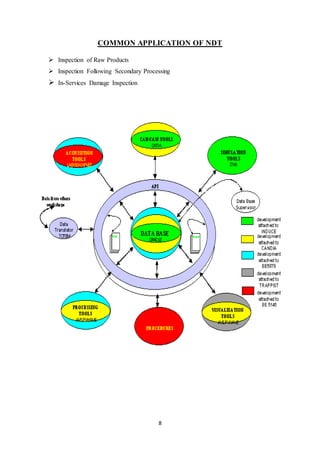
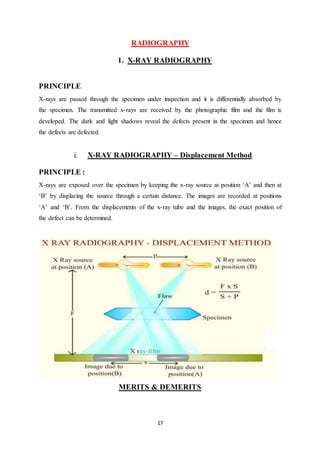
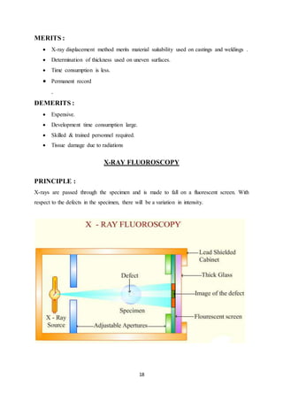
1. 1
A
SEMINAR REPORT
ON
NON DESTRUCTIVE TESTING
A THESIS SUBMITTED IN PARATIAL FULFILLMENT OF THE
REQUIREMENTS FOR THE DEGREE OF
Bachlor of Technology
In
Mechanical Engineering
By
Jamshed Alam
Under Guidance
Mr.Prabhakar Gupta
(Asst. Prof.)
Department of Mechanical Engineering
Mohammad Ali Jauhar University
Rampur-244901 U.P. India
2. 2
ACKNOWLEDGEMENT
I wish to express my gratitude and heartful thanks to my seminar In-charge Mr.Shailendra
Kumar Neeraj and guide Mr. Prabhakar Gupta department of mechanical engineering ,
MAJU, Rampur , for their constructive and helpful suggestions and guidance. I am really
thankful for their support and inspiration throughout the making of this report. I am also duly
acknowledged for their continuous Encouragement which has been motivating force in
moulding the seminar report. I am immensely grateful and indebted to them for believing in
me throughout the course of study.
Immense thanks to the department of mechanical engineering for Helping me in
innumerable ways. My most humble regards to my parents for extending full co-operation.
I am very thankful for to almighty GOD who is source of energy within me.
JAMSHED ALAM
Roll No. 1601050007
B.Tech 3rd Year (M.E.)
3. 3
MOHAMMAD ALI JAUHAR UNIVERSITY
(Established Under UP Act NO. 19.6.2006)
Jauhar Nagar , Post-Sigan Khera, Rampur (U.P.)
Phone No: 0595-2328786,
Website – www.jauhar university.edu.in
Email- vcmajuiv@live.com
CERTIFICATE
This is to certify that Jamshed Alam a student of B.Tech, 3rd year, Mechanical
engineering has delivered his seminar on Non destructive testing as partial fulfilling as per
of requirement of M.A.J. University.
During the collection of material and preparation of project he was
found to be very good.
I wish him all the success in future endeavours.
Mr.Shailendra Kumar Neeraj Mr. Prabhakar Gupta
Co-Ordinator (Asst.Prof.) (Asst. Prof.)
Department of Mech. Eng. Department of MechEng.
5. 5
INTRODUCTION
Non-destructive testing (NDT) is a wide group of analysis techniques used in science and
industry to evaluate the properties of a material, component or system without causing
damage. The terms Non destructive examination (NDE), Non destructive inspection (NDI),
and Non destructive evaluation (NDE) are also commonly used to describe this technology.
Because NDT does not permanently alter the article being inspected, it is a highly-valuable
technique that can save both money and time in product evaluation, troubleshooting, and
research.
Non-destructive Testing is one part of the function of Quality Control and is Complementary
to other long established methods. By definition non-destructive testing is the testing of
materials, for surface or internal flaws or metallurgical condition, without interfering in any
way with the integrity of the material or its suitability for service.
Serving the equipment, supply, and repair needs of Non destructive Testing (NDT)
professionals in diverse industries for over 40 years. Our sales representatives and customer
care team are veteran NDT professionals who can help you solve tough inspection problems.
They are backed up by a logistics team that is focused on timely and accurate order
fullfilment. We truly value your business and know you have many choices when it comes to
your NDT needs.
6. 6
The technique can be applied on a sampling basis for individual investigation or may be used
for 100% checking of material in a production quality control system. Whilst being a high
technology concept, evolution of the equipment has made it robust enough for application in
any industrial environment at any stage of manufacture - from steel making to site inspection
of components already in service.
A certain degree of skill is required to apply the techniques properly in order to obtain the
maximum amount of information concerning the product, with consequent feed back to the
production facility. Non-destructive Testing is not just a method for rejecting substandard
material; it is also an assurance that the supposedly good is good. The technique uses a
variety of principles; there is no single method around which a black box may be built to
satisfy all requirements in all circumstances.
What follows is a brief description of the methods most commonly used in industry, together
with details of typical applications, functions and advantages.
The methods Covered are:
• Radiography
• Magnetic Particle Crack Detection
• Dye Penetrate Testing
• Ultrasonic Flaw Detection
• Eddy Current and Electro-magnetic Testing
7. 7
WHAT IS NDT?
NDT stands for non-destructive testing. In other words it is a way of testing without
destroying. This means that the component- the casting, weld or forging, can continue to be
used and that the non destructive testing method has done no harm. In today's world where
new materials are being developed, older materials and bonding methods are being subjected
to higher pressures and loads, NDT ensures that materials can continue to operate to their
highest capacity with the assurance that they will not fail within predetermined time limits.
NDT can be used to ensure the quality right from raw material stage through fabrication and
processing to pre-service and in-service inspection .Apart from ensuring the structural
integrity, quality and reliability of components and plants, today NDT finds extensive
applications for condition monitoring, residual life assessment, energy audit, etc.
8. 8
COMMON APPLICATION OF NDT
Inspection of Raw Products
Inspection Following Secondary Processing
In-Services Damage Inspection
9. 9
OBJECTIVES
To ensure operational readiness
To maintain uniform quality level;
To lower manufacturing costs;
To control manufacturing processes;
To aid in better product design
To ensure customer satisfaction and maintain the manufacturer's reputation;
To make a profit for the user
To evaluate the physical and mechanical properties of material
To ensure product integrity and in tum, reliability;
To detect internal or surface flaws
To measure the dimensions of materials
TYPES
Visual Inspection
Liquid penetrant method
Ultrasonic Inspection
Radiography methods
a. X-ray radiography & fluoroscopy
b. γ- ray radiography
Eddy current testing
Magnetic particle testing
Thermography
10. 10
VISUAL INSPECTION
Visual inspection is one of the most common and most powerful means of non-
destructive testing. Visual testing requires adequate illumination of the test surface
and proper eye-sight of the tester. To be most effective visual inspection does
however, merit special attention because it requires training (knowledge of product
and process, anticipated service conditions, acceptance criteria, record keeping, for
example) and it has its own range of equipment and instrumentation. It is also a fact
that all defects found by other NDT methods ultimately must be substantiated by
visual inspection. VT can be classified as Direct visual testing, Remote visual
testing and Translucent visual testing. The most common NDT methods MT and
PT are indeed simply scientific ways of enhancing the indication to make it more
visible. Often the equipment needed is simple for internal inspection, light lens
systems such as bore scopes allow remote surfaces to be examined. More
11. 11
sophisticated devices of this nature using fibre optics permit the introduction of the
device into very small access holes and channels.
Most of these systems provide for the attachment or a camera to permit permanent
recording. Trinity NDT material testing facility contains light meters, welding gauges,
magnifiers, lenses, other measuring instruments and equipments for precise control of
surface quality. Our NDT inspectors, engineers and technicians are qualified to NDT
Level I, II as per written practice prepared according to ASNT recommended practice
SNT-TC-1A and in-house ASNT NDT Level IIIs for providing inspection and
consulting services.
EQUIPMENT :
Visual and Optical tests are carried out in aircraft maintenance with
following equipment:
i) Magnifying Glass - Generally consists of a single lens for lower power
magnification and double or multiple lenses for higher magnification.
ii) Magnifying Mirror - This one is a concave reflective surface, such as a
dental mirror may be used to view restricted areas of aircraft not accessible
with a magnifying glass.
iii) Microscope - It is a multiple element magnifier, providing very high power
magnification, is used for the inspection of parts removed from the aircraft.
Some portable units are also used to evaluate suspected indications found on
the aircraft.
iv) Borescope - Borescope is a precision optical instrument with builtin
illumination. Borescopes sometimes called 'endoscopes' or 'endoprobes',
which consists with superior optical systems and high intensity light sources,
some broescopes provides magnification option, zoom controls or accessories.
v) Flexible Fibre Optic Borescope - Permits manipulation of the instrument
around camers and through passages with several directional changes. Woven
stainless steel sheathings protects the image relay bundle during repeated
12. 12
flexing and manoeuvring. The working lengths are normally 60 to 365 cm
with diameters from 3 to 12.5 min.
vi) Video Imagescope - The video Imagescope is similar to a Fibrescope with
the exception that video camera and its connections have replaced the image
bundle and a TV monitor has replaced the eyepiece. This image may be
magnified for precise viewing. The field of vision is up to 90 degree and probe
tip has four way articulation. Presently the smallest diameter is 9.5 mm with
working length up to 100 feet.
APPLICATIONS :
Detection of surface defects or structural damage in all materials.
Optical instruments are used for visual checks of internal areas and for deep
holes and bores of aircraft structure, landing gears etc.
Widely used to monitor engine components, such as, turbine wheels and
nozzles, compressor vanes and blades combustion cans without opening the
engine.
'Borescopes', 'fibrescopes' and 'video imagescopes' are most important optical
aids in remote - visual inspection, which area is normally inaccessible.
KEY POINTS :
Simple to use in areas where other methods are impractical.
Accessibility required.
Reliability depends upon the experience of the operator.
13. 13
LIQUID PENETRANT METHOD
PRINCIPLE :
A liquid penetrant is applied at the surface of the specimen. The penetrant is drawn by the
surface flaws due to capillary action and this is subsequently revealed by a developer, in
addition with visual inspection.
PROCEDURE
Cleaning the surface
Application of the penetrant
Removal of excess penetrant
Developing
Inspection
14. 14
APPLICATIONS :
Turbine rotor discs & blades
Aircraft wheels, castings, forged components, welded assemblies
Automotive parts – pistons, cylinders, etc.
Bogie frames of railway locomotives & rolling stock
Electrical ceramic parts – spark plug insulators, glass-to-metal seals, etc.
ADVANTAGES & LIMITATIONS OF LIQUID PENETRANT METHOD
ADVANTAGES :
Simple & inexpensive
Versatile & portable
Applicable to ferrous, non-ferrous, non-magnetic & complex shaped materials which
are non-porous & of any dimension
Detects cracks, seams, lack of bonding, etc.
LIMITATIONS :
Detect surface flaws
Non-porous surface for material
Surface cleaning before & after inspection
Deformed surfaces & surface coatings prevent detection
15. 15
ULTRASONIC FLAW DETECTION
PRINCIPLE :
Whenever there is a change in the medium, the ultrasonic waves are reflected. Thus, from the
intensity of the reflected echoes, the flaws are detected without destroying the material.
APPLICATIONS :
Quality control & material inspection
Detection of failure of rail rolling stock axes, pressure columns, earthmoving
equipments, mill rolls, mixing equipments, etc.
Measurement of metal section thickness
Thickness measurements – refinery & chemical processing equipments, submarine
hulls, aircraft sections, pressure vessels, etc.
Inspect pipe & plate welds
Inspect pins, bolts & shafts for cracks
Detect internal corrosion
16. 16
ADVANTAGES & LIMITATIONS
ADVANTAGES :
Sensitive to surface & subsurface discontinuities
Superior depth of penetration for flaw detection
High accuracy – position, size & shape of defect
Minimal part preparation
Instantaneous result
Automated detailed images
Non hazardous
Portable
LIMITATIONS :
Surface accessibility for ultrasonic transmission
Highly skilled & trained manpower
Irregular, rough, coarse grained or non homogenous parts, linear defects oriented
parallel to the beam cannot be inspected – low transmission & high noise
Coupling medium required
Reference standards – equipment calibration & flaw characterization
17. 17
RADIOGRAPHY
1. X-RAY RADIOGRAPHY
PRINCIPLE
X-rays are passed through the specimen under inspection and it is differentially absorbed by
the specimen. The transmitted x-rays are received by the photographic film and the film is
developed. The dark and light shadows reveal the defects present in the specimen and hence
the defects are defected.
i. X-RAY RADIOGRAPHY – Displacement Method
PRINCIPLE :
X-rays are exposed over the specimen by keeping the x-ray source at position ‘A’ and then at
‘B’ by displacing the source through a certain distance. The images are recorded at positions
‘A’ and ‘B’. From the displacements of the x-ray tube and the images, the exact position of
the defect can be determined.
MERITS & DEMERITS
18. 18
MERITS :
X-ray displacement method merits material suitability used on castings and weldings .
Determination of thickness used on uneven surfaces.
Time consumption is less.
Permanent record
.
DEMERITS :
Expensive.
Development time consumption large.
Skilled & trained personnel required.
Tissue damage due to radiations
X-RAY FLUOROSCOPY
PRINCIPLE :
X-rays are passed through the specimen and is made to fall on a fluorescent screen. With
respect to the defects in the specimen, there will be a variation in intensity.
19. 19
MERITS & DEMERITS
MERITS :
No need of washing and developing films
Low cost
Image viewed immediately on screen
Time consumption is less
Movement of defects detected (real time images)
Permanent record can be made
DEMERITS :
Poor resolution
Low image contrast
Electronic image intensifier required for increasing the contrast
DIFFERENCES
RADIOGRAPHY :
Image developed on photographic film
High resolution & contrast
Immediate image cannot be obtained.
X-ray energy is converted into chemical energy.
Expensive
Time consumption is high.
FLUOROSCOPY:
Image is developed on fluorescent screen.
Fair resolution and low contrast.
Immediate image can be viewed through the monitor.
X-ray energy is converted into visible light.
Inexpensive.
Time consumption is low
20. 20
EDDY CURRENT INSPECTION
PRINCIPLES
Eddy current inspection is one of several NDT methods that use the principal of
electromagnetism” as the basis for conducting examinations. Several other methods such as
Remote Field Testing (RFT), Flux Leakage and Barkhausen Noise also use this principle.
Eddy currents are created through a process called electromagnetic induction. When
alternating current is applied to the conductor, such as copper wire, a magnetic field develops
in and around the conductor. This magnetic field expands as the alternating current rises to
maximum and collapses as the current is reduced to zero. If another electrical conductor is
brought into the close proximity to this changing magnetic field, current will be induced in
this second conductor. Eddy currents are induced electrical currents that flow in a circular
path. They get their name from “eddies” that are formed when a liquid or gas flows in a
circular path around obstacles when conditions are right.
One of the major advantages of eddy current as an NDT tool is the variety of inspections and
measurements that can be performed. In the proper circumstances, eddy currents can be used
for:
21. 21
Crack detection
Material thickness measurements
Coating thickness measurements
Conductivity measurements for:
o Material identification
o Heat damage detection
o Case depth determination
o Heat treatment monitoring
ADVANTAGES
Sensitive to small cracks and other defects
Detects surface and near surface defects
Inspection gives immediate results
Equipment is very portable
Method can be used for much more than flaw detection
Minimum part preparation is required
Test probe does not need to contact the part
Inspects complex shapes and sizes of conductive materials
LIMITATIONS
Only conductive materials can be inspected
Surface must be accessible to the probe
Skill and training required is more extensive than other techniques
Surface finish and and roughness may interfere
Reference standards needed for setup
Depth of penetration is limited
Flaws such as delaminations that lie parallel to the probe coil winding and probe
scan direction are undetectable
22. 22
MAGNETIC PARTICLE TESTING (MPT/MT)
Magnetic particle testing or MPT is a nondestructive testing method for locating surface
and near surface discontinuities in ferromagnetic materials. It depends for its operation on the
fact that when the material or part under test is magnetized, discontinuities that lie in a cause
leakage field to the direction of the magnetic field will cause a leakage field to be formed at
and above the surface of the part. The presence of this leakage field, and therefore the
presence of the discontinuity, is detected by the use of finely divided ferromagnetic particle
applied over the surface, some of the particle being gathered and held by the leakage field.
This magnetically held collection of particle forms an outline of the discontinuity and
generally indicates its location, size, shape and extent. Magnetic particles are applied over a
surface as dry particles, or as wet particle in a liquid.
Ferromagnetic materials include most of the iron, nickel and cobalt alloys. These materials
lose their ferromagnetic properties above a characteristic temperature called the Curie point
which is approximately 760◦ C for most of the ferromagnetic material.
APPLICATIONS :
The principal industrial uses of magnetic article testing are final inspection, receiving
inspection, in process inspection and quality control, maintenance and overhaul in the
transportation industries, plant and machinery maintenance and inspection of large
components.
23. 23
LIMITATIONS:
Thin coatings of paint and other non-magnetic coverings, such as plating; adversely affect
sensitivity of magnetic particle inspection. Other limitations are:
Magnetic particle inspection methods will work only on ferromagnetic materials.
For best results, the magnetic field must be in a direction that will intercept the
principle plane of the discontinuity. Sometimes this requires two or more sequential
inspections. With different magnetizations.
Demagnetization following magnetic particle testing is often necessary.
Post cleaning to remove remnants of the magnetic particle clinging to the surface may
be required after testing and demagnetization.
Exceedingly large currents sometimes are required for very large parts.
Care is necessary to avoid local heating and burning of finished parts or surface at the
points of electric contact.
Although magnetic particle indications are easily seen, experience and skill in
interpreting their significance are needed.
THERMOGRAPHY NON-DESTRUCTIVE TESTING (NDT)
Every object releases thermal radiation which is invisible to the human eye. This
radiation is measured by the infrared camera, and is displayed visually in different
nuance of colours. At TÜV Rheinland, infrared cameras with the latest technology are
used. Thus, measurements on buildings of various sizes can be conducted almost
anywhere. The concluding report includes the evaluation of the thermograms, the
documentation of the building's thermal status as well as the analyses and evaluation
of the data.
PRODUCT TESTING:
TÜV Rheinland is the leading and the most competent provider of product testing and
certifications for the worldwide marketplace. In the laboratory and in real life, in highly
industrialized and in developing countries, our TÜV Rheinland specialists certify safety and
quality to the needs of producers and consumers alike. TÜV Rheinland offers safety testing
24. 24
and certification services for products commonly encountered in modern life such as home
appliances, audio/video products, medical products, textiles, telecommunication equipment to
name a few. Offering global compliance solutions such as EMC, (NRTL) and International
Approvals for any country of destination, TÜV Rheinland’s global network helps customers
gain global access more effectively and efficiently.
APPLICATIONS :
Construction and Real Estate Information Security
Education and Personnel Services
Industrial Facilities and Machinery Management Systems
Materials Testing and Inspection Product Testing
25. 25
IMPORTANCE OF NDT
Applied directly to the product .
Tested parts are not damaged .
Various tests can be performed on the same product.
Specimen preparation not required .
Can be performed on parts that are in service .
Low time consumption .
Low lab our cost .
WHAT ARE SOME COMMON DEFECTS?
Porosity
Undercutting
Rollover or “Cold Lap”
Slag inclusion
Poor penetration
Voids
Hydrogen Embrittlement
26. 26
CONCLUSION
NDT can save and/or avoid costs in millions of dollars for facilities that use its methods.
There are proven NDT technologies to do this, from conventional to more advanced ones that
are essentially based on the conventional ones. Their required training requirements and
proper application are paramount for realizing ever-increasing benefits.
Non Destructive Testing (NDT) is a technique for damage assessment, disaster prediction and
quality control, to detect the defects without affecting the internal structure. This thesis
presents and proposes some novel techniques for weld flaw classification from industrial
radiography for improving the safety of nuclear power plant, petrochemical industries etc
using image processing and clustering techniques. Six different novel approaches are
conducted and documented in this thesis for the classification of the weld defect along with a
broad literature survey of various techniques conducted by numerous researchers in this field.
Weld defect classification in radiographic images using Fuzzy C-Means clustering and
Zernike moments, PCA and K-Means clustering based weld defect identification from
radiographic images, Weld defect recognition in radiography based on Projection Profile and
RST invariant by using LVQ, Detection using Image reconstruction by Simultaneous
Algebraic Reconstruction Technique (SART), An efficient fast processing Adaptive Median
filter based on enhanced 3-way partitioning is developed in this thesis, Weld flaw
identification from radiographic weld images using Radon Transform and improved Fuzzy C-
Means clustering. This thesis presents novel approaches for the improvement of automatic
classification and judgement of discontinuities or defects in welding. The result shows that
these above techniques are robust and provide a good detection rate for different types of
weld flaws. The future scope of this research work lies in the field of pre-processing,
segmentation and feature extraction. The segmentation and feature extraction techniques like
Watershed, Hough Transform and Zernike Moments respectively are mathematically and
computationally complex due to the morphological operations, parametric plane conversions
and orthogonal projections respectively, thereby consuming more execution time. So there is
always a future scope for making the image enhancement, segmentation and feature
extraction techniques simpler and more effective by reducing computational complexity
which will help in faster and more accurate recognition of weld defects from radiographic
images.
27. 27
REFERENCES
1. ASNT-Non destructive Testing Handbook -Vol - Ten - 1996
2. ASNT-Non destructive Testing Handbook - Vol - Nine - 1996.
3. B. Hull & V .John – Non destructive Testing (1998), Macmillan, UK
4. Chris Hobbs & Ron Smith - Beneath the Surface, British Airways Technical
Journal.
5. P. G Lorenz- The Science of Remote Visual Inspection, 1990.
6. NDT Standard Practice Manual - McDonnel Douglas Corporation (Revision -
3), 1996.