Optimization of powertrain of jib crane
•
0 likes•16 views

https://www.irjet.net/archives/V10/i5/IRJET-V10I5253.pdf

Recommended
Recommended
More Related Content
Similar to Optimization of powertrain of jib crane
Similar to Optimization of powertrain of jib crane (20)
More from IRJET Journal
More from IRJET Journal (20)
Recently uploaded
Recently uploaded (20)
Optimization of powertrain of jib crane
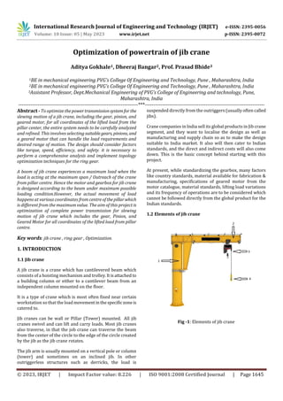
- 1. International Research Journal of Engineering and Technology (IRJET) e-ISSN: 2395-0056 Volume: 10 Issue: 05 | May 2023 www.irjet.net p-ISSN: 2395-0072 © 2023, IRJET | Impact Factor value: 8.226 | ISO 9001:2008 Certified Journal | Page 1645 Optimization of powertrain of jib crane Aditya Gokhale1, Dheeraj Bangar2, Prof. Prasad Bhide3 1BE in mechanical engineering PVG’s College Of Engineering and Technology, Pune , Maharashtra, India 2BE in mechanical engineering PVG’s College Of Engineering and Technology, Pune , Maharashtra, India 3Assistant Professor, Dept.Mechanical Engineering of PVG’s College of Engineering and technology, Pune, Maharashtra, India ---------------------------------------------------------------------***--------------------------------------------------------------------- Abstract - To optimize thepowertransmissionsystemfor the slewing motion of a jib crane, including the gear, pinion, and geared motor, for all coordinates of the lifted load from the pillar center, the entire system needs to be carefully analyzed and refined. This involves selecting suitablegears, pinions, and a geared motor that can handle the load requirements and desired range of motion. The design should consider factors like torque, speed, efficiency, and safety. it is necessary to perform a comprehensive analysis and implement topology optimization techniques for the ring gear. A boom of jib crane experiences a maximum load when the load is acting at the maximum span / Outreach of the crane from pillar centre. Hence the motor and gearbox for jib crane is designed according to the beam under maximum possible loading condition.However, the actual movement of load happens at various coordinates from centreofthepillarwhich is different from the maximum value. The aim of this project is optimization of complete power transmission for slewing motion of jib crane which includes the gear, Pinion, and Geared Motor for all coordinates of the lifted load from pillar centre. Key words: jib crane , ring gear , Optimization. 1. INTRODUCTION 1.1 Jib crane A jib crane is a crane which has cantilevered beam which consists of a hoisting mechanism and trolley.Itisattached to a building column or either to a cantilever beam from an independent column mounted on the floor. It is a type of crane which is most often fixed near certain workstation so that the loadmovementinthespecificzoneis catered to. Jib cranes can be wall or Pillar (Tower) mounted. All jib cranes swivel and can lift and carry loads. Most jib cranes also traverse, in that the job crane can traverse the beam from the center of the circle to the edge of the circle created by the jib as the jib crane rotates. The jib arm is usually mounted on a vertical pole or column (tower) and sometimes on an inclined jib. In other outriggerless structures such as derricks, the load is suspended directly from the outriggers (usually often called jibs). Crane companies in India sell its global products in Jib crane segment, and they want to localise the design as well as manufacturing and supply chain so as to make the design suitable to India market. It also will then cater to Indian standards, and the direct and indirect costs will also come down. This is the basic concept behind starting with this project. At present, while standardizing the gearbox, many factors like country standards, material available for fabrication & manufacturing, specifications of geared motor from the motor catalogue, material standards, lifting load variations and its frequency of operations are to be considered which cannot be followed directly from the global product for the Indian standards. 1.2 Elements of jib crane Fig -1: Elements of jib crane
- 2. International Research Journal of Engineering and Technology (IRJET) e-ISSN: 2395-0056 Volume: 10 Issue: 05 | May 2023 www.irjet.net p-ISSN: 2395-0072 © 2023, IRJET | Impact Factor value: 8.226 | ISO 9001:2008 Certified Journal | Page 1646 Fig -1: Elements of gearbox 1) Pillar: Vertical Member of jib crane which support the complete Jib 2) Jib Arm: Horizontal member on which the Hoist travel. Hoist: Lifting machine which lifts the load. It has 2 motions a ) Lifting/ Lowering , b ) Travelling. 3) Pendant: It is one of the devices which gives control signals to the jib crane, other devices are Radio remote, Joystick etc… 4) Pinion: It engages with the Gear ring which revolves and rotates giving slewing motion to the Jib arm. 5) Gear Ring: The Gear is fixed to pillar and pinion revolve around the gear to give slewing motion to jib arm. 6) Slip Ring assembly: Slip Ring assembly is needed to deliver the power supply to the other machineries as the jib cranes rotates 360 degrees. 7 ) Festoon System: System delivering power to the hoist based C track and power supply trolleys. 1.2 Calculations Fig -2: front view and top view of jib crane Table -1 Terminologies and abbreviations Total cycles- 25000 Jib rpm = 1 Total duration = 25000 min Total duration in h = 4166.67 2. Types of loads acting on jib crane- 1.Uniformly Distributed Load (UDL) (Festoon system) 2.Point Load 3. Live Load 4.Fixed Crane Load Term abbrevia tion Hoist dimensions abbreviation Safe working load(SWL) GL Length- LH Out reach L Width- BH Hook approach _Inner Lan 1 Jib Slewing rpm- n Hook approach _Outer Lan 2 Safe Working Load (SWL) dimensions- Beam Overhang on rear side L1 Length L swl Position of Arm L2 Width B swl Arm Height H1 Height H swl Diameter of Pillar Ds Height H swl Hook path above floor H Hoist Head Room C Floor to bottom of beam Ho = H+C Hoist weight Gh
- 3. International Research Journal of Engineering and Technology (IRJET) e-ISSN: 2395-0056 Volume: 10 Issue: 05 | May 2023 www.irjet.net p-ISSN: 2395-0072 © 2023, IRJET | Impact Factor value: 8.226 | ISO 9001:2008 Certified Journal | Page 1647 2.1.Calculations for UDL (festoon system) - Fig -3: MOI explaination UDL= length of UDL = Width of UDL = b m ∴Point load= Horizontal distance of CG of udl =x Vertical distance of CG of udl =y Distance of CG of UDL from pillar Ic = MMI of UDL around CG = Io = Moment about pillar = 2.2 Calculations for point load & fixed crane loads- Load = m kg ∴Total load = M = m * Mass factor Length of load = a m Width of load = b m Diatance of x coordinate = x Distance of y coordinate = y ∴Radius = ∴ Ic = Io = Ic + Moment around pillar = 2.3 Calculations for live load Iteration 1- Total load = M = SWL + Hoist load Radius = R1 m Ic swl = Ic hoist = ∴Io1= ∴Moment around pillar =M1 = Iteration 2- R2 ∴Corresponding Io2= Ic swl + Ic hoist + ∴Moment around pillar =M2 = Iteration 3- R3 ∴Corresponding Io3 = Ic swl + Ic hoist + ∴Moment around pillar =M3 = And so on for further iterations ∴Max. Io = ∴RMS Io = Max. Moment = ∴RMS moment =
- 4. International Research Journal of Engineering and Technology (IRJET) e-ISSN: 2395-0056 Volume: 10 Issue: 05 | May 2023 www.irjet.net p-ISSN: 2395-0072 © 2023, IRJET | Impact Factor value: 8.226 | ISO 9001:2008 Certified Journal | Page 1648 ∴Total MMI = ∴Total axial force = ∴Total Moment around pillar = Arm height = H1 m ∴ Radial force = Total acceleration torque= Frictional force = ∴ Frictional torque = Axial torque= ∴Total torque = Frictional torque + axial torque + acceleration torque Nm Set motor rpm = Total ratio = ∴ ∴power = Total efficiency = ∴ Final motor power = kW Optimization of power of motor Table -2: Input constants – Hook approach _Inner Lan 1 750 mm Hook approach _Outer Lan 2 250 mm Beam Overhang on rear side L1 350 mm Position of Arm L2 600 mm Arm Height H1 1030 mm Diameter of Pillar Ds 670 mm Hook path above floor H 3000 mm Hoist Head Room C 300 mm Floor to bottom of beam Ho=H+C 3300 mm Hoist weight Gh 600 kg Hoist dimensions- Length LH 350 mm Width- BH 350 mm Jib Slewing rpm- 1 Safe Working Load (SWL) dimensions- Length L swl 1581 mm Width B swl 255 mm Height H swl 1581 mm UDL (Uniformly Distributed Load) - Festoon 1 UDL=5 kg/m Width of UDL= 50 mm= 0.05 m= b UDL start(Y start)= 200 mm UDL end(Y end)= 6000 mm Total Y= = 6000-200 =5800 mm = 5.8 m = a CG of Y= = 3100 mm = Y coordinate Distance of festoon 1 from jib arm = 500 mm = X coordinate 2. HEADING 2 Using maximum method-
- 5. International Research Journal of Engineering and Technology (IRJET) e-ISSN: 2395-0056 Volume: 10 Issue: 05 | May 2023 www.irjet.net p-ISSN: 2395-0072 © 2023, IRJET | Impact Factor value: 8.226 | ISO 9001:2008 Certified Journal | Page 1649 (x,y)=(500,3100) ∴Radius= = 3140.1 mm R = 3.14 m ∴Total load = = = = 29 kg Mass factor(M.F.) = 1.1 ∴Load with M.F = ∴M =31.9 kg ∴MR^2= = 314.5 kgm^2 ∴Self MR^2= Ic =MMI about CG of festoon1 = Ic =89.4 kgm^2 ∴MMI about pillar= = 89.4+ 314.5 = 404 kgm^2 ∴Moment about Pillar = =970.1 Nm Festoon 2- For festoon 2, Distance of festoon 1 from jib arm = 750 mm = X coordinate (x,y) = (750,3100) ∴Radius= 3189.4 mm M =31.9 kg ∴MR^2= 31.9* 3.189^2 = 324.5 kgm^2 ∴Self MR^2 =Ic= MMI about CG of festoon2 = =89.4 kgm^2 ∴MMI about pillar = Io = 413.9 kgm^2 ∴Moment about Pillar = = 970.1 Nm Table -3 Point loads Name of Load Point load1 Point load2 Point load 3 Discription Electric cubical Canopy Drives Load ‘L’ (kg) 500 0 57 Length a’(mm) 500 1000 250 Width’b’(mm) 250 500 250 X coordinate (mm) 750 0 500 Y coordinate (mm) 500 0 0 Radius ’R’ (mm) 901.4 0 500 Mass factor (MF) 1 1 1 Load with M.F.’M’(kg) ( 500 0 57 Σload=557 kg
- 6. International Research Journal of Engineering and Technology (IRJET) e-ISSN: 2395-0056 Volume: 10 Issue: 05 | May 2023 www.irjet.net p-ISSN: 2395-0072 © 2023, IRJET | Impact Factor value: 8.226 | ISO 9001:2008 Certified Journal | Page 1650 406.3 0 14.3 Self MR^2 ’Ic’ 13 0 0.6 Total Mr^2 ’Io’ ( 419.3 0 14.8 Moment (Nm) 2452.5 0 0 Table -4 Fixed crane load Name of Loads Point load 1 Point load 2 Discriptions Jib Arm Load’L’(kg) 785 150 Length(a) L+Lan2+L1 6600 400 Width(b) 250 250 X coordinate 0 0 Y coordinate (L+Lan2+L1)/2-L1 = 2950 L2= 600 Radius (mm) 2950 600 Mass Factor ‘MF’ 1.3 1.3 Load with MF ‘M’(kg) ( 1020.5 195 MR^2 8880.9 70.2 Self MR^2 3709.7 3.6 Total Mr^2 Io =( ) 12590.6 73.8 Moment (Nm) 29532.75 1147.7
- 7. International Research Journal of Engineering and Technology (IRJET) e-ISSN: 2395-0056 Volume: 10 Issue: 05 | May 2023 www.irjet.net p-ISSN: 2395-0072 © 2023, IRJET | Impact Factor value: 8.226 | ISO 9001:2008 Certified Journal | Page 1651 Live load- Iteration 1 Max. outreach= 6000 mm Max. Load = 5000 kg Hoist load = 600 kg ∴Total load= 5600 kg Iteration1- SWL=5000 kg Hoist Load= 6000 kg Total Load= SWL + Hoist load M = 5600 kg Distance of SWL & Hoist load from pillar= Max. of outreach/2 & position of arm =max =max = 3000 mm = R1 ∴ MR^2= = = 50400 kgm^2 ∴Self MR^2 of SWL= Ic1= = =1068.58 kgm^2 ∴ Self MR^2 of hoist= Lc2= = =12.25 kgm^2 ∴Total MR^2 around the pillar = Io = MR^2 + Ic1 + Ic2 =50400 + 1068.58 + 12.25 = 51480.8 kgm^2 Moment around jib arm = = =164808 Nm Iteration 2- Self MR^2 of SWL= Ic1 =1068.58 kgm^2 ∴ Self MR^2 of hoist= Lc2 = 12.25 kgm^2 R2 = = 3750 mm = 3.75 m ∴ MR^2 = = 78750 kgm^2 ∴ Total MR^2 = MR^2 + Ic1 + Ic2 = 78750 + 1068.58 + 12.25 = 79830.8 kgm^2 ∴ Moment = = 206010 Nm Iteration3- Self MR^2 of SWL= Ic1 =1068.58 kgm^2 ∴Self MR^2 of hoist= Lc2 = 12.25 kgm^2 R3 = = 4500 mm = 4.5 m ∴MR^2 = = 113400 kgm^2 ∴Total MR^2 = MR^2 + Ic1 + Ic2 = 113400 + 1068.58 + 12.25 = 114480.8 kgm^2 ∴Moment = = = 247212 Nm Iteration 4- Self MR^2 of SWL= Ic1 =1068.58 kgm^2 ∴Self MR^2 of hoist= Lc2
- 8. International Research Journal of Engineering and Technology (IRJET) e-ISSN: 2395-0056 Volume: 10 Issue: 05 | May 2023 www.irjet.net p-ISSN: 2395-0072 © 2023, IRJET | Impact Factor value: 8.226 | ISO 9001:2008 Certified Journal | Page 1652 = 12.25 kgm^2 R4 = = 5250 mm = 5.25 m ∴MR^2 = = 154350 kgm^2 ∴Total MR^2 = MR^2 + Ic1 + Ic2 = 154350 + 1068.58 + 12.25 = 155430 kgm^2 ∴Moment = = 288414 Nm Iteration 5- Self MR^2 of SWL= Ic1 =1068.58 kgm^2 ∴Self MR^2 of hoist= Lc2 = 12.25 kgm^2 R5 = = 6000 mm = 6 m ∴MR^2 = = 201600 kgm^2 ∴Total MR^2 = MR^2 + Ic1 + Ic2 = 201600 + 1068.58 + 12.25 = 202680 kgm^2 ∴Moment = 329616 Nm Table -5 MMI and moment using maximum and RMS method MMI around the pillar of total load Square Moment around the pillar (Nm) Square Iterat ion1 51480.8 000000 265027560 0.08476 164808.00 0000000 27161676 864 Iterat ion2 79830.8 637296101 9.33476 206010 42440120 100 Iterat ion3 114480. 8 131058598 65.08480 247212 61113772 944 Iterat ion4 155430. 8 241587421 37.33480 288414 83182635 396 Iterat ion5 202680. 8 410795178 36.08480 329616 10864670 7456 Max. MMI = 202680. 8 RMS MMI = 132187.3 Max. Moment = 329616 Nm RMS Moment= 253986 Nm
- 9. International Research Journal of Engineering and Technology (IRJET) e-ISSN: 2395-0056 Volume: 10 Issue: 05 | May 2023 www.irjet.net p-ISSN: 2395-0072 © 2023, IRJET | Impact Factor value: 8.226 | ISO 9001:2008 Certified Journal | Page 1653 Table - 6 RMS power calculated using different iterations Safe Working Load(SWL)(kg) Outreach(m) Hoist load(kg) Max. MMI RMS MMI Max. moment Nm RMS Moment Nm 5000 6 600 202680 132187 329616 253986 1000 6 600 57826 37692 94176 75267 2000 6 600 94039 61315 153036 117922 3000 6 600 13053.4 84939 211896 163276 Table – 7 Power calculated using maximum method Load (kg) 2 2.5 3 3.5 4 4.5 5 5.5 6 500 0.029 0.037 0.046 0.056 0.066 0.078 0.090 0.103 0.116 1000 0.037 0.048 0.059 0.072 0.086 0.101 0.118 0.135 0.153 1500 0.045 0.058 0.073 0.089 0.106 0.125 0.146 0.167 0.19 2000 0.053 0.069 0.086 0.106 0.127 0.149 0.174 0.199 0.227 2500 0.061 0.079 0.1 0.122 0.147 0.173 0.201 0.232 0.264 3000 0.069 0.090 0.113 0.139 0.167 0.197 0.229 0.264 0.301 3500 0.076 0.1 0.127 0.156 0.187 0.221 0.257 0.296 0.338 4000 0.084 0.111 0.140 0.172 0.207 0.245 0.285 0.329 0.375 4500 0.092 0.121 0.154 0.189 0.227 0.269 0.313 0.361 0.411 5000 0.1 0.132 0.167 0.205 0.247 0.293 0.341 0.39S3 0.4478 Table – 8 Comparison with power calculated using RMS method Load (kg) 2 2.5 3 3.5 4 4.5 5 5.5 6 500 0.025 0.031 0.038 0.046 0.054 0.063 0.072 0.082 0.093 1000 0.030 0.039 0.048 0.058 0.068 0.080 0.092 0.105 0.119 1500 0.036 0.046 0.058 0.07 0.083 0.097 0.112 0.128 0.145 2000 0.042 0.054 0.067 0.082 0.097 0.114 0.032 0.150 0.171 2500 0.048 0.062 0.077 0.094 0.112 0.131 0.151 0.173 0.197 3000 0.054 0.07 0.087 0.106 0.126 0.148 0.171 0.196 0.223 3500 0.06 0.077 0.097 0.118 0.14 0.165 0.191 0.219 0.249 4000 0.065 0.085 0.106 0.13 0.155 0.182 0.211 0.242 0.0275 4500 0.071 0.093 0.116 0.733 0.169 0.199 0.231 0.265 0.301 5000 0.077 0.1 0.126 0.154 0.184 0.216 0.251 0.288 0.32 Outreach (m) Similarly we can find Max. and RMS Io and MMI & compare togrther
- 10. International Research Journal of Engineering and Technology (IRJET) e-ISSN: 2395-0056 Volume: 10 Issue: 05 | May 2023 www.irjet.net p-ISSN: 2395-0072 © 2023, IRJET | Impact Factor value: 8.226 | ISO 9001:2008 Certified Journal | Page 1654 % Decrease in power for maximum Load & outreach conditions- % Decrease in power (kW)= Conclusion- For each iteration of load vs outreach data, Root Mean Square method power is coming to be minimum for corresponding iteration for maximum method. Thus, power required to rotate the jib is reduced by 28.41% Validation using Tooth root stress - Known data – Module = m= 6 Pressure angle = 20 deg Helix angle = 0 deg Pinion gear = gear 1 Ring gear = gear 2 ∴ V1 Tangential force transmitted = Wt1 Velocity factor Kv1 Permissible stress BHN Infinite life strength for tooth root stress Syt Factor of safety = ∴ Balanced FOS ∴ Transmittable power = ∴Calculation accuracy Validation using flank strength - Contact strength = Sc = CL =Life Factor CH= Hardness factor CT =Temperature Factor CR = Reliability Factor AGMA stress ratio = ∴Dynamic factor = Kv1 = ∴Safety factor = ∴Geometrical factor = ∴Weight force transmitted = Wtf= ∴Safety factor = ∴ Transmittable power = ∴ Calculation accuracy
- 11. International Research Journal of Engineering and Technology (IRJET) e-ISSN: 2395-0056 Volume: 10 Issue: 05 | May 2023 www.irjet.net p-ISSN: 2395-0072 © 2023, IRJET | Impact Factor value: 8.226 | ISO 9001:2008 Certified Journal | Page 1655 3. CONCLUSIONS The accuracy coming from method of tooth root stress is around 85% for gear 1(pinion) while for some gear of is of 115% While using flank strength method the accuracy for gear 1 is coming to be 81% and for gear 2 it is around 150%. In general validation unsungtoothrootstressisconsiderable and can be used for optimization of ring gear. REFERENCES [1] Krunal Gandhare,VinayThute,“Design OptimizationofJib Crane Boom Using Evolutionary Algorithm”, International Journal of Scientific Engineering and Research, Volume 3 Issue 4, pp. 2-8, 2014. [2] Baker J. Cranes in Need of Change, Engineering, Vol. 211, PP- 298, 1971. [3] Sandip D. Shinde“Standardization of Jib Crane Design by “F.E.M. Rules” and Parametric Modeling”, International Journal of Recent Trends in Engineering, Vol. 1, No. 5, pp. 145-149, May 2009. [4] K. Suresh Bollimpelli, V. Ravi Kumar, “Design and Analysis of Column Mounted JIB Crane”, International Journal of Research in Aeronautical and Mechanical Engineering, Vol 3 issue 1, pp. 32-52, 2015. [5] Amreeta R. K. “Design and StressAnalysisofSingleGirder Jib Crane”, International Journal of Engineering Research & Technology Vol. 4 Issue 09, pp. 932-936, September-2015. [6] Subhash N. Khetre,S.P. Chaphalkar“ModellingandStress Analysis of Column Bracket For Rotary Jib Crane”, international journal of mechanical engineering and technology Volume 5, Issue 11, pp. 130-139, November 2014. [7] Gerdemeli .I, Kurt .S and Tasdemir “Design and Analysis with Finite Element Method of Jib Crane”, Mechanical Engineering Istanbul Technical University – Turkey 2012. [8] B. Ünal, I. Gerdemeli, C. E. Imrak “Modelling and Static Stress Analysis of Shipyard Jib Crane With Finite Element Method”, University Review Vol. 2, No. 4 Trenčín: Alexander Dubček University of Trenčín2, 90 p, 2008. [9] Fuad Hadžikadunić, NedeljkoVukojević and SenadHuseinović “An Analysis of Jib Crane Constructive Solution in Exploatation”, 12th International Research/Expert Conference Trends in the Development of Machinery and Associated Technology'' TMT2008,Istanbul, Turkey, pp. 26–30 August, 2008 10) Shigley's Mechanical EngineeringDesign Book byJ.Keith Nisbeth and Richard G. Budyna BIOGRAPHIES Aditya Anant Gokhale is currently pursuing Bachelor of Engineering degree in mechanical engineering program in Pune Vidhyarthi Griha's College of Engineering and Technology. Dheeraj Bharat. Bangar is currently pursuing Bachelor of Engineering degree in mechanical engineering program in Pune Vidhyarthi Griha's College of Engineering and Technology. Prof. Bhide Prasad Pramod Assistant Professor3 Assistant Professor, Dept . Mechanical Engineering of PVG’s College of Engineering and technology, Pune, Maharashtra, India