Improving Gas Turbine – HRSG output using Inlet Air Chilling and Converted Evaporator
•
0 likes•41 views

https://irjet.net/archives/V4/i11/IRJET-V4I1172.pdf
![International Research Journal of Engineering and Technology (IRJET) e-ISSN: 2395-0056
Volume: 04 Issue: 11 | Nov -2017 www.irjet.net p-ISSN: 2395-0072
© 2017, IRJET | Impact Factor value: 6.171 | ISO 9001:2008 Certified Journal | Page 429
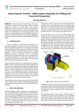
Fig-2: Velocity drop
Fig-3: Velocity distribution
The analysis showed total pressure drop values,whichwere
quite low compared to previous model. In the proposed
model the pressure drop was expected to be around 1.97”
WC From rain hood to the Gas Turbine inlet.
There also was significant reductionintheductflowinduced
vibration due to effective diffusion of stratified high velocity
air entering compressor inlet plenum. It was confirmed by
having a condition monitoring team check the vibrations.
Flow Rate 130 Kg/S @ 20oC
Pre filter 0.3”WC
Water coil 0.50”WC
Final filter 0.35”WC
Pressure drop:
Ambient – Filters 1.22”WC
Filters – Inlet plenum 0.75”WC
Total pressure drop 1.97”WC
2.1 Importance of compressor bellmouth
differential pressure.
The static pressure difference between the inside of the
bellmouth and static ambient pressure will give an
indication of mass flow as total pressure will remain the
same, the static drop converts into dynamic component
(Velocity) along with flow area will give mass flow of less
dense inlet air.
Mass flow = Speed * Density * Area
Pitot tube is significant in determining the inlet air flow
which was vital to see the changeinflowcharacteristicsafter
inlet air chilling. When the Pitot tube is connected to a
manometer, the resultant displacementoffluidismeasureof
the “Velocity Pressure”.
Velocity Pressure= P1-P2 = ½*ρ*v2,
ρ=density of air
V = sqrt 2(P1-P2) / ρ
But P1-P2 = ρw * g * H,
ρw = Density of water in manometer is 1000kg/m3
H= Height of water column in meters
g=9.81 m/s2
V = sqrt 2* ρw * H * g / ρ
= sqrt 2* 1000 * H * 9.81 / ρ
H =height of liquid column to be expressedinmmofwater hv
H = hv / 1000
V = sqrt 2* 1000 *hv /1000*9.81/ρ m/sec
So, Velocity air flow = 4.43 sqrt hv/ρ m/sec
In practice the density of air is affected by temperature and
by static pressure and so it is necessary to know the air
density at some reference temperature and pressure, and
then by applying corrections the value of test conditions are
obtained. The density of air at 1.013 bar 0deg is 1.29 kg/m3
and it varies inversely to the absolute temperature and
directly to absolute pressure.
The density ρfor any temperature and pressure condition is
thus given by
ρ = 1.29*[273/T]*(10363+hs/10363)*B/760
Where, 1.29 is density of air at 0degC and at 10.13 bar in
kg/m3
T is air temperature, K
hs is static pressure in duct in mmWC
B is barometric pressure in mmHg
10363 is standard pressure in mmWC](data:image/gif;base64,R0lGODlhAQABAIAAAAAAAP///yH5BAEAAAAALAAAAAABAAEAAAIBRAA7)
Recommended
Recommended
More Related Content
What's hot
What's hot (20)
Similar to Improving Gas Turbine – HRSG output using Inlet Air Chilling and Converted Evaporator
Similar to Improving Gas Turbine – HRSG output using Inlet Air Chilling and Converted Evaporator (20)
More from IRJET Journal
More from IRJET Journal (20)
Recently uploaded
Recently uploaded (20)
Improving Gas Turbine – HRSG output using Inlet Air Chilling and Converted Evaporator
- 1. International Research Journal of Engineering and Technology (IRJET) e-ISSN: 2395-0056 Volume: 04 Issue: 11 | Nov -2017 www.irjet.net p-ISSN: 2395-0072 © 2017, IRJET | Impact Factor value: 6.171 | ISO 9001:2008 Certified Journal | Page 428 Improving Gas Turbine – HRSG output using Inlet Air Chilling and Converted Evaporator Utkarsh Adhyaru ---------------------------------------------------------------------***--------------------------------------------------------------------- Abstract - Every machine ever created has some output limitations with respect to the inputsgiventothem. Inorder to change the output rate some design and condition modifications have to be done in order to get effectiveness beyond the designed parameters and at thesametimealsonot hamper the metallurgical and operational stability of the machine. In order to get more out of a GT-HRSG, sincetheyare temperature controlled machines, some design modifications proved a considerable increaseinoutputkeepingthe efficiency at bay. 1. INTRODUCTION With a continuous improvement and expansion in process plants going on, there is a vital need of utilities to have more efficiency to put in more effort to give the intend output and keep production at par. Gas turbineswork on the principle of hot gas expanding. They have a fixed loading capacity. In order to increase the loading, the ambient temperature plays an important role as it eventually determines the output temperature. In case of peak load, if the exhaust temperature reaches the critical value, the machine will not allow any more power loading and the machine will go into temperature control. Another problem related to over temperature is related to HRSG. In order to increase the steam loading of HRSG there is a provision of supplementary firing. Incaseofelevated gas turbine exhausted temperature, added with supplementary firing the metal temperature of superheater-II tends to increase as the supplementary firing is followed by the superheater-II. The idea of improvingtheconditionsofthese machines at peak load was to improve the reference temperatures of turbine and at the same time improve the metallurgy in order to keep the HRSG healthy. The modifications thus done was done in a GE Frame 6B Gas Turbine with a power capacity of 34.5MW. Along with this another design change was done in the 120 MT HRSG which followed. 2. INLET AIR CHILLING The Frame 6B has a capacity of goinguptoa loadingcapacity of around 34 MW which was observed on cold winter days where the ambient temperature was less and the reference exhaust temperature (TTXM) allowed the machine to go as much as 34-34.5 MW on preselect mode, before it can go to temperature control. On summer days this can come down to as low as 29 MW and the machine is almost on the verge of accepting no more MW input. The turbines used in this case had very high demanding complex loads and importing power was proving very expensive. To avoid this the idea of Inlet Air Chilling (IAC) was tried to see if this can prove out to be beneficial. The idea was to cool the incoming air so as to get more window for MW input and run the machine on maximum loads. To put the idea in use, a new set of filter module was installed. It had air inlet from three sides. The fourth side was attached to a bellmouth which then ended in the inlet plenum. The filter module had chilled water tubes running throughout. The filters were placed in an order so has to have the best possible air in inlet. It had one mesh to avoid any big particle enter. Then it had a primary filter followed by chilled water tubes, and then a denser secondary filter. A 1000 TR vacuum absorption cycle based chiller was commissioned and it could sufficeforanyclimateconditions. Fig-1: Solid model of Inlet air bellmouth This filter assembly not only providedanoptiontohaveinlet air chilling but also provide uniform air flow throughout the three filter modules. The CFD analysis iterations provided a final design to achieve optimum airflow with minimum backpressure. The following figures clearly shows uniform entry of streamlines to the aero-acoustic diffusers at 3D modeling and top view of CFD results respectively, which reduce the vortex and turbulence with in the Gas Turbine inlet duct. This would also reduce flow induced vibration in the duct.
- 2. International Research Journal of Engineering and Technology (IRJET) e-ISSN: 2395-0056 Volume: 04 Issue: 11 | Nov -2017 www.irjet.net p-ISSN: 2395-0072 © 2017, IRJET | Impact Factor value: 6.171 | ISO 9001:2008 Certified Journal | Page 429 Fig-2: Velocity drop Fig-3: Velocity distribution The analysis showed total pressure drop values,whichwere quite low compared to previous model. In the proposed model the pressure drop was expected to be around 1.97” WC From rain hood to the Gas Turbine inlet. There also was significant reductionintheductflowinduced vibration due to effective diffusion of stratified high velocity air entering compressor inlet plenum. It was confirmed by having a condition monitoring team check the vibrations. Flow Rate 130 Kg/S @ 20oC Pre filter 0.3”WC Water coil 0.50”WC Final filter 0.35”WC Pressure drop: Ambient – Filters 1.22”WC Filters – Inlet plenum 0.75”WC Total pressure drop 1.97”WC 2.1 Importance of compressor bellmouth differential pressure. The static pressure difference between the inside of the bellmouth and static ambient pressure will give an indication of mass flow as total pressure will remain the same, the static drop converts into dynamic component (Velocity) along with flow area will give mass flow of less dense inlet air. Mass flow = Speed * Density * Area Pitot tube is significant in determining the inlet air flow which was vital to see the changeinflowcharacteristicsafter inlet air chilling. When the Pitot tube is connected to a manometer, the resultant displacementoffluidismeasureof the “Velocity Pressure”. Velocity Pressure= P1-P2 = ½*ρ*v2, ρ=density of air V = sqrt 2(P1-P2) / ρ But P1-P2 = ρw * g * H, ρw = Density of water in manometer is 1000kg/m3 H= Height of water column in meters g=9.81 m/s2 V = sqrt 2* ρw * H * g / ρ = sqrt 2* 1000 * H * 9.81 / ρ H =height of liquid column to be expressedinmmofwater hv H = hv / 1000 V = sqrt 2* 1000 *hv /1000*9.81/ρ m/sec So, Velocity air flow = 4.43 sqrt hv/ρ m/sec In practice the density of air is affected by temperature and by static pressure and so it is necessary to know the air density at some reference temperature and pressure, and then by applying corrections the value of test conditions are obtained. The density of air at 1.013 bar 0deg is 1.29 kg/m3 and it varies inversely to the absolute temperature and directly to absolute pressure. The density ρfor any temperature and pressure condition is thus given by ρ = 1.29*[273/T]*(10363+hs/10363)*B/760 Where, 1.29 is density of air at 0degC and at 10.13 bar in kg/m3 T is air temperature, K hs is static pressure in duct in mmWC B is barometric pressure in mmHg 10363 is standard pressure in mmWC
- 3. International Research Journal of Engineering and Technology (IRJET) e-ISSN: 2395-0056 Volume: 04 Issue: 11 | Nov -2017 www.irjet.net p-ISSN: 2395-0072 © 2017, IRJET | Impact Factor value: 6.171 | ISO 9001:2008 Certified Journal | Page 430 So using this the condition monitoring was done with and without chilling and mass flow was thus calculated. Gas turbine inlet mass flow without chilling: Temperature of air inside the duct = 34 degC Static pressure of air as per Pitot tube measurement = 18.2 (-) mmWC Barometric pressure = 760 mmHg Velocity at Elbow exit (from velocitydistributionasperCFD) = 22.5 m/Sec Cross sectional area of duct at Elbow = 4.61 m2 Volume flow = 103.7 m3/sec Air density = 1.1451 kg/m3 at duct conditions Thus, Mass flow = 118.74 Kg/Sec Gas turbine inlet mass flow with chilling: Temperature of air inside the duct = 21 degC Static pressure of air as per Pitot tube measurement = 32.92 (-) mmWC Barometric pressure = 760 mmHg Velocity at Elbow exit (from velocitydistributionasperCFD) = 22.5 m/Sec Cross sectional area of duct at Elbow = 4.61 m2 Volume flow = 103.7 m3/sec Air density = 1.1941 kg/m3 at duct conditions Thus, Mass flow = 123.82 Kg/Sec The above calculations were done against the base load design mass flow of 135 Kg/Sec. The calculations clearly indicate a higher density of air flowing after using the inlet air chilling. In case of any sweating, a condensate collection pan is provided leaving air side of each dehumidifyingpan.It also had a condensate trap of at least 2.5 times the expected negative static pressure of the unit. Fig-4: Coil sweating recovery U-tube Expected negative pressure is 0.1+.05+.09=1.5” WC d= 1.5” WC * 2.5 = 3.75” Trap used was of 4” (100mm). The following graph shows how the gas turbine behaves without any inlet air chilling in normal conditions. Table-1: Gas turbine data without chilling GT DATA WITHOUT INLET AIR CHILLING Parameter Unit 1200 1300 1400 1600 Speed RPM 5020 5062 5057 5030 Load MW 26.5 26.8 26.2 25.5 GT speed % 98.55 99.37 99.29 98.75 Flow divider speed % 68.42 68.59 67.7 66.2 FSR % 69.16 69.04 68.38 67.54 Liq fuel flow kg/sec 2.6 2.67 2.65 2.59 Mass fuel flow TPH 8.13 8.19 8.03 8.02 Compressor inlet temp. degC 30 32 34 33 Inlet air filter D.P INWC 1.37 1.39 1.97 1.3 Compressor outlet pressure Bar 8.7 8.79 8.67 8.52 I.G.V. Angle DGA 83.9 83.9 83.9 83.8 Exhaust Temperature degC 573 574 575 576 Spread Limit degC 69.4 69.4 69.4 69.4 HRSG flue gas inlet pressure MMWC 274 276.7 273 262 Compressor discharge temperature degC 366 371 373 372 Heat rate (open cycle) 3169 3169 3169 Steam/fuel ratio 19.67 20.01 18.23 Time The following graph shows how the gas turbine behaves with inlet air chilling in normal conditions. Table-2: Gas turbine data with chilling GT DATA WITH INLET AIR CHILLING Parameter Unit 1200 1300 1400 1600 Speed RPM 5018 5047 5030 5010 Load MW 26 26 26 26 GT speed % 98.5 99.09 98.75 98.35 Flow divider speed % 65.12 65.53 65.2 65.53 FSR % 66.45 65.79 66.6 67.11 Liq fuel flow kg/sec 2.56 2.56 2.57 2.57 Mass fuel flow TPH 7.93 7.89 7.9 7.91 Compressor inlet temp. degC 19 20 19 19 Inlet air filter D.P INWC 1.52 1.54 1.51 1.47 Compressor outlet pressure Bar 8.97 9.04 9 8.93 I.G.V. Angle DGA 83.7 83.7 83.7 83.7 Exhaust Temperature degC 526 522 524 526 Spread Limit degC 172.7 176.6 176.7 177 HRSG flue gas inlet pressure MMWC 297 298.6 299.6 296 Compressor discharge temperaturedegC 351 353 351 350 Heat rate (open cycle) 3169 3169 3169 Steam/fuel ratio 17.7 19.18 18.22 Time Based on the observations taken at different time of the day, it was observed that the inlet air chilling does a considerable amount of change in the machine. InitiallyitreducestheFSR,
- 4. International Research Journal of Engineering and Technology (IRJET) e-ISSN: 2395-0056 Volume: 04 Issue: 11 | Nov -2017 www.irjet.net p-ISSN: 2395-0072 © 2017, IRJET | Impact Factor value: 6.171 | ISO 9001:2008 Certified Journal | Page 431 which in turns also improves the fuel going inside the GT. According to the observations both noted with the flow meter and mass flow with micro motion,it wasobservedthat less fuel goes inside the machine thus reducing the flow divider speeds. With low inlet temperature the compressor outlet pressure is high with low exhaust temperatures, low compressor discharge temperatures and high HRSG flue gas pressures. Thus allowing more temperature window to increase the capacity of the machine without going into temperature control. The only downside observed with IAC is the increase in suction air filter D.P. which has to be monitored during operations. Also at the end of HRSG NOx and Sox have to be monitored to avoid self-condensing that might result in damaging of HRSG tubes. On longer runs and more report gathering it was observed that the heat rate of the turbine also improved. Also additionally the steam generation of HRSGimproved.Alsoat the end of HRSG the temperature was high so an additional LP evaporator was installed which couldgivea steamoutput of 6barg which was used to run the 1000 TR chiller so the entire energy was conserved quite efficiently. Table-3: Data comparison WithChilling Day 1 Time Fuel Totalizer Power totalizer Totalpower generater Fuel consume Open cycle MW 12:15 131987 402703 80 26 3013 29 15:00 132013 402783 120 39 3013 30 19:00 132052 402903 98 32 3027 28 22:00 132084 403001 46 14 2821 31 0:00 132098 403047 197 58 3004 30 6:00 132156 403226 523 169 2995 30 Day 2 132372 403878 227 74 3022 30 Day 3 132467 404171 293 95 3006 29 Withoutchilling Day 4 685.6 223.8 3026 29 Day 5 682.6 218.9 2973 28 Day 6 670.5 220.8 3053 28 Total 2038.7 663.5 3017 29 3. CONVERTED EVAPORATOR With higher gas turbine loads and more output required out of HRSG, supplementary firing is required tocompensatefor minor heat loss and add up to the heat input to further increase the steam flow and also compensated for any process abnormalities to keep the header pressureconstant. With all the modifications thus made, there was a constant problem of tube failures in HRSG at certain point of time. It was observed that the super heater-II which was most exposed to the supplementary heat, was exposed to the maximum damage and failed eventually. To avoid this some modification was done in the evaporator. The HRSG used in line with the mentioned gas turbine had a design capacity of 100 TPH capacity of steam generation at 100 barg 495oC. It consist of twoeconomizers,an evaporator module and three super heater module. TheentireHRSG ran on gas turbines outlet flue gas. To compensate or any minor heat loss or process steam requirement change, it had six burners in between super heater II and III. At peak plant loads all the burners were used with full GT load to give maximum steam output. The problem faced had a lot of effect on machine life and also demanded big shutdowns creating a problem for process requirements. To avoid this problem, the initial two modules of superheater II were modified. They were cut and replaced with the same tubes as used in evaporator. It also had coper fins attached to it for maximum heat transferandabsorption in case of supplementary firing and the tubes ran water unlike other superheater tubes which ran steam. This created a jacket for the superheater II section and absorbed the conductive heat coming from the burner flame so as to not damage the superheater tubes. Fig-5: Converted Evaporator in a Heat recovery steam generator Before the change, at peak loads the temperature of superheater II used to go over 515 degC. After the project,
- 5. International Research Journal of Engineering and Technology (IRJET) e-ISSN: 2395-0056 Volume: 04 Issue: 11 | Nov -2017 www.irjet.net p-ISSN: 2395-0072 © 2017, IRJET | Impact Factor value: 6.171 | ISO 9001:2008 Certified Journal | Page 432 the temperature remained below 478 degC. Another benefit was that the flow output of HRSG improved ant increased to 125 TPH from 105 TPH. Additionally there was quite a bit of hunting seen in HRSG when put on flow control which also improved when kept in three element control. The gas turbine used for the particular HRSG is a black start machine and so it’s total time to reach FSNL is about 11 minutes. So the heating of HRSG can be done parallel to the startup or after it reached certain temperature. Both the cases referred to as cold start and hot start. The new tube bundle integrity was to be checked with both startups so as to confirm if it can withstand thermal shocks in case of hot startups. It was observed that a temperature difference persisted between old evaporator and the converted evaporator. But it did not affect the metal temperature of the main superheater II tubes and served the purpose of jacketing the tube module from flame heat. Chart-6: Fatigue effect on modification The study showed that the maximum fatigue effect transpired in the piping at the bottom header of the evaporator, in specific, the feeders that linked the manifold to the lower headers. It was also observed that the tube bundle metal temperature was on the higher side in the transient condition during critical time period of hotstartup phase compared to cold startup and operation. The fatigue analysis results approve that the system is adequate to support the thermal growth without yielding excessive fatigue stresses. Chart-7: Effect on tube life As the graph suggests there is a higher life consumptionrate in the life of tubes, especially that of the converted evaporator as the temperature in that zone is highest for water tubes of 135 barg pressure and so it was to beavoided to take the HRSG in line with hot start procedure and was to be done only in extreme cases as required. 4. CONCLUSION The entire project was to developanincreaseinproductivity in case of a gas turbine – HRSG closed cycle operation and not only did it help to increase the throughput of the machines without affecting the reliability but also made failure intensity less. Table-4: Benefits after modification Gas turbine IAC benefit Description UOM Present With IAC GT output at ISO MW 37.52 37.52 O/C heat rate at ISO kcal/kwh 2764 2764 Ambient temperature degC 35 20 Frequency Hz 50 50 Inlet pressure drop mmWC 100 100 Outlet pressure drop mmWC 225 225 Correction factor for degradation/aging % 5 5 Correction Factors: Temperature CF 1.0350 1.0080 Frequency CF 1.0050 1.0050 Inlet pressure drop CF 1.0000 1.0000 Outlet pressure drop CF 1.0063 1.0063 Part load CF 1.0470 1.0470 Degradation CF 1.0500 1.0500 GT heat rate for conditions kcal/kwh 3166 3083 Values
- 6. International Research Journal of Engineering and Technology (IRJET) e-ISSN: 2395-0056 Volume: 04 Issue: 11 | Nov -2017 www.irjet.net p-ISSN: 2395-0072 © 2017, IRJET | Impact Factor value: 6.171 | ISO 9001:2008 Certified Journal | Page 433 The overall heat rate reduction was of about 83 kcal/kwh. It also improved the loading capacity of GT in hot conditions and avoided the machine to go into temperature control. The bellmouth design proved a huge reduction in pressure drops and uniform velocity throughout the filters. Fig-8: Pressure loss Inlet plenum loss was calculated at two points. One in the filter house and another before the compressor inlet. Atfirst point, a loss of 85-95 mmWC was observed and at point two, a loss of 210 mmWC was observed. According to the gas turbine vendor, a guaranteed inlet plenum loss of 101.6 mmWC was constant. As per the performance curves, output loss for every 4 inch of H2O is 1.55% and results in a heat rate elevation of 0.5%.According to it, the GTG had an output loss of above 1.65% leading to a heat rate increase of 0.53%. Post changing of bellmouth, a reduction of 4.9 inch of H2Oin pressure drop was observed along with a power gain of2.08 %. This led to an increase of 8000 operation hours per year and a power gain of 4664.8 MWhr. The payback time was a little under 5 months. With a reduction in heat rate at 31kcal/kwh, the machine saw a fuel savings of 38kg/hr. with an additional steam generation benefit of 1.5 TPH. Additional benefits from uniform flow lead to uniform loading on GT compressor blades and a significantreduction on flow induced vibrations. Also a uniform and laminar flow distribution resulted in better heat transfer coefficient resulting in better supplementary firing efficiency. The converted evaporator completelyeradicated theneed of frequent shutdowns required for HRSG at peak loads and also increased the output rate of HRSG.Alsothecombination of tube diameter, thickness of the wall of HRSG and the thermal growth differences was adequate for hot startups. The fatigue damage will increase in the tubes due to sudden thermal shock but this will not have much effect on the planned life of the finned evaporatortubes.Therewasa 22% increase in the steam loading capacity of the HRSG. 5. Challenges faced The major challenge faced with the new bellmouth and filters is the automatic puffing system to auto clean the filters became redundant. Even through the life of the new filters is long enough, they have to be replaced after they retire. The entire changing need the shutdown of the GT and the vacuum refrigeration cycle machine needs excess steam to run. There is also seen a coating of dust and oil accumulated in the chiller coil of the IAC filters and has to be cleaned to maintain the heat transfer. Running the chiller creates a little spike on the differential pressure of thefilters and has to be monitored carefully with proper alarms. The filter also was additionally provided with blast windows which open automatically when the differential pressure reaches beyond a specific limit and was after the filters to make sure that the compressor never suffocates for inletair. The HRSG also needed a complete changing of the tube structure in superheater II module. The control valves were tuned to feed additional water to compensate for the increase in evaporator tube bundle. Overall the entire project proved as a benefit to the efficiency and output and the limitations are feasible for the resultant output of the project. References [1]. Claire Soares, Gas TurbinesA Handbook ofAir,Land and Sea Applications (Elsevier, 2008). [2]. Vernon L. Eriksen, Heat Recovery Steam Generator Technology (Elsvier, March 2017). [3]. V. Ganpathy, Industrial Boilers and Heat Recovery Steam Generators: Design, Application and Calculations (CRC, 2002). [4]. Venkateswarlu K.S., WaterChemistryIndustrial and Power Station Water Treatment, (New Age International Publishers). [5]. Prabir Basu, Boilers and Burners (Springer 1999). [6]. Patil R.D., (1992), Water Management Practices in Fertilizer Industry, Ibid. G.I – G.20, November. [7]. Frederick M. Steingress, Harold J. Frost, Daryl R. Walker, High PressureBoilers (AmericanTechinical Publishers, 2012) [8]. Gas Turbine Note No. 7-Performance curve No.499HA542, GTF6SP, GTF6SH Kadambi, V. and
- 7. International Research Journal of Engineering and Technology (IRJET) e-ISSN: 2395-0056 Volume: 04 Issue: 11 | Nov -2017 www.irjet.net p-ISSN: 2395-0072 © 2017, IRJET | Impact Factor value: 6.171 | ISO 9001:2008 Certified Journal | Page 434 Manohar Prasad, An Introduction to Energy Conversion Vol. III: Turbomachinery (Wiley Eastern, 1997) BIOGRAPHY Utkarsh Adhyaru is a Mechanical Engineer and has been working in a captive power plant as a production and maintenance engineer. He has also been part of erection and commissioning of an 850 MW CPP and worked extensively in changing designs of boilers and burners. He also looks for the utilities of CPP and their process optimization.