Download to read offline

![International Research Journal of Engineering and Technology (IRJET) e-ISSN: 2395-0056
Volume: 05 Issue: 06 | June-2018 www.irjet.net p-ISSN: 2395-0072
© 2018, IRJET | Impact Factor value: 6.171 | ISO 9001:2008 Certified Journal | Page 189
= Th1-Tc1
LMTD= [34-15]-[30-5]/ln[(34-15)/(30-5)]
Overall heat transfer coefficient:
I/U= {1/h0+ (d0/k)*[(d0-di)/(d0-di)+(1/h1)*d0/di}
To find h0:
Average temperature of cold solution= 15+5/2=10˚C
Properties of water at 100˚C
ρ= 0.625 Kg/m3
T= 21.05*10-3 w/m2.k
U= 13.1*(10-6)
Pr= 0.898
To find h1:
Average temperature of hot solution= 34+34/2 = 32˚C
Properties at 32˚C:
ρ= 592 Kg/m3
T= 507.1*10-3 w/m2.k
U= 0.355*(10-6)
Pr= 2.16
Equating mass flow rate
1/5.92*0.04853/60= N/4* (0.012)2*V
V=0.012m/sec
Re= v*do/W= 0.012*0.012/0.3558 (10-6) = 432.734
For external flow of constant wall temperature
Nu= 0.193*Re*0.618*Pr*0.333
Nu= 0.193*7710.91*0.618*0.898*0.333
Nu=47.014
Therefore, h0= Nu*k/d0= 70.68 w/m2.k
Nu= 0.023*re*0.8*Pr*0.333
Nu= 0.432.73*0.8*2.16*0.333
Nu=3.72
Therefore, h1=Nu*k/di= 3.72*505.1*10-3/0.012=
157.34w/m2.k
From hi. Ho values, U , overall heat transfer coefficient
is calculated.
I/U={(1/h0+d0/k)*(d0-di/d0+di)+(1/hi)*do/di}
=[1/77.69]+[0.014/53.3]*[(14-
12)/(14+12)]+[1/157.34]*[0.014/0.012]
U=46.33 w/m2.k
Q=m*S*DT
Q=0.04853/60*4.8*103*10=38.848 W
Q=U*A* LMTD
38.838=46.44*A*21.86
A=0.0384
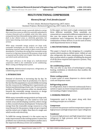
6.3 Design of compressor
The combination of air can beassumedtobereversible
polytropic process,
P.v=constant
Fig -1. Design of Compressor
The net work done by a compression cycle is shownby
Work input=
Also
T2=T1(p2-p1)(n-1)/n
Where,
n=constant or polytrophic index
m- mass flow rate of air
R= specific gas constant
T2=Air delivery temperature
T1=Air suction temperature
P2=Air delivery pressure
P1=Air suction pressure
CONCLUSION-
This paper is based on solving the live problems of
more power consumption. It contains the three
different units which are more expensive and low](https://image.slidesharecdn.com/irjet-v5i639-180713112334/85/IRJET-Multi-Functional-Compressor-3-320.jpg)
![International Research Journal of Engineering and Technology (IRJET) e-ISSN: 2395-0056
Volume: 05 Issue: 06 | June-2018 www.irjet.net p-ISSN: 2395-0072
© 2018, IRJET | Impact Factor value: 6.171 | ISO 9001:2008 Certified Journal | Page 190
efficient. The efficiency of the designed system can be
enhanced when it is converted into the actual product.
Many accessories can be attached to it for making it
more sophisticated. As the demand of electricity is
increasing day by day and the consumption is higher
than its production, so we should move towards
renewable sources of energy which are available in
abundance.
REFERENCES-
[1] Sunil A More at. Al.; Combined Air Refrigeration,
Air Conditioning And Water Dispenser Systems,
Jan 2018, IRJET
[2] S.M. Shaikh, “Performance Investigation of
Window Air Conditioner” IOSR Journal of Civil and
Mechanical Engineering (IOSR-JMCE) sISSN: 2278-
1684, PP: 32-37www.iosrjournals.org
[3] P.Dasthagiri and H.Ranganna, “Fabrication and
Analysis of Refrigerator cum Chilled Water
Dispenser” Advanced Engineering and Applied
Sciences: An International Journal, ISSN 2320–3927
[4] Himanshu, “Feasibility Study and Development of
Refrigerator cum Air Conditioner” International
Journal of Scientific and Research Publications,
Volume 4, Issue 12, December 2014 1 ISSN
22503153 .
[5] Dr. U. V.Kongre and A. R. Chiddarwar, “Testing
and Performance Analysis on Air Conditioner cum
Water Dispenser” International Journal of
Engineering Trends and Technology (IJETT) -
Volume4Issue4- April 2013
[6] B. Naveen, “waste heat recovery in r & ac systems”
internationaljournalofscienceandresearch(ijsr)ISSN
(online): 2319-7064
BIOGRAPHIES
Khemraj Beragi
M. Tech. Scholar,
Mechanical Engineering,
LNCT, Indore,(M.P)
Prof. Jitendra Jayant
Asst.Professor,
Mechanical Engineering,
LNCT,Indore, (M.P)
Photo](https://image.slidesharecdn.com/irjet-v5i639-180713112334/85/IRJET-Multi-Functional-Compressor-4-320.jpg)

This document describes the design of a multi-functional compressor system that can perform the functions of air conditioning, water cooling, and refrigeration simultaneously using a single compressor. The system aims to reduce energy consumption compared to separate systems for each function. It discusses the components and working principles of the system. The design details of the evaporator, condenser, and compressor are provided. The system offers benefits like lower power consumption, lower installation costs, and reduced space requirements compared to separate air conditioning, water cooling, and refrigeration systems. However, it is noted that the system has a lower capacity than large-scale industrial systems.


![Refrigeration_and_Air_conditioning_03-08-23[1] short.pdf](https://cdn.slidesharecdn.com/ss_thumbnails/refrigerationandairconditioning03-08-231short-240807114508-73019542-thumbnail.jpg?width=640&height=640&fit=bounds)


