Design and Implementation of Axi-Apb Bridge based on Amba 4.0
•
1 like•754 views

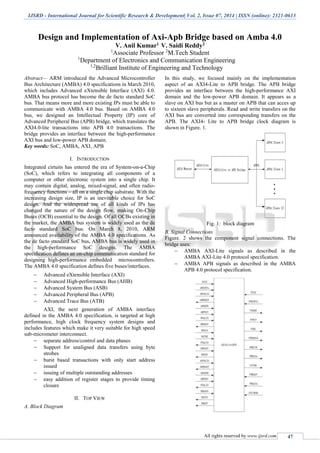
ARM introduced the Advanced Microcontroller Bus Architecture (AMBA) 4.0 specifications in March 2010, which includes Advanced eXtensible Interface (AXI) 4.0. AMBA bus protocol has become the de facto standard SoC bus. That means more and more existing IPs must be able to communicate with AMBA 4.0 bus. Based on AMBA 4.0 bus, we designed an Intellectual Property (IP) core of Advanced Peripheral Bus (APB) bridge, which translates the AXI4.0-lite transactions into APB 4.0 transactions. The bridge provides an interface between the high-performance AXI bus and low-power APB domain.
![Design and Implementation of Axi-Apb Bridge based on Amba 4.0
(IJSRD/Vol. 2/Issue 07/2014/012)
All rights reserved by www.ijsrd.com 48
C. AXI Handshake Mechanism
In AXI 4.0 specification, each channel h as a VALID and
READY signals for handshaking. The sour ce asserts
VALID when the control information or data is available.
The destination asserts READY when it can accept the
control information or data. Transfer occurs only when both
the VALID and READY are asserted. Figure. 3 shows all
possible cases of VALID/READ handshaking. Note that
when source asserts VALID, the corresponding control
information or data must also be available at the same time.
The arrows in Figure. 3 indicate when the transfer occurs. A
transfer takes place at the positive edge of clock. Therefore,
the source needs a register input to sample the READY
signal. In the same way, the destination needs a register
input to sa mple the VALID signal. Considering the
situation of Figure. 3(c), we assume the source and
destination use output registers instead of combination
circuit, they need one cycle to pull low VALID/READY and
sample the VALID/RE ADY again at T4 cycle. When they
sample the VALID/REA DY again at T4, there should be
another transfer which is an error. Therefore source and
destination should use combi national circuit as output. In
short, AXI protocol is suitable register input and
combinational output circuit.
The APB bridge buffers address, contr ol and data
from AXI4-Lite, drives the APB peripherals and returns data
and response signal to the AXI4-Lite. It decodes the address
using an internal address map to select the peripheral. The
bridge is designed to operate when the APB and AXI4-Lite
have independent clock frequency and phase. For every AXI
channel, invalid commands are not forwar ded and an error
response generated. That is once an periph eral accessed
does not exist, the APB bridge will generate DE CERR as
response through the response channel (read or write). And
if the target peripheral exists, but asserts PSLVERR, it will
give a SLVERR response.
Fig. 3: handshake mechanism
III. CLOCK DOM AIN CROSSING (CDC)
A clock domain crossing ( CDC), or simply clock crossing,
is when a signal crosses from o ne clock domain into
another[3]
. If a signal does not assert long enough and is not
registered, it may appear asynchronous on the incoming
clock boundary. Metastability happens when signal changes
within the setup/hold time window. Sync hronizing a signal
that crosses into a higher clocked domain can be
accomplished by registering the signal through a flip-flop
that is clocked by the source domain, thus holding the signal
long enough to be detected by the higher clocked destination
domain. Synchronizing a signal traversing into a slower
clock domain is more cumbersome[4]
. This typically requires
a register in each clock domain with a form of feedback
from the destination domain to the source domain ,
indicating that the signal was detected.
A. Metastability
Metastability cannot be avoided, but a solution for handling
the metastable signal enables proper functioning of the
design. The metastability occurrences can be predicted by
using the mean time between failures (MTBF) formula (1):
Where C1 and C2 are constants that depend on the
technology used to build the flip-flop; tMET is the duration
of the metastable output; and fclk and fdata are the
frequencies of the synchronous clock and the asynchronous
input, respectively.
B. Synchronizer
Designers can use special metastable hardened flops for
increasing the MTBF. For example, in Figure. 4, a
synchronizer flop is used following the signal DB. So,
instead of the metastable signal DB being used in the
function downstream as in Figure. 4, the stable signal DB2
is used in the logic downstream[8]
. In the AXI4-Lite to APB
bridge, we use synchronizer block designs for communicate
between the AXI and APB clock domain.
Fig. 4: two flip-flop synchronizer
IV. FINITE STATE MACHINE (FSM)
A finite state machine is a mathematical abstraction
sometimes used to design digital logic or computer
programs. It is a behavior model composed of a finite](data:image/gif;base64,R0lGODlhAQABAIAAAAAAAP///yH5BAEAAAAALAAAAAABAAEAAAIBRAA7)
Recommended
More Related Content
What's hot
What's hot (20)
Viewers also liked
Similar to Design and Implementation of Axi-Apb Bridge based on Amba 4.0
Similar to Design and Implementation of Axi-Apb Bridge based on Amba 4.0 (20)
More from ijsrd.com
More from ijsrd.com (20)
Recently uploaded
Recently uploaded (20)
Design and Implementation of Axi-Apb Bridge based on Amba 4.0
- 1. IJSRD - International Journal for Scientific Research & Development| Vol. 2, Issue 07, 2014 | ISSN (online): 2321-0613 All rights reserved by www.ijsrd.com 47 Design and Implementation of Axi-Apb Bridge based on Amba 4.0 V. Anil Kumar1 V. Saidi Reddy2 1 Associate Professor 2 M.Tech Student 1 Department of Electronics and Communication Engineering 1,2 Brilliant Institute of Engineering and Technology Abstract— ARM introduced the Advanced Microcontroller Bus Architecture (AMBA) 4.0 specifications in March 2010, which includes Advanced eXtensible Interface (AXI) 4.0. AMBA bus protocol has become the de facto standard SoC bus. That means more and more existing IPs must be able to communicate with AMBA 4.0 bus. Based on AMBA 4.0 bus, we designed an Intellectual Property (IP) core of Advanced Peripheral Bus (APB) bridge, which translates the AXI4.0-lite transactions into APB 4.0 transactions. The bridge provides an interface between the high-performance AXI bus and low-power APB domain. Key words: SoC, AMBA, AXI, APB I. INTRODUCTION Integrated cirtuits has entered the era of System-on-a-Chip (SoC), which refers to integrating all components of a computer or other electronic system into a single chip. It may contain digital, analog, mixed-signal, and often radio- frequency functions – all on a single chip substrate. With the increasing design size, IP is an inevitable choice for SoC design. And the widespread use of all kinds of IPs has changed the nature of the design flow, making On-Chip Buses (OCB) essential to the design. Of all OCBs existing in the market, the AMBA bus system is widely used as the de facto standard SoC bus. On March 8, 2010, ARM announced availability of the AMBA 4.0 specifications. As the de facto standard SoC bus, AMBA bus is widely used in the high-performance SoC designs. The AMBA specification defines an on-chip communication standard for designing high-performance embedded microcontrollers. The AMBA 4.0 specification defines five buses/interfaces. Advanced eXtensible Interface (AXI) Advanced High-performance Bus (AHB) Advanced System Bus (ASB) Advanced Peripheral Bus (APB) Advanced Trace Bus (ATB) AXI, the next generation of AMBA interface defined in the AMBA 4.0 specification, is targeted at high performance, high clock frequency system designs and includes features which make it very suitable for high speed sub-micrometer interconnect. separate address/control and data phases Support for unaligned data transfers using byte strobes burst based transactions with only start address issued issuing of multiple outstanding addresses easy addition of register stages to provide timing closure II. TOP VIEW A. Block Diagram In this study, we focused mainly on the implementation aspect of an AXI4-Lite to APB bridge. The APB bridge provides an interface between the high-performance AXI domain and the low-power APB domain. It appears as a slave on AXI bus but as a master on APB that can acces up to sixteen slave peripherals. Read and write transfers on the AXI bus are converted into corresponding transfers on the APB. The AXI4- Lite to APB bridge clock diagram is shown in Figure. 1. Fig. 1: block diagram B. Signal Connections Figure. 2 shows the component signal connections. The bridge uses: AMBA AXI-Lite signals as described in the AMBA AXI-Lite 4.0 protocol specification. AMBA APB signals as described in the AMBA APB 4.0 protocol specification.
- 2. Design and Implementation of Axi-Apb Bridge based on Amba 4.0 (IJSRD/Vol. 2/Issue 07/2014/012) All rights reserved by www.ijsrd.com 48 C. AXI Handshake Mechanism In AXI 4.0 specification, each channel h as a VALID and READY signals for handshaking. The sour ce asserts VALID when the control information or data is available. The destination asserts READY when it can accept the control information or data. Transfer occurs only when both the VALID and READY are asserted. Figure. 3 shows all possible cases of VALID/READ handshaking. Note that when source asserts VALID, the corresponding control information or data must also be available at the same time. The arrows in Figure. 3 indicate when the transfer occurs. A transfer takes place at the positive edge of clock. Therefore, the source needs a register input to sample the READY signal. In the same way, the destination needs a register input to sa mple the VALID signal. Considering the situation of Figure. 3(c), we assume the source and destination use output registers instead of combination circuit, they need one cycle to pull low VALID/READY and sample the VALID/RE ADY again at T4 cycle. When they sample the VALID/REA DY again at T4, there should be another transfer which is an error. Therefore source and destination should use combi national circuit as output. In short, AXI protocol is suitable register input and combinational output circuit. The APB bridge buffers address, contr ol and data from AXI4-Lite, drives the APB peripherals and returns data and response signal to the AXI4-Lite. It decodes the address using an internal address map to select the peripheral. The bridge is designed to operate when the APB and AXI4-Lite have independent clock frequency and phase. For every AXI channel, invalid commands are not forwar ded and an error response generated. That is once an periph eral accessed does not exist, the APB bridge will generate DE CERR as response through the response channel (read or write). And if the target peripheral exists, but asserts PSLVERR, it will give a SLVERR response. Fig. 3: handshake mechanism III. CLOCK DOM AIN CROSSING (CDC) A clock domain crossing ( CDC), or simply clock crossing, is when a signal crosses from o ne clock domain into another[3] . If a signal does not assert long enough and is not registered, it may appear asynchronous on the incoming clock boundary. Metastability happens when signal changes within the setup/hold time window. Sync hronizing a signal that crosses into a higher clocked domain can be accomplished by registering the signal through a flip-flop that is clocked by the source domain, thus holding the signal long enough to be detected by the higher clocked destination domain. Synchronizing a signal traversing into a slower clock domain is more cumbersome[4] . This typically requires a register in each clock domain with a form of feedback from the destination domain to the source domain , indicating that the signal was detected. A. Metastability Metastability cannot be avoided, but a solution for handling the metastable signal enables proper functioning of the design. The metastability occurrences can be predicted by using the mean time between failures (MTBF) formula (1): Where C1 and C2 are constants that depend on the technology used to build the flip-flop; tMET is the duration of the metastable output; and fclk and fdata are the frequencies of the synchronous clock and the asynchronous input, respectively. B. Synchronizer Designers can use special metastable hardened flops for increasing the MTBF. For example, in Figure. 4, a synchronizer flop is used following the signal DB. So, instead of the metastable signal DB being used in the function downstream as in Figure. 4, the stable signal DB2 is used in the logic downstream[8] . In the AXI4-Lite to APB bridge, we use synchronizer block designs for communicate between the AXI and APB clock domain. Fig. 4: two flip-flop synchronizer IV. FINITE STATE MACHINE (FSM) A finite state machine is a mathematical abstraction sometimes used to design digital logic or computer programs. It is a behavior model composed of a finite
- 3. Design and Implementation of Axi-Apb Bridge based on Amba 4.0 (IJSRD/Vol. 2/Issue 07/2014/012) All rights reserved by www.ijsrd.com 49 number of states, transitions between those states, and actions, similar to a flow graph in which one can inspect the way logic runs when certain conditions are met[10] . The state transition diagram is a picture of our state machine model. Figure. 5 is the state transition diagram of our FSM. The state machine operates through the following states: IDLE. This is the default state of the FSM. WRITE_SETUP. When a write transfer request is asserted, the FSM moves into the WRITE_SETUP state. READ_SETUP. When a read transfer request is asserted, the FSM moves into the READ_SETUP state. WRIET_ACCESS. The enable signal, PENABLE, is asserted in the WRITE_ACCESS state. READ_ACCESS. The enable signal, PENABLE, is asserted in the READ_ACCESS state. WRITE_WAIT. When the AXI write response channel is not ready for receiving signal BRESP, then stay in WRITE_WAIT state. READ_WAIT. When the AXI read data channel is not ready for receiving signal RRESP, then stay in READ_WAIT state. States READ_WAIT and WRITE_WAIT are added, because the APB is not pipelined, wait states are added during transfers between the APB and AXI interface. According AXI specification, the read address channel, write address channel and write data channel are completely independent. Each channel has a set of forward signals and a feedback signal for handshaking. A read and a write requests may be issued simultaneously (AWVALID/WVALID and ARVALID are asserted high simultaneously) from AXI4-Lite, the AXI4-Lite to APB bridge will give more priority to the read request than to the write request. That is, when both write and read requests are valid, the write request is initiated on APB after the read is requested on APB. V. SIMULATION & IMPLEMENTATION The timing diagram shown in Figure. 5 illustrate the AXI4- Lite to APB bridge operation for various read and write transfers. It shows that when both read and write requests are active, read is given more priority. Before Static Timing Analysis (STA), it is necessary to inform the EDA tools that ACLK and PCLK are two asynchronous clock domains. Fig. 5: typical read and write transfer VI. CONCLUSION In this study, we provide an implementation of AXI4-Lite to APB bridge which has the following features: 32-bit AXI slave and APB master interfaces. PCLK clock domain completely independent of ACLK clock domain. support up to 16 APB peripherals. support the PREADY signal which translate to wait states on AXI. an error on any transfer results in SLVERR as the AXI read/write response. REFERENCES [1] ARM, "AMBA Protocol Specification 4.0", www.arm.com, 2010. [2] Ying-Ze Liao, "System Design and Implementation of AXI Bus", National Chiao Tung University, October 2007. [3] Clifford E. Cummings, "Coding And Scripting Techniques For FSM Designs With Synthesis- Optimized, Glitch-Free Outputs," SNUG (Synopsys Users Group Boston, MA 2000) Proceedings, September 2000. [4] Clifford E. Cummings, “Synthesis and Scripting Techniques for Designing Multi-Asynchronous Clock Designs,” SNUG 2001 [5] Chris Spear, "SystemVerilog for Verification, 2nd Edition", Springer, www.springeronline.com, 2008. [6] Lahir, K., Raghunathan A., Lakshminarayana G., “LOTTERYBUS: a new high-performance communication architecture for system-on-chip deisgns,” in Proceedings of Design Automation Conference, 2001.
- 4. Design and Implementation of Axi-Apb Bridge based on Amba 4.0 (IJSRD/Vol. 2/Issue 07/2014/012) All rights reserved by www.ijsrd.com 50 [7] Sanghun Lee, Chanho Lee, Hauk-Jae Lee, “A new multi-channel on-chip-bus architecture for system-on- chips,” in Proceedings of IEEE international SOC Conference, September 2004. [8] Martino Ruggiero, Federico Angelina, Francesco Palette, Divide Bertozzi, Luca 86