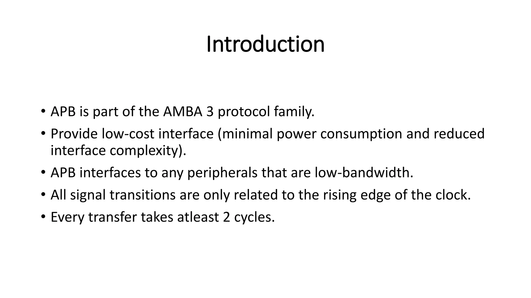
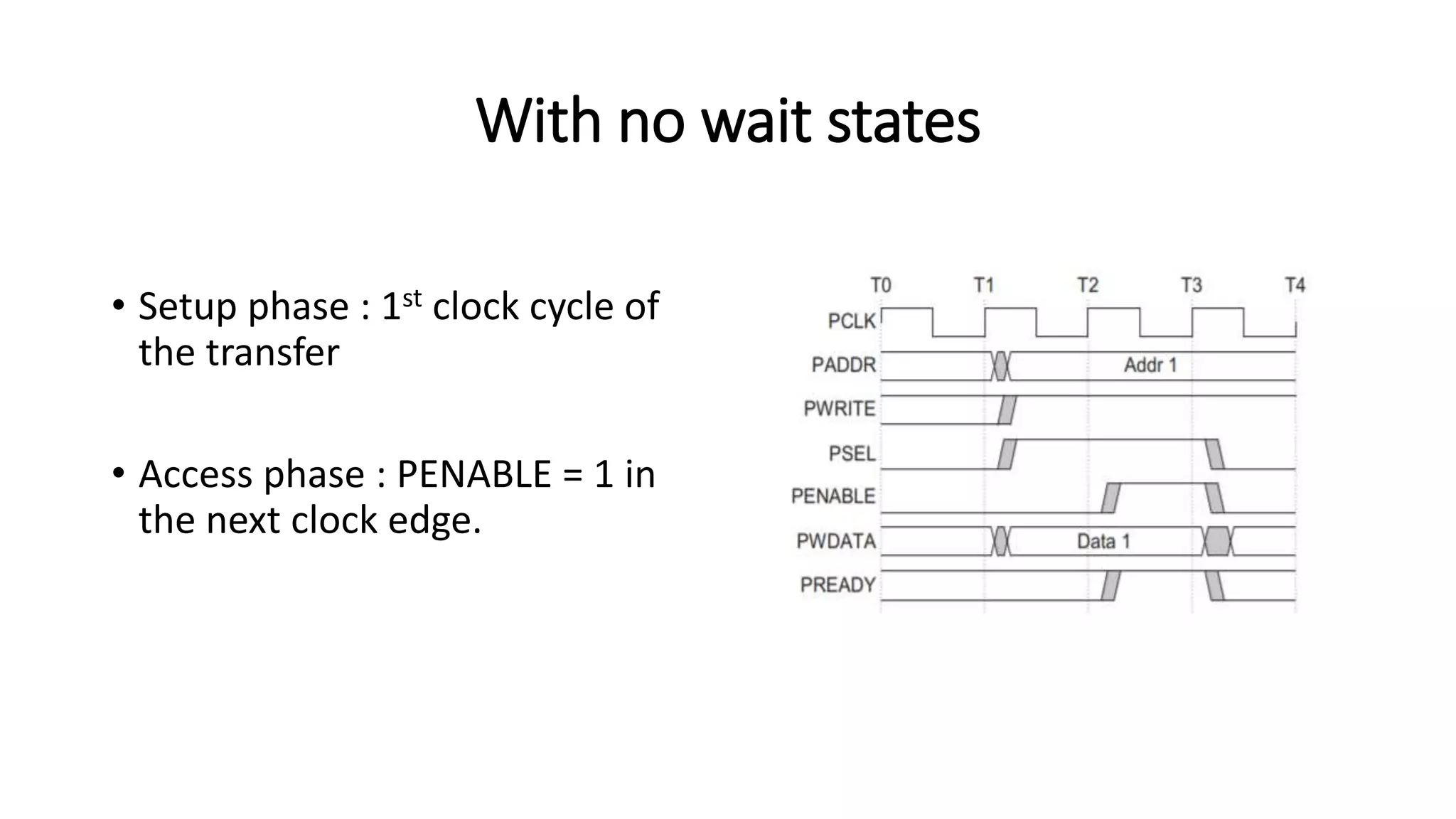
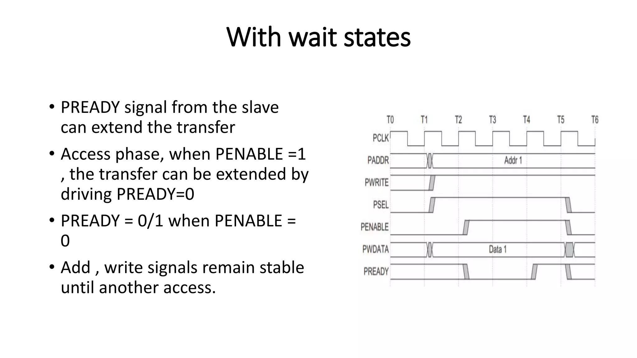
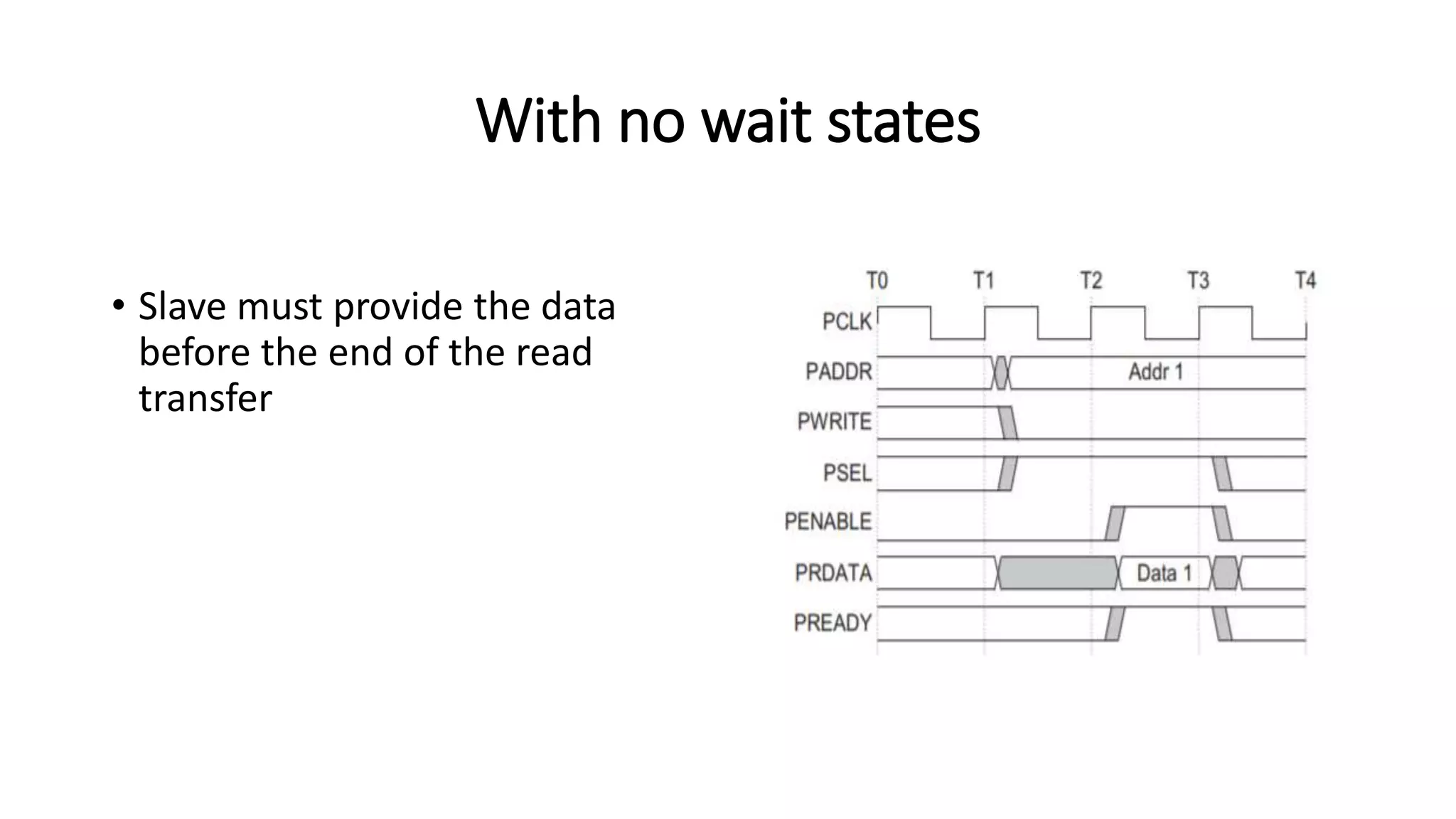
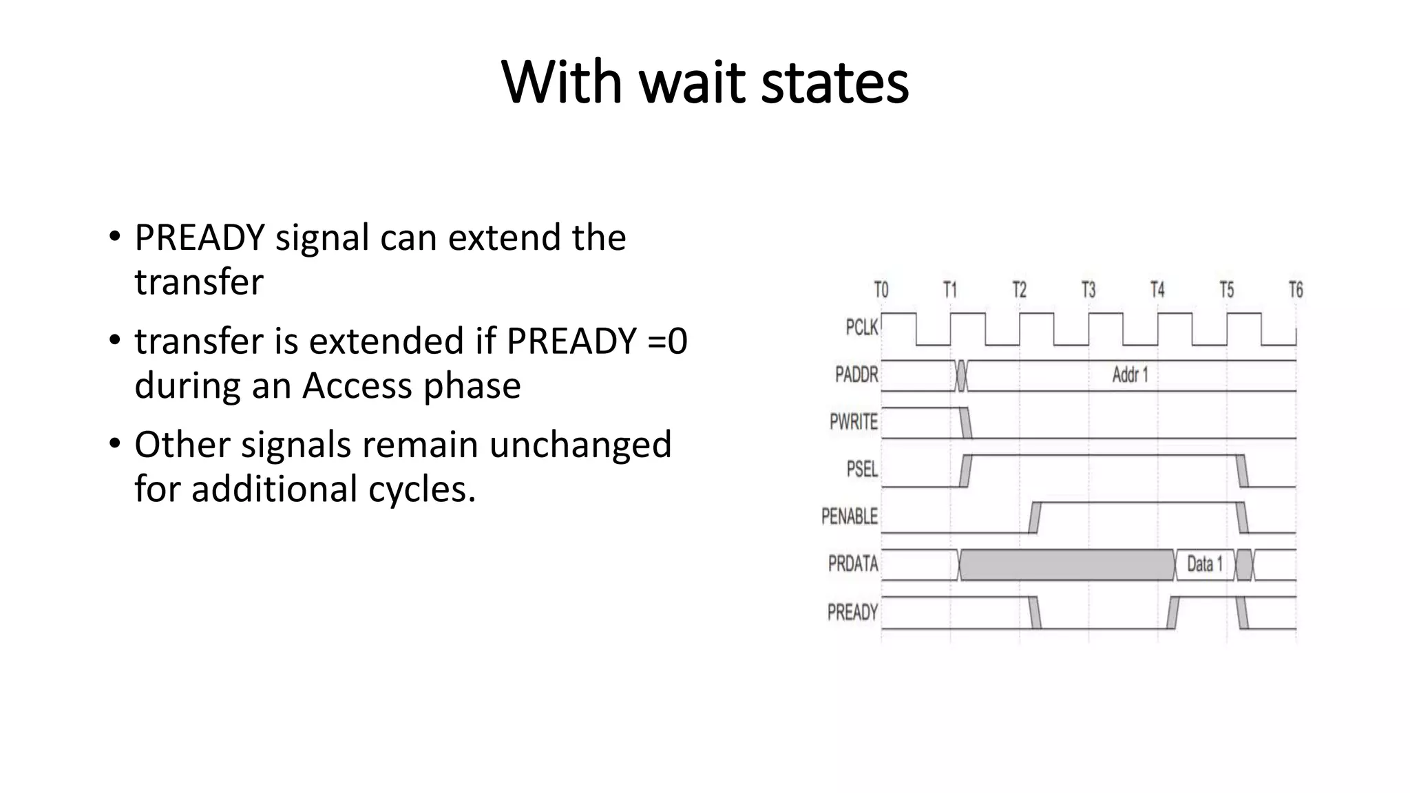
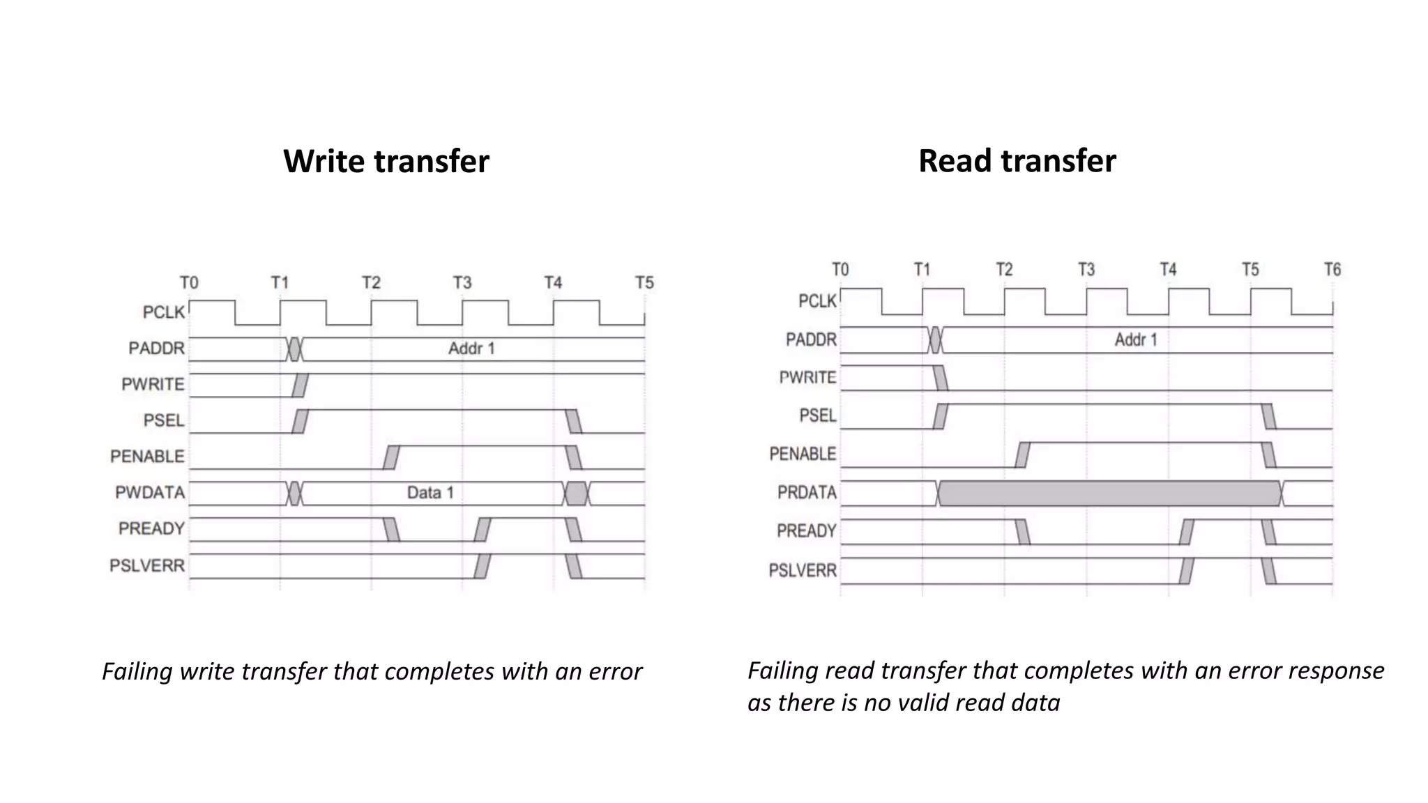
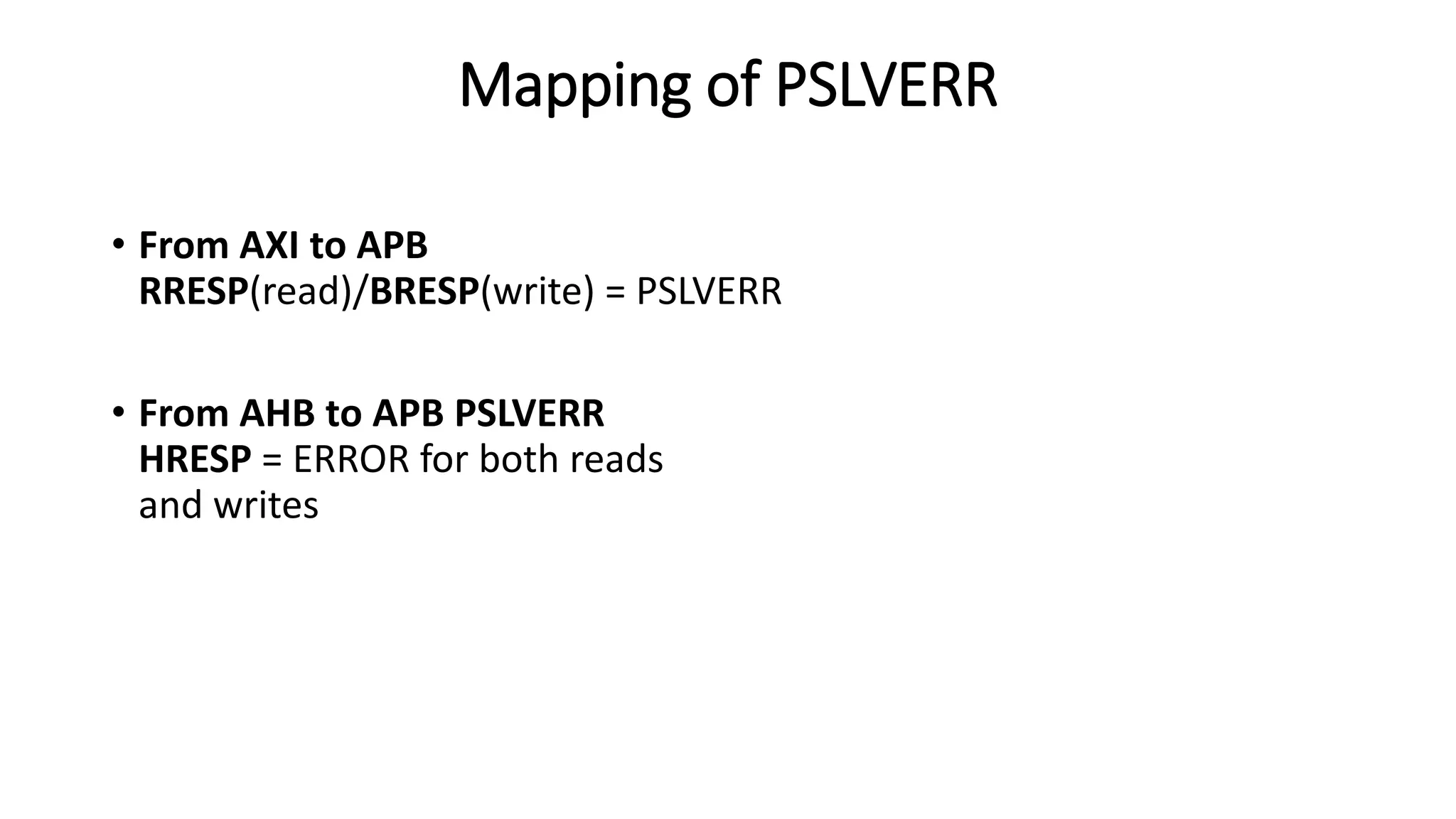
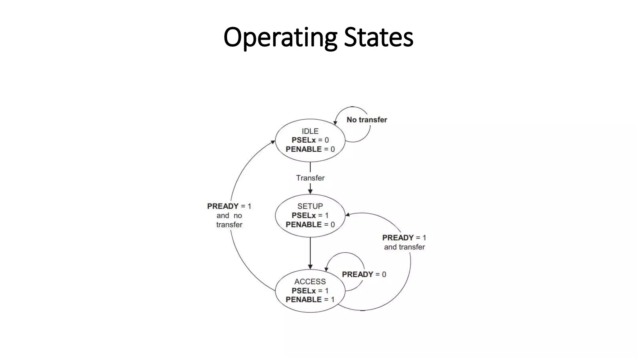
AMBA 3 APB Protocol
-Swetha
Introduction
• APB is part of the AMBA 3 protocol family.
• Provide low-cost interface (minimal power consumption and reduced
interface complexity).
• APB interfaces to any peripherals that are low-bandwidth.
• All signal transitions are only related to the rising edge of the clock.
• Every transfer takes atleast 2 cycles.
Transfers
There are 2 types of transfers
Write transfers • With no wait states
• With wait states.
Read transfers • With no wait states
• With wait states.
With no wait states
• Setup phase : 1st clock cycle of
the transfer
• Access phase : PENABLE = 1 in
the next clock edge.
With wait states
• PREADY signal from the slave
can extend the transfer
• Access phase, when PENABLE =1
, the transfer can be extended by
driving PREADY=0
• PREADY = 0/1 when PENABLE =
0
• Add , write signals remain stable
until another access.
With no wait states
• Slave must provide the data
before the end of the read
transfer
With wait states
• PREADY signal can extend the
transfer
• transfer is extended if PREADY =0
during an Access phase
• Other signals remain unchanged
for additional cycles.
Error response
• PSLVERR to indicate an error condition on an APB transfer.
• Occur on both read and write transactions.
• PSLVERR = Valid during last cycle when PSEL, PENABLE, PREADY = 1
• PSLVERR = 0 ; when any of PSEL, PENABLE, or PREADY= 0
• There is no requirement for the peripheral to drive the data bus to all 0s for
a read error; it can return invalid data
• Where a peripheral does not include this PSLVERR pin then the appropriate
input to the APB bridge is tied to 0
.
Write transfer
.
Read transfer
Failing write transfer that completes with an error Failing read transfer that completes with an error response
as there is no valid read data
Mapping of PSLVERR
• From AXI to APB
RRESP(read)/BRESP(write) = PSLVERR
• From AHB to APB PSLVERR
HRESP = ERROR for both reads
and writes
Operating States
Thank you
.

AMBA 3 APB Protocol

  • 1.
    AMBA 3 APBProtocol -Swetha
  • 2.
    Introduction • APB ispart of the AMBA 3 protocol family. • Provide low-cost interface (minimal power consumption and reduced interface complexity). • APB interfaces to any peripherals that are low-bandwidth. • All signal transitions are only related to the rising edge of the clock. • Every transfer takes atleast 2 cycles.
  • 3.
    Transfers There are 2types of transfers Write transfers • With no wait states • With wait states. Read transfers • With no wait states • With wait states.
  • 4.
    With no waitstates • Setup phase : 1st clock cycle of the transfer • Access phase : PENABLE = 1 in the next clock edge.
  • 5.
    With wait states •PREADY signal from the slave can extend the transfer • Access phase, when PENABLE =1 , the transfer can be extended by driving PREADY=0 • PREADY = 0/1 when PENABLE = 0 • Add , write signals remain stable until another access.
  • 6.
    With no waitstates • Slave must provide the data before the end of the read transfer
  • 7.
    With wait states •PREADY signal can extend the transfer • transfer is extended if PREADY =0 during an Access phase • Other signals remain unchanged for additional cycles.
  • 8.
    Error response • PSLVERRto indicate an error condition on an APB transfer. • Occur on both read and write transactions. • PSLVERR = Valid during last cycle when PSEL, PENABLE, PREADY = 1 • PSLVERR = 0 ; when any of PSEL, PENABLE, or PREADY= 0 • There is no requirement for the peripheral to drive the data bus to all 0s for a read error; it can return invalid data • Where a peripheral does not include this PSLVERR pin then the appropriate input to the APB bridge is tied to 0
  • 9.
    . Write transfer . Read transfer Failingwrite transfer that completes with an error Failing read transfer that completes with an error response as there is no valid read data
  • 10.
    Mapping of PSLVERR •From AXI to APB RRESP(read)/BRESP(write) = PSLVERR • From AHB to APB PSLVERR HRESP = ERROR for both reads and writes
  • 11.
  • 12.