Z Score,T Score, Percential Rank and Box Plot Graph
Digital Communications 3rd Quarter
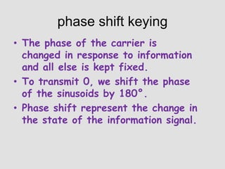
1. phase shift keying
• The phase of the carrier is
changed in response to information
and all else is kept fixed.
• To transmit 0, we shift the phase
of the sinusoids by 180°.
• Phase shift represent the change in
the state of the information signal.
3. Phasor diagram
A phasor diagram is used to show the phase
relationships between two or more sine waves
having the same frequency.
4. Quarternary or QUADRATURE PHASE
SHIFT KEYING (QPSK)
• With QPSK, four output phases are
possible for a single carrier frequency.
• The binary input data for QPSK are
combined into groups of 2.
7. TRELLIS code modulation
Transmission rates of 56 kbps require a signal-to-noise ratio of
53 dB, which is virtually impossible to achieve over a standard
telephone circuit.
Data transmission rates in excess of 56 kbps can be
achieved, however, over standard telephone circuits using an
encoding technique called trellis code modulation (TCM).
Dr. Ungerboeck at IBM Zuerich Research Laboratory
developed TCM, which involves using convolutional (tree) codes,
which combines encoding and modulation to reduce the
probability of error, thus improving the bit error performance.
I WILL CERTAINLY INCLUDE THIS IN THE 3RD QUARTER
EXAMINATION. PLEASE STUDY, IT’S FOR YOUR OWN GOOD NOT
MINE. RESEARCH MORE IF NECESSARY.
8. QUADRATURE AMPLITUDE
MODULATION (QAM)
• Is a form of digital modulation similar to
PSK except the digital information is
contained in both the amplitude and the
phase of the transmitted carrier.
9. 8-QAM Truth table
Binary Input
Output Phase
Output Amplitude
Q
I
C
0
0
0
-135°
0.765 V
0
0
1
-135°
1.848 V
0
1
0
-45°
0.765 V
0
1
1
-45°
1.848 V
1
0
0
135°
0.765 V
1
0
1
135°
1.848 V
1
1
0
45°
0.765 V
1
1
1
45°
1.848 V
Research for the concept of 16-QAM.
10. BANDWIDTH EFFICIENCY
Is often used to compute the performance of
one digital modulation technique to another. In
essence, bandwidth efficiency is the ratio of the
transmission bit rate to the minimum
bandwidth required for a particular modulation
scheme.
11. :::
• For 16-PSK and a transmission system
with a 10 kHz bandwidth, determine the
maximum bit rate.
12. CARRIER RECOVERY
Is the process of extracting a phase-coherent
reference carrier from a receiver signal.
I WILL CERTAINLY INCLUDE THIS IN THE 3RD QUARTER EXAMINATION. PLEASE STUDY,
IT’S FOR YOUR OWN GOOD NOT MINE. RESEARCH MORE IF NECESSARY.
13. Squaring loop
A common method of achieving carrier recovery for BPSK is
the squaring loop. The received BPSK waveform is filtered and
then squared. The filtering reduces the spectral width of the
received noise. The squaring circuit removes the modulation
and generates the second harmonic of the carrier frequency.
I WILL CERTAINLY INCLUDE THIS IN THE 3RD QUARTER EXAMINATION. PLEASE STUDY, IT’S
FOR YOUR OWN GOOD NOT MINE. RESEARCH MORE IF NECESSARY.
14. COSTAS LOOP
A second method of carrier recovery is the Costas,
or quadrature loop. This recovery scheme uses two
parallel tracking loops (I and Q) simultaneously to
derive the product of the I and Q components of the
signal that drives the VCO.
I WILL CERTAINLY INCLUDE THIS IN THE 3RD QUARTER EXAMINATION. PLEASE
STUDY, IT’S FOR YOUR OWN GOOD NOT MINE. RESEARCH MORE IF
NECESSARY.
15. Remodulator
A third method of achieving recovery of a phase and frequency coherent
carrier is the remodulator. The remodulator produces a loop error voltage
that is proportional to twice the phase error between the incoming signal
and the VCO signal. The remodulator has a faster acquisition time than
either the squaring or the Costas loops.
I WILL CERTAINLY INCLUDE THIS IN THE 3RD QUARTER EXAMINATION.
PLEASE STUDY, IT’S FOR YOUR OWN GOOD NOT MINE. RESEARCH MORE
IF NECESSARY.
16. probability of error and bit error rate
Probability of error is a theoretical expectation
of the bit error rate for a given system.
Bit Error Rate is an empirical record of a
system’s actual bit error performance.
17. EXAMPLE:::
For a QPSK system and the given parameters, determine:
a.
Carrier power in dBm.
b.
Noise power in dBm.
c.
Noise power density in dBm.
d.
Energy per bit in dBJ.
e.
Carrier-to-noise ratio in dB.
f.
Eb/No ratio.
C= 10-12 W
N = 1.2 x 10⁻¹⁴ W
fb = 60 kbps
B= 120 kHz
18. Pulse modulation:
Pulse modulation consists essentially of
sampling analog information signals and then
converting those samples into discrete pulses.
19. Sampling
The signal is sampled at regular intervals
such that each sample is proportional to
the amplitude of signal at that instant. This
technique is called “sampling”.
20. Sampling
There are 3 sampling methods:
Ideal - an impulse at each
sampling instant
Natural - a pulse of short width
with varying amplitude
Flat top - sample and hold, like
natural but with single amplitude
value
20
21.
22. Sampling Rate
• Nyquist showed that it is possible to
reconstruct a band-limited signal from
periodic samples, as long as the sampling
rate is at least twice the frequency of the of
highest frequency component of the signal
22
23. PAM
The amplitude of a constant width, constantposition pulse is varied according to the
amplitude of the sample of the analog signal.