SlideShare a Scribd company logo
1 of 15
Part B | Chapter 4 | Fiber Optic links :
Regenerative regenerators, Digital Links-link power and rise time budget analysis.
Analog links, C/N ration analysis. Coherent link – Homodyne and heterodyne
detection schemes. WDM operational principle of WDM. DWDM. Concepts and
components used for all optical for all optical Networks.
Regenerative Repeaters:
A repeater is a device in which signal processing is performed, i.e., received digital
signals are amplified, reshaped, retimed, and retransmitted. In other words, these are
used over digital links (transmission systems). The block diagram for the same is as
below:
The attenuated and dispersed optical pulse train is detected and amplified in the
receiver unit. This consists of a photodiode followed by a low-noise preamplifier. The
electrical signal thus acquired is given a further increase in power level in a main
amplifier prior to reshaping in order to compensate for the transfer characteristic of the
optical fiber (and the amplifier) using an equalizer.
Accurate timing (clock) information is then obtained from the amplified and equalized
waveform using a timing extraction circuit such as a phase-locked loop (PLL). This
enables precise operation of the following regenerator circuit within the bit intervals of
the original pulse train. The function of the regenerator circuit is to reconstitute the
originally transmitted pulse train, ideally without error. The pulse train is sampled at a
regular frequency equal to the bit rate, and at each sample instant a decision is made of
the most probable symbol being transmitted. The signal at the moment is in electrical
form and needs to be converted to optical form before it is fed back into the optical
fiber. This is taken care of using the drive circuit for the optical source which is either an
LED or a LASER depending on the kind of input that was present in the optical fiber.
This is an advantage over the analog transmission systems where the concept of
regenerative repeaters doesn’t exist.
Digital Links – link power and rise time budget analysis :
Solution is available in page no 323 to 331
Analog link
Solution is available in page no 359
C/N Ration analysis
Solution is available in page no 360
WDM optional principle is available in 4 sheet notes
In fiber-optic communications, wavelength-division multiplexing (WDM) is a
technology which multiplexes a number of optical carrier signals onto a single optical
fiber by using different wavelengths (i.e., colors) of laser light. This technique
enables bidirectionalcommunications over one strand of fiber, as well as multiplication
of capacity.
The term wavelength-division multiplexing is commonly applied to an optical carrier
(which is typically described by its wavelength), whereas frequency-division
multiplexing typically applies to a radio carrier (which is more often described
by frequency). Sincewavelength and frequency are tied together through a simple directly
inverse relationship, in which the product of frequency and wavelength equals c (the
propagation speed of light), the two terms actually describe the same concept.
A WDM system uses a multiplexer at the transmitter to join the signals together, and
a demultiplexer at thereceiver to split them apart. With the right type of fiber it is
possible to have a device that does both simultaneously, and can function as an optical
add-drop multiplexer. The optical filtering devices used have conventionally
been etalons (stable solid-state single-frequency Fabry–Pérot interferometers in the form
of thin-film-coated optical glass).
The concept was first published in 1978, and by 1980 WDM systems were being realized
in the laboratory. The first WDM systems combined only two signals. Modern systems
can handle up to 160 signals and can thus expand a basic 10 Gbit/s system over a single
fiber pair to over 1.6 Tbit/s.
WDM systems are popular with telecommunications companies because they allow
them to expand the capacity of the network without laying more fiber. By using WDM
and optical amplifiers, they can accommodate several generations of technology
development in their optical infrastructure without having to overhaul the backbone
network. Capacity of a given link can be expanded simply by upgrading the
multiplexers and demultiplexers at each end.
DWDM :
Dense wavelength division multiplexing (DWDM) is a fiber-optic transmission
technique that employs light wavelengths to transmit data parallel-by-bit or serial-by-
character
How does DWDM fair better :
► No O-E-O required
► Protocol & Bit Rate independence
► Increased overall capacity at much lower cost
 Current fiber plant investment can be optimized by a factor of at least 32
► Transparency
 Physical layer architecture  supports both TDM and data formats such
as ATM, Gigabit Ethernet, etc.
► Scalability
 Utilize abundance of dark fibers in metropolitan areas and enterprise
networks
Coherent link-Homodyne and Heterodyne detection schemes:
Coherent detection schemes are used in optical fiber communication as the direct
detection schemes employed (PIN Photodetector) varies only with the intensity (Power)
of the optical signal thus hindering the sensitivity and bandwidth capabilities of the
detector. The onus in direct detection scheme was to consider only the power level of
the optical signal ignoring the phase and frequency parameters by modulating the light
intensity with the input electrical signal voltage.
However in the coherent detection mode, the optical signal can be modulated based
frequency, amplitude or phase improving the sensitivity of the detector and enhancing
the bandwidth capabilities of the optical signal. This method along with the advantages
brings to the fore the need to have tuned semiconductor laser to produce coherent
output with as less spectral width as possible capable of being used in a single mode
optical fiber, a proper coding (NRZ, RZ, Manchester) method for the data to be
impressed upon the optical signal.
Block of optical coherent system of modulation and detection scheme:
In case of the modulation of the transmitting optical signal, the optical signal is
modulated either by ASK, PSK or FSK. In direct detection scheme, the signal is
amplitude modulated based on the electrical signal input which carries the information
and hence the detection is proportional to the intensity of the optical signal. However in
case of the coherent detection scheme, the incoming optical signal at the receiver end is
mixed with a wave generated by a local oscillator and this is done before the detection
by the photo-detectors take place and on the surface of the photo-detector.
If the frequency of the signal carrier and that of the local oscillator is same, then the
system is said to be a homodyne coherent detection scheme. Thus either the PSK or
ASK can be used while transmission modulation is being taken care as FSK is ruled out
here. Thus the output is a function of the intensities of the local oscillator wave and the
source optical signal with the output taking the form, where the
phase difference between source optical signal and that of the local oscillator is given by
and Ps, Plo are the intensities of the signals.
A sample block diagram for the homodyne coherent detection scheme is as below:
The advantage of the homodyne scheme is that the output frequency is brought to the
baseband level and no further electrical demodulation is necessary. Thus it is a highly
sensitive detection system along with providing high bandwidth capabilities. However
to manage the same frequency between the source and the local oscillator waves, it
becomes a difficult requirement. Also since the phase of the two waves is locked, a
requirement for the PLL is also necessary.
If the frequency of the signal carrier and that of the local oscillator is different, then the
system is said to be a heterodyne coherent detection scheme. Thus the phase
difference between the source and local oscillator signal becomes important and the
final output looks like this: .
A sample block diagram of the heterodyne coherent detection scheme is as below:
Though it doesn’t introduce the difficulty of having the systems to produce the same
frequency for source and local oscillator signals, the sensitivity decreases and a -3Db
degradation is introduced.
Digital Links-link power and rise time budget analysis :
Link Power Budgeted :
Rise Time Budgeted :
Analog links:
C/N ration analysis :
Concepts and components used for all optical for all optical Networks.
Available in page no 383
► TTrraannssmmiittttiinngg SSiiddee
 LLaasseerrss wwiitthh pprreecciissee ssttaabbllee wwaavveelleennggtthhss
 OOppttiiccaall MMuullttiipplleexxeerrss
► OOnn tthhee LLiinnkk
 OOppttiiccaall ffiibbeerr
 OOppttiiccaall aammpplliiffiieerrss
► RReecceeiivviinngg SSiiddee
 PPhhoottoo ddeetteeccttoorrss
 OOppttiiccaall DDeemmuullttiipplleexxeerrss
► OOppttiiccaall aadddd//ddrroopp mmuullttiipplleexxeerrss

More Related Content

What's hot

Circuits for Optical Based Line of Sight Voice Communication
Circuits for Optical Based Line of Sight Voice CommunicationCircuits for Optical Based Line of Sight Voice Communication
Circuits for Optical Based Line of Sight Voice Communication
journalBEEI
 
Tsinghua visit
Tsinghua visitTsinghua visit
Tsinghua visit
wtyru1989
 

What's hot (20)

ICACC Presentation
ICACC PresentationICACC Presentation
ICACC Presentation
 
EC8751 Optical Communication-Unit 1-introduction to optical fibers
EC8751 Optical Communication-Unit 1-introduction to optical fibersEC8751 Optical Communication-Unit 1-introduction to optical fibers
EC8751 Optical Communication-Unit 1-introduction to optical fibers
 
Unit II- TRANSMISSION CHARACTERISTIC OF OPTICAL FIBER
Unit II- TRANSMISSION CHARACTERISTIC OF OPTICAL FIBER 	Unit II- TRANSMISSION CHARACTERISTIC OF OPTICAL FIBER
Unit II- TRANSMISSION CHARACTERISTIC OF OPTICAL FIBER
 
Quantum dot laser
Quantum dot laserQuantum dot laser
Quantum dot laser
 
Ofc
OfcOfc
Ofc
 
optical communication Unit 3
optical communication Unit 3optical communication Unit 3
optical communication Unit 3
 
Drive circuitry for LEDs and LASER
Drive circuitry for LEDs and LASERDrive circuitry for LEDs and LASER
Drive circuitry for LEDs and LASER
 
Mutual coupling
Mutual couplingMutual coupling
Mutual coupling
 
Circuits for Optical Based Line of Sight Voice Communication
Circuits for Optical Based Line of Sight Voice CommunicationCircuits for Optical Based Line of Sight Voice Communication
Circuits for Optical Based Line of Sight Voice Communication
 
3 d single gaas co axial nanowire solar cell for nanopillar-array photovoltai...
3 d single gaas co axial nanowire solar cell for nanopillar-array photovoltai...3 d single gaas co axial nanowire solar cell for nanopillar-array photovoltai...
3 d single gaas co axial nanowire solar cell for nanopillar-array photovoltai...
 
A Novel Design of a Miniature Metamaterial Antenna for RFID Reader Applications
A Novel Design of a Miniature Metamaterial Antenna for RFID Reader ApplicationsA Novel Design of a Miniature Metamaterial Antenna for RFID Reader Applications
A Novel Design of a Miniature Metamaterial Antenna for RFID Reader Applications
 
Optical communication and Equipments
Optical communication and EquipmentsOptical communication and Equipments
Optical communication and Equipments
 
All optical switch and tunable filter with photorefractive crystal
All optical switch and tunable filter with photorefractive crystalAll optical switch and tunable filter with photorefractive crystal
All optical switch and tunable filter with photorefractive crystal
 
Formats for coherent optical communications -OPTICAL COMMUNICATIONS
Formats for coherent optical communications -OPTICAL COMMUNICATIONSFormats for coherent optical communications -OPTICAL COMMUNICATIONS
Formats for coherent optical communications -OPTICAL COMMUNICATIONS
 
Tsinghua visit
Tsinghua visitTsinghua visit
Tsinghua visit
 
Bragg grating all optical switches
Bragg grating all optical switchesBragg grating all optical switches
Bragg grating all optical switches
 
Power harvesting metamaterial
Power harvesting metamaterialPower harvesting metamaterial
Power harvesting metamaterial
 
Optical Wavelength converters
Optical Wavelength convertersOptical Wavelength converters
Optical Wavelength converters
 
Optical communication unit 1
Optical communication unit 1Optical communication unit 1
Optical communication unit 1
 
fiber-optics-communications-optical-detectors
fiber-optics-communications-optical-detectorsfiber-optics-communications-optical-detectors
fiber-optics-communications-optical-detectors
 

Viewers also liked

12nuit.com
12nuit.com12nuit.com
12nuit.com
12nuit
 
Repository pada debian linux
Repository pada debian linuxRepository pada debian linux
Repository pada debian linux
febrimaulanawme
 
Cara menginstall debian dalam virtual box
Cara menginstall debian dalam virtual boxCara menginstall debian dalam virtual box
Cara menginstall debian dalam virtual box
febrimaulanawme
 
EPAFrackAssmt_Brief_Final
EPAFrackAssmt_Brief_FinalEPAFrackAssmt_Brief_Final
EPAFrackAssmt_Brief_Final
John Noël
 
Texas Aquifer Exemptions - Clean Water Action august 2016
Texas Aquifer Exemptions - Clean Water Action august 2016Texas Aquifer Exemptions - Clean Water Action august 2016
Texas Aquifer Exemptions - Clean Water Action august 2016
John Noël
 
Menambah aplikasi di virtual box
Menambah aplikasi di virtual boxMenambah aplikasi di virtual box
Menambah aplikasi di virtual box
febrimaulanawme
 

Viewers also liked (13)

All optical circuits and for digital logic
All optical circuits and for digital logicAll optical circuits and for digital logic
All optical circuits and for digital logic
 
Optical Fiber
Optical Fiber Optical Fiber
Optical Fiber
 
Ecc3601 lecture 2
Ecc3601 lecture 2Ecc3601 lecture 2
Ecc3601 lecture 2
 
Optical fibre communication basics
Optical fibre communication basicsOptical fibre communication basics
Optical fibre communication basics
 
Editor nano
Editor nanoEditor nano
Editor nano
 
12nuit.com
12nuit.com12nuit.com
12nuit.com
 
Repository pada debian linux
Repository pada debian linuxRepository pada debian linux
Repository pada debian linux
 
El món prehistòric power point
El món prehistòric power pointEl món prehistòric power point
El món prehistòric power point
 
Cara menginstall debian dalam virtual box
Cara menginstall debian dalam virtual boxCara menginstall debian dalam virtual box
Cara menginstall debian dalam virtual box
 
EPAFrackAssmt_Brief_Final
EPAFrackAssmt_Brief_FinalEPAFrackAssmt_Brief_Final
EPAFrackAssmt_Brief_Final
 
Editor nano
Editor nanoEditor nano
Editor nano
 
Texas Aquifer Exemptions - Clean Water Action august 2016
Texas Aquifer Exemptions - Clean Water Action august 2016Texas Aquifer Exemptions - Clean Water Action august 2016
Texas Aquifer Exemptions - Clean Water Action august 2016
 
Menambah aplikasi di virtual box
Menambah aplikasi di virtual boxMenambah aplikasi di virtual box
Menambah aplikasi di virtual box
 

Similar to 8th Sem Subject Ofc 8th chapter notes by Lohith kumar 11GUEE6018

Similar to 8th Sem Subject Ofc 8th chapter notes by Lohith kumar 11GUEE6018 (20)

Single Mode Optical Fiber in Rof System Using DWDM
Single Mode Optical Fiber in Rof System Using DWDMSingle Mode Optical Fiber in Rof System Using DWDM
Single Mode Optical Fiber in Rof System Using DWDM
 
Lecture Notes: EEEC6440315 Communication Systems - Spectral Efficiency
Lecture Notes:  EEEC6440315 Communication Systems - Spectral EfficiencyLecture Notes:  EEEC6440315 Communication Systems - Spectral Efficiency
Lecture Notes: EEEC6440315 Communication Systems - Spectral Efficiency
 
Performance evaluation of VLC system using new modulation approach
Performance evaluation of VLC system using new modulation approachPerformance evaluation of VLC system using new modulation approach
Performance evaluation of VLC system using new modulation approach
 
Performance Analysis of Post Compensated Long Haul High Speed Coherent Optica...
Performance Analysis of Post Compensated Long Haul High Speed Coherent Optica...Performance Analysis of Post Compensated Long Haul High Speed Coherent Optica...
Performance Analysis of Post Compensated Long Haul High Speed Coherent Optica...
 
Performance Analysis of Post Compensated Long Haul High Speed Coherent Optica...
Performance Analysis of Post Compensated Long Haul High Speed Coherent Optica...Performance Analysis of Post Compensated Long Haul High Speed Coherent Optica...
Performance Analysis of Post Compensated Long Haul High Speed Coherent Optica...
 
Coherent optical ofdm
Coherent optical ofdmCoherent optical ofdm
Coherent optical ofdm
 
vision navigation
vision navigationvision navigation
vision navigation
 
Mitigation of non-linear four-wave mixing phenomenon in a fully optical commu...
Mitigation of non-linear four-wave mixing phenomenon in a fully optical commu...Mitigation of non-linear four-wave mixing phenomenon in a fully optical commu...
Mitigation of non-linear four-wave mixing phenomenon in a fully optical commu...
 
Optical-Communication-Systems.ppt
Optical-Communication-Systems.pptOptical-Communication-Systems.ppt
Optical-Communication-Systems.ppt
 
Tranmission
TranmissionTranmission
Tranmission
 
Investigation and Analysis of SNR Estimation in OFDM system
Investigation and Analysis of SNR Estimation in OFDM systemInvestigation and Analysis of SNR Estimation in OFDM system
Investigation and Analysis of SNR Estimation in OFDM system
 
Performance Evaluation and Simulation of OFDM in Optical Communication Systems
Performance Evaluation and Simulation of OFDM in Optical Communication SystemsPerformance Evaluation and Simulation of OFDM in Optical Communication Systems
Performance Evaluation and Simulation of OFDM in Optical Communication Systems
 
The Evolution Of Optical Networks
The Evolution Of Optical NetworksThe Evolution Of Optical Networks
The Evolution Of Optical Networks
 
B033206014
B033206014B033206014
B033206014
 
Advanced modulation coding schemes for an optical transceiver systems–based O...
Advanced modulation coding schemes for an optical transceiver systems–based O...Advanced modulation coding schemes for an optical transceiver systems–based O...
Advanced modulation coding schemes for an optical transceiver systems–based O...
 
Pulse Shaping FIR Filter for WCDMA
Pulse Shaping FIR Filter for WCDMAPulse Shaping FIR Filter for WCDMA
Pulse Shaping FIR Filter for WCDMA
 
Received Power performance in downlink architecture of Radio-over-Fiber Trans...
Received Power performance in downlink architecture of Radio-over-Fiber Trans...Received Power performance in downlink architecture of Radio-over-Fiber Trans...
Received Power performance in downlink architecture of Radio-over-Fiber Trans...
 
Channel Estimation Techniques in MIMO-OFDM LTE SystemsCauses and Effects of C...
Channel Estimation Techniques in MIMO-OFDM LTE SystemsCauses and Effects of C...Channel Estimation Techniques in MIMO-OFDM LTE SystemsCauses and Effects of C...
Channel Estimation Techniques in MIMO-OFDM LTE SystemsCauses and Effects of C...
 
Project report
Project reportProject report
Project report
 
D04532226
D04532226D04532226
D04532226
 

More from UVCE

20150128162345995 OFC LAB EXPRIMENT FOR 8TH SEM STUDENTS AT UVCE
20150128162345995 OFC LAB EXPRIMENT FOR 8TH SEM STUDENTS AT UVCE20150128162345995 OFC LAB EXPRIMENT FOR 8TH SEM STUDENTS AT UVCE
20150128162345995 OFC LAB EXPRIMENT FOR 8TH SEM STUDENTS AT UVCE
UVCE
 
20150128163727950 ofc LAB EXPERIMENT CKT FOR 8TH SEM STUDENTS
20150128163727950 ofc LAB EXPERIMENT CKT FOR 8TH SEM STUDENTS 20150128163727950 ofc LAB EXPERIMENT CKT FOR 8TH SEM STUDENTS
20150128163727950 ofc LAB EXPERIMENT CKT FOR 8TH SEM STUDENTS
UVCE
 

More from UVCE (15)

Mathematics new syallbus copy by Lohith 11guee6018
Mathematics new syallbus copy by Lohith 11guee6018Mathematics new syallbus copy by Lohith 11guee6018
Mathematics new syallbus copy by Lohith 11guee6018
 
3rd 4th-sem-be-syllabus-lohith -11 guee6018
3rd 4th-sem-be-syllabus-lohith -11 guee60183rd 4th-sem-be-syllabus-lohith -11 guee6018
3rd 4th-sem-be-syllabus-lohith -11 guee6018
 
8 th sem syllabus
8 th sem syllabus8 th sem syllabus
8 th sem syllabus
 
UVCE ELECTRONICS AND COMMUNICATION 7th SEM SYLLABUS BY LOHITH KUMAR R 11GUEE...
UVCE ELECTRONICS AND COMMUNICATION 7th SEM SYLLABUS BY LOHITH  KUMAR R 11GUEE...UVCE ELECTRONICS AND COMMUNICATION 7th SEM SYLLABUS BY LOHITH  KUMAR R 11GUEE...
UVCE ELECTRONICS AND COMMUNICATION 7th SEM SYLLABUS BY LOHITH KUMAR R 11GUEE...
 
20150128162345995 OFC LAB EXPRIMENT FOR 8TH SEM STUDENTS AT UVCE
20150128162345995 OFC LAB EXPRIMENT FOR 8TH SEM STUDENTS AT UVCE20150128162345995 OFC LAB EXPRIMENT FOR 8TH SEM STUDENTS AT UVCE
20150128162345995 OFC LAB EXPRIMENT FOR 8TH SEM STUDENTS AT UVCE
 
20150128163727950 ofc LAB EXPERIMENT CKT FOR 8TH SEM STUDENTS
20150128163727950 ofc LAB EXPERIMENT CKT FOR 8TH SEM STUDENTS 20150128163727950 ofc LAB EXPERIMENT CKT FOR 8TH SEM STUDENTS
20150128163727950 ofc LAB EXPERIMENT CKT FOR 8TH SEM STUDENTS
 
Lab programs FOR 8TH SEM EC SUBJECT BY LOHITH KUMAR |11GUEE6018
Lab programs FOR 8TH SEM EC SUBJECT BY LOHITH KUMAR |11GUEE6018Lab programs FOR 8TH SEM EC SUBJECT BY LOHITH KUMAR |11GUEE6018
Lab programs FOR 8TH SEM EC SUBJECT BY LOHITH KUMAR |11GUEE6018
 
Pic programms FOR 8TH SEM STUDENTS BY LOHITH KUMAR | 11GUEE6018
Pic programms FOR 8TH SEM STUDENTS BY LOHITH KUMAR | 11GUEE6018Pic programms FOR 8TH SEM STUDENTS BY LOHITH KUMAR | 11GUEE6018
Pic programms FOR 8TH SEM STUDENTS BY LOHITH KUMAR | 11GUEE6018
 
How to work in keil software FOR 8TH SEM EC STUDENTS UVCE BY LOHITH |11GUEE6018
How to work in keil software FOR 8TH SEM EC STUDENTS UVCE BY LOHITH |11GUEE6018How to work in keil software FOR 8TH SEM EC STUDENTS UVCE BY LOHITH |11GUEE6018
How to work in keil software FOR 8TH SEM EC STUDENTS UVCE BY LOHITH |11GUEE6018
 
8th sem subject Optical fiber communications by gerd keiser uploaded by Lohit...
8th sem subject Optical fiber communications by gerd keiser uploaded by Lohit...8th sem subject Optical fiber communications by gerd keiser uploaded by Lohit...
8th sem subject Optical fiber communications by gerd keiser uploaded by Lohit...
 
OFC problems for 8th sem Students UVCE
OFC problems for 8th sem Students UVCE OFC problems for 8th sem Students UVCE
OFC problems for 8th sem Students UVCE
 
EC(UVCE) 8th sem syllabus copy form lohith kumar 11guee6018
EC(UVCE) 8th sem syllabus copy form lohith kumar 11guee6018EC(UVCE) 8th sem syllabus copy form lohith kumar 11guee6018
EC(UVCE) 8th sem syllabus copy form lohith kumar 11guee6018
 
EC(UVCE) 7th sem syllabus copy form lohith kumar 11guee6018
EC(UVCE) 7th sem syllabus copy form lohith kumar 11guee6018EC(UVCE) 7th sem syllabus copy form lohith kumar 11guee6018
EC(UVCE) 7th sem syllabus copy form lohith kumar 11guee6018
 
EC(UVCE) 6th sem syllabus copy form lohith kumar 11guee6018
EC(UVCE) 6th sem syllabus copy form lohith kumar 11guee6018EC(UVCE) 6th sem syllabus copy form lohith kumar 11guee6018
EC(UVCE) 6th sem syllabus copy form lohith kumar 11guee6018
 
BU (UVCE)5th Sem Electronics syllabus copy from Lohith kumar R
BU (UVCE)5th Sem Electronics syllabus copy from Lohith kumar R BU (UVCE)5th Sem Electronics syllabus copy from Lohith kumar R
BU (UVCE)5th Sem Electronics syllabus copy from Lohith kumar R
 

Recently uploaded

The basics of sentences session 3pptx.pptx
The basics of sentences session 3pptx.pptxThe basics of sentences session 3pptx.pptx
The basics of sentences session 3pptx.pptx
heathfieldcps1
 
QUATER-1-PE-HEALTH-LC2- this is just a sample of unpacked lesson
QUATER-1-PE-HEALTH-LC2- this is just a sample of unpacked lessonQUATER-1-PE-HEALTH-LC2- this is just a sample of unpacked lesson
QUATER-1-PE-HEALTH-LC2- this is just a sample of unpacked lesson
httgc7rh9c
 
Spellings Wk 4 and Wk 5 for Grade 4 at CAPS
Spellings Wk 4 and Wk 5 for Grade 4 at CAPSSpellings Wk 4 and Wk 5 for Grade 4 at CAPS
Spellings Wk 4 and Wk 5 for Grade 4 at CAPS
AnaAcapella
 

Recently uploaded (20)

Understanding Accommodations and Modifications
Understanding  Accommodations and ModificationsUnderstanding  Accommodations and Modifications
Understanding Accommodations and Modifications
 
PANDITA RAMABAI- Indian political thought GENDER.pptx
PANDITA RAMABAI- Indian political thought GENDER.pptxPANDITA RAMABAI- Indian political thought GENDER.pptx
PANDITA RAMABAI- Indian political thought GENDER.pptx
 
AIM of Education-Teachers Training-2024.ppt
AIM of Education-Teachers Training-2024.pptAIM of Education-Teachers Training-2024.ppt
AIM of Education-Teachers Training-2024.ppt
 
How to Manage Global Discount in Odoo 17 POS
How to Manage Global Discount in Odoo 17 POSHow to Manage Global Discount in Odoo 17 POS
How to Manage Global Discount in Odoo 17 POS
 
UGC NET Paper 1 Unit 7 DATA INTERPRETATION.pdf
UGC NET Paper 1 Unit 7 DATA INTERPRETATION.pdfUGC NET Paper 1 Unit 7 DATA INTERPRETATION.pdf
UGC NET Paper 1 Unit 7 DATA INTERPRETATION.pdf
 
Our Environment Class 10 Science Notes pdf
Our Environment Class 10 Science Notes pdfOur Environment Class 10 Science Notes pdf
Our Environment Class 10 Science Notes pdf
 
FICTIONAL SALESMAN/SALESMAN SNSW 2024.pdf
FICTIONAL SALESMAN/SALESMAN SNSW 2024.pdfFICTIONAL SALESMAN/SALESMAN SNSW 2024.pdf
FICTIONAL SALESMAN/SALESMAN SNSW 2024.pdf
 
Towards a code of practice for AI in AT.pptx
Towards a code of practice for AI in AT.pptxTowards a code of practice for AI in AT.pptx
Towards a code of practice for AI in AT.pptx
 
The basics of sentences session 3pptx.pptx
The basics of sentences session 3pptx.pptxThe basics of sentences session 3pptx.pptx
The basics of sentences session 3pptx.pptx
 
Model Attribute _rec_name in the Odoo 17
Model Attribute _rec_name in the Odoo 17Model Attribute _rec_name in the Odoo 17
Model Attribute _rec_name in the Odoo 17
 
How to Add a Tool Tip to a Field in Odoo 17
How to Add a Tool Tip to a Field in Odoo 17How to Add a Tool Tip to a Field in Odoo 17
How to Add a Tool Tip to a Field in Odoo 17
 
Simple, Complex, and Compound Sentences Exercises.pdf
Simple, Complex, and Compound Sentences Exercises.pdfSimple, Complex, and Compound Sentences Exercises.pdf
Simple, Complex, and Compound Sentences Exercises.pdf
 
COMMUNICATING NEGATIVE NEWS - APPROACHES .pptx
COMMUNICATING NEGATIVE NEWS - APPROACHES .pptxCOMMUNICATING NEGATIVE NEWS - APPROACHES .pptx
COMMUNICATING NEGATIVE NEWS - APPROACHES .pptx
 
QUATER-1-PE-HEALTH-LC2- this is just a sample of unpacked lesson
QUATER-1-PE-HEALTH-LC2- this is just a sample of unpacked lessonQUATER-1-PE-HEALTH-LC2- this is just a sample of unpacked lesson
QUATER-1-PE-HEALTH-LC2- this is just a sample of unpacked lesson
 
Spellings Wk 4 and Wk 5 for Grade 4 at CAPS
Spellings Wk 4 and Wk 5 for Grade 4 at CAPSSpellings Wk 4 and Wk 5 for Grade 4 at CAPS
Spellings Wk 4 and Wk 5 for Grade 4 at CAPS
 
Graduate Outcomes Presentation Slides - English
Graduate Outcomes Presentation Slides - EnglishGraduate Outcomes Presentation Slides - English
Graduate Outcomes Presentation Slides - English
 
TỔNG ÔN TẬP THI VÀO LỚP 10 MÔN TIẾNG ANH NĂM HỌC 2023 - 2024 CÓ ĐÁP ÁN (NGỮ Â...
TỔNG ÔN TẬP THI VÀO LỚP 10 MÔN TIẾNG ANH NĂM HỌC 2023 - 2024 CÓ ĐÁP ÁN (NGỮ Â...TỔNG ÔN TẬP THI VÀO LỚP 10 MÔN TIẾNG ANH NĂM HỌC 2023 - 2024 CÓ ĐÁP ÁN (NGỮ Â...
TỔNG ÔN TẬP THI VÀO LỚP 10 MÔN TIẾNG ANH NĂM HỌC 2023 - 2024 CÓ ĐÁP ÁN (NGỮ Â...
 
How to Manage Call for Tendor in Odoo 17
How to Manage Call for Tendor in Odoo 17How to Manage Call for Tendor in Odoo 17
How to Manage Call for Tendor in Odoo 17
 
How to Add New Custom Addons Path in Odoo 17
How to Add New Custom Addons Path in Odoo 17How to Add New Custom Addons Path in Odoo 17
How to Add New Custom Addons Path in Odoo 17
 
OSCM Unit 2_Operations Processes & Systems
OSCM Unit 2_Operations Processes & SystemsOSCM Unit 2_Operations Processes & Systems
OSCM Unit 2_Operations Processes & Systems
 

8th Sem Subject Ofc 8th chapter notes by Lohith kumar 11GUEE6018

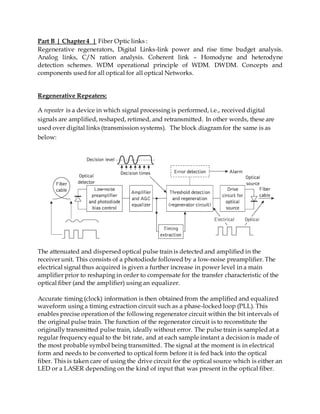
  • 1. Part B | Chapter 4 | Fiber Optic links : Regenerative regenerators, Digital Links-link power and rise time budget analysis. Analog links, C/N ration analysis. Coherent link – Homodyne and heterodyne detection schemes. WDM operational principle of WDM. DWDM. Concepts and components used for all optical for all optical Networks. Regenerative Repeaters: A repeater is a device in which signal processing is performed, i.e., received digital signals are amplified, reshaped, retimed, and retransmitted. In other words, these are used over digital links (transmission systems). The block diagram for the same is as below: The attenuated and dispersed optical pulse train is detected and amplified in the receiver unit. This consists of a photodiode followed by a low-noise preamplifier. The electrical signal thus acquired is given a further increase in power level in a main amplifier prior to reshaping in order to compensate for the transfer characteristic of the optical fiber (and the amplifier) using an equalizer. Accurate timing (clock) information is then obtained from the amplified and equalized waveform using a timing extraction circuit such as a phase-locked loop (PLL). This enables precise operation of the following regenerator circuit within the bit intervals of the original pulse train. The function of the regenerator circuit is to reconstitute the originally transmitted pulse train, ideally without error. The pulse train is sampled at a regular frequency equal to the bit rate, and at each sample instant a decision is made of the most probable symbol being transmitted. The signal at the moment is in electrical form and needs to be converted to optical form before it is fed back into the optical fiber. This is taken care of using the drive circuit for the optical source which is either an LED or a LASER depending on the kind of input that was present in the optical fiber.
  • 2. This is an advantage over the analog transmission systems where the concept of regenerative repeaters doesn’t exist. Digital Links – link power and rise time budget analysis : Solution is available in page no 323 to 331 Analog link Solution is available in page no 359 C/N Ration analysis Solution is available in page no 360 WDM optional principle is available in 4 sheet notes In fiber-optic communications, wavelength-division multiplexing (WDM) is a technology which multiplexes a number of optical carrier signals onto a single optical fiber by using different wavelengths (i.e., colors) of laser light. This technique enables bidirectionalcommunications over one strand of fiber, as well as multiplication of capacity. The term wavelength-division multiplexing is commonly applied to an optical carrier (which is typically described by its wavelength), whereas frequency-division multiplexing typically applies to a radio carrier (which is more often described by frequency). Sincewavelength and frequency are tied together through a simple directly
  • 3. inverse relationship, in which the product of frequency and wavelength equals c (the propagation speed of light), the two terms actually describe the same concept. A WDM system uses a multiplexer at the transmitter to join the signals together, and a demultiplexer at thereceiver to split them apart. With the right type of fiber it is possible to have a device that does both simultaneously, and can function as an optical add-drop multiplexer. The optical filtering devices used have conventionally been etalons (stable solid-state single-frequency Fabry–Pérot interferometers in the form of thin-film-coated optical glass). The concept was first published in 1978, and by 1980 WDM systems were being realized in the laboratory. The first WDM systems combined only two signals. Modern systems can handle up to 160 signals and can thus expand a basic 10 Gbit/s system over a single fiber pair to over 1.6 Tbit/s. WDM systems are popular with telecommunications companies because they allow them to expand the capacity of the network without laying more fiber. By using WDM and optical amplifiers, they can accommodate several generations of technology development in their optical infrastructure without having to overhaul the backbone network. Capacity of a given link can be expanded simply by upgrading the multiplexers and demultiplexers at each end. DWDM :
  • 4. Dense wavelength division multiplexing (DWDM) is a fiber-optic transmission technique that employs light wavelengths to transmit data parallel-by-bit or serial-by- character How does DWDM fair better : ► No O-E-O required ► Protocol & Bit Rate independence ► Increased overall capacity at much lower cost  Current fiber plant investment can be optimized by a factor of at least 32 ► Transparency  Physical layer architecture  supports both TDM and data formats such as ATM, Gigabit Ethernet, etc. ► Scalability  Utilize abundance of dark fibers in metropolitan areas and enterprise networks Coherent link-Homodyne and Heterodyne detection schemes: Coherent detection schemes are used in optical fiber communication as the direct detection schemes employed (PIN Photodetector) varies only with the intensity (Power) of the optical signal thus hindering the sensitivity and bandwidth capabilities of the detector. The onus in direct detection scheme was to consider only the power level of the optical signal ignoring the phase and frequency parameters by modulating the light intensity with the input electrical signal voltage. However in the coherent detection mode, the optical signal can be modulated based frequency, amplitude or phase improving the sensitivity of the detector and enhancing the bandwidth capabilities of the optical signal. This method along with the advantages brings to the fore the need to have tuned semiconductor laser to produce coherent output with as less spectral width as possible capable of being used in a single mode optical fiber, a proper coding (NRZ, RZ, Manchester) method for the data to be impressed upon the optical signal.
  • 5. Block of optical coherent system of modulation and detection scheme: In case of the modulation of the transmitting optical signal, the optical signal is modulated either by ASK, PSK or FSK. In direct detection scheme, the signal is amplitude modulated based on the electrical signal input which carries the information and hence the detection is proportional to the intensity of the optical signal. However in case of the coherent detection scheme, the incoming optical signal at the receiver end is mixed with a wave generated by a local oscillator and this is done before the detection by the photo-detectors take place and on the surface of the photo-detector. If the frequency of the signal carrier and that of the local oscillator is same, then the system is said to be a homodyne coherent detection scheme. Thus either the PSK or ASK can be used while transmission modulation is being taken care as FSK is ruled out here. Thus the output is a function of the intensities of the local oscillator wave and the source optical signal with the output taking the form, where the phase difference between source optical signal and that of the local oscillator is given by and Ps, Plo are the intensities of the signals. A sample block diagram for the homodyne coherent detection scheme is as below:
  • 6. The advantage of the homodyne scheme is that the output frequency is brought to the baseband level and no further electrical demodulation is necessary. Thus it is a highly sensitive detection system along with providing high bandwidth capabilities. However to manage the same frequency between the source and the local oscillator waves, it becomes a difficult requirement. Also since the phase of the two waves is locked, a requirement for the PLL is also necessary. If the frequency of the signal carrier and that of the local oscillator is different, then the system is said to be a heterodyne coherent detection scheme. Thus the phase difference between the source and local oscillator signal becomes important and the final output looks like this: . A sample block diagram of the heterodyne coherent detection scheme is as below:
  • 7. Though it doesn’t introduce the difficulty of having the systems to produce the same frequency for source and local oscillator signals, the sensitivity decreases and a -3Db degradation is introduced. Digital Links-link power and rise time budget analysis :
  • 9.
  • 11.
  • 12.
  • 15. Concepts and components used for all optical for all optical Networks. Available in page no 383 ► TTrraannssmmiittttiinngg SSiiddee  LLaasseerrss wwiitthh pprreecciissee ssttaabbllee wwaavveelleennggtthhss  OOppttiiccaall MMuullttiipplleexxeerrss ► OOnn tthhee LLiinnkk  OOppttiiccaall ffiibbeerr  OOppttiiccaall aammpplliiffiieerrss ► RReecceeiivviinngg SSiiddee  PPhhoottoo ddeetteeccttoorrss  OOppttiiccaall DDeemmuullttiipplleexxeerrss ► OOppttiiccaall aadddd//ddrroopp mmuullttiipplleexxeerrss