

Recommended
Recommended
More Related Content
Similar to pres.1993.2.3.203.pdf
Similar to pres.1993.2.3.203.pdf (20)
More from Mahamad Jawhar
More from Mahamad Jawhar (20)
Recently uploaded
Recently uploaded (20)
pres.1993.2.3.203.pdf
- 1. Robert N. Rohling and John M. Hollerbach Biorobotics Laboratory McGill University Montreal, Quebec, Canada H3A 2B4 Stephen C. Jacobsen Center for Engineering Design University of Utah Salt Lake City, Utah 841 12 Optimized Fingertip Mapping: A General Algorithm for Robotic Hand Teleoperation Abstract An optimized fingertip mapping (OFM) algorithm has been developed to transform hu- man hand poses into robot hand poses. It has been implemented to teleoperate the Utah/MIT Dextrous Hand by a new hand master: the Utah Dextrous Hand Master. The keystone ofthe algorithm is the mapping of both the human fingertip positions and orientations to the robot fingers. Robot hand poses are generated by minimizing the errors between desired human fingertip positions and orientations and possible robot fingertip positions and orientations. Differences in the fingertip workspaces that arise from kinematic dissimilarities between the human and robot hands are accounted for by the use of a priority based mapping strategy. The OFM gives first priority to the human fingertip position goals and the second to orientation. Introduction PRESENCE, Vol. 2. No. 3. Summer 1993. 203-220 © / 994 The Massachusetts Institute of Technology Hand masters are being developed and applied for teleoperation of mul- tifingered robot hands, control ofgraphics displays, and interfaces for computer games (Eglowstein, 1990; Foley, 1987). Popular commercial hand masters include the VPL DataGlove (VPL Research Inc., Redwood City, CA), the Exos Dextrous Hand Master (Marcus, Lucas, & Churchill, 1989), and the Cy- berGlove (Virtual Technologies, Stanford, CA). For more advanced applica- tions, force-reflecting hand masters have been developed, including a hydraulic- powered system (Jacobsen, Iversen, Davis, Potter, & McLain, 1990), electric drive systems (Iwata, 1990; Jau, 1992; Oomichi, Miyatake, Maekawa, & Haya- shi, 1988), and pneumatic-powered systems (Burdea, Zhuang, Roskos, Silver, &Langrana, 1992; Stone, 1991). For some of the telemanipulator systems just cited, the hand master and the robot hand have the same geometry, and so the kinematic mapping is direct. Human finger motion is restricted to that allowed by the master's kinematics. For other systems, there may be significant geometric differences between ro- bot and hand master, especially for those hand masters that attempt to measure directly the human finger joint angles. Direct measurement of the human joint angles requires a model of the human hand kinematics to be derived when implementing a teleoperation algorithm. Teleoperation of dextrous robot hands then requires an algorithm that performs transformations of human hand poses to the robot hand. This paper describes an optimized fingertip mapping (OFM), which ad- dresses kinematic dissimilarity via a goal priority approach to fingertip control. Rohling et al 203 Downloaded from http://direct.mit.edu/pvar/article-pdf/2/3/203/1622527/pres.1993.2.3.203.pdf by guest on 12 April 2021
- 2. 204 PRESENCE: VOLUME 2, NUMBER 3 Figure I. Utah/MIT Dextrous Hand. The OFM has been implemented to teleoperate the Utah/MIT Dextrous Hand by a new hand master, the Utah Dextrous Hand Master. 2 Utah/MIT Dextrous Hand The robot hand (Fig. 1) is a four fingered tendon operated hand; it is similar in size to a human hand and contains one finger (thumb) to oppose the other fingers (Jacobsen, Iversen, Knutti, Johnson, & Biggers, 1986). Figure 2 shows the overall kinematic structure ofthe robot hand. A Denavit-Hartenberg (DH) coordinate system (Denavit & Hartenberg, 1955 or Paul, 1981) has been established to describe the kinematics of each finger ofthe robot hand. Reference frames are also placed at each fingertip, therefore the last DH parameters locate the fingertip. The DH coordinate systems are depicted in Figure 3 and the DH parameters are located in Table 1. Common Reference Frame Finger 1 Finger 0 Figure 2. Kinematic model ofthe Utah/MIT Dextrous Hand. The model is shown in the zero-angle position. The common reference frame is located at joint 2 offinger 2. This paper adopts the following notation to identify joints and coordinate systems: • joint ij (i = 0, 1, 2, 3 j = 1, 2, 3,4) refers to finger i, joint ;' Downloaded from http://direct.mit.edu/pvar/article-pdf/2/3/203/1622527/pres.1993.2.3.203.pdf by guest on 12 April 2021
- 3. Rohling et al 205 Äooi y0 |z0Zoo «T*- Yc r-vz, 02 L20 ^03 y—fZo4 -'04 v02 x03 04 X30T Z30 y3o Palm View Side View of Palm Figure 3. Coordinate description ofUtah/MIT Dextrous Hand shown with fully extended fingers. Dashed lines indicate vectors not lying in plane ofpage. Denovit-Hartenberg parameters ofVector,¡ (finger i, joint j) are found in Table I. • coordinate system ik (i = 0, 1, 2, 3 k = 0, 1, 2, 3, 4 k = j — 1) refers to coordinate system axes labeled ik. The labeling of coordinate systems k =j — 1 cor- responds to the standard Denavit-Hartenberg con- vention of labeling joint axes/ — 1 at joint/. An axis system is also placed at the fingertip and corresponds to k = 4. • The base coordinate frame is labeled simply as sys- tem 0. A remote pneumatic actuator pack activates each fin- ger joint movement via antagonistic tendons. Control is provided by the CONDOR (Narasimhan, Siegal, & Hollerbach, 1989) real-time control system by using joint angle data and tendon tension data from Hall-effect and strain-gauge sensors respectively. The wrist of the robot hand is attached with a fixed palmar orientation to a 3-DOF Cartesian robot. The Cartesian robot follows the human operator's wrist mo- tion through the use of a Bird position sensor (Ascen- sion Technology Corp., Burlington, VT). The Bird sys- Table I. Denavlt-hfartenberg Parameters for the Utah/MIT Dextrous Hand j a,}(mm) si} (mm) ot,; (deg) 6,y (deg) Finger/ = 1,2,3 0 -18.0 1 2 3 4 15.2 43.2 33.0 18.7 Finger i - 0 0 1 2 3 4 0 10.2 43.2 33.0 18.7 -17.7» 18.4 50.7 -53.6 0 0 0 0 0 0 0 0 90 90 0 0 0 90 -90 0 0 0 12 [-45,45]* [-60,30] [0,90] [0,90] 0 [-45,45] [-14,54] [4,90] [0,90] aho^20,s30, respectively. bA variable range. Row/ = 0 corresponds to the transformation between coordinate system 0 and system ¿0. tern consists of a small electromagnetic receiver strapped to the operator's wrist and a remotely mounted trans- mitter. 3 Utah Dextrous Hand Master The hand master (Fig. 4) measures motion of the thumb, index, middle, and ring fingers, via a carbon- fiber exoskeleton attached to an elasticized glove. The exoskeleton is comprised of three pairs of parallel-link mechanisms spanning the length of each finger and at- tached to an immobile base on the back of the hand. Pads are adhered to the glove surface above the three finger links of each finger and connected to the parallel linkages. Rotation of adjacent pads or rotation of the proximal pad with respect to the immobile base yields an angular motion between pairs of parallel linkages (Fig. 5) and is measured by Hall-effect sensors. Abduction- adduction of each finger rotates the series of parallel link- Downloaded from http://direct.mit.edu/pvar/article-pdf/2/3/203/1622527/pres.1993.2.3.203.pdf by guest on 12 April 2021
- 4. 206 PRESENCE: VOLUME 2, NUMBER 3 Figure 4. Utah Dextrous Hand Master. ages about the perpendicular axis ofjoint 1 and is mea- sured by Hall-effect sensors located in the base. The first hand master, created by Ed Iversen and Steve Jacobsen at the University of Utah, employed a straight linkage design in the exoskeleton and used Hall-effect joint angle sensors. This design was later modified and marketed as the EXOS Dextrous Hand Master. This first design had the drawback of not measuring the finger joint angles accurately, because of the kinematic mis- match between the exoskeleton joints and the human finger joints. This mismatch would also require the exo- skeleton attachments to move during finger flexion. The first design gave readings, which were also sensitive to how the glove was put on, because of a translation de- pendence of the attachment points. That is to say, the readings depended on the exact location ofthe attach- ment bands on each finger segment. To avoid this mismatch, the Utah Dextrous Hand Master employs four bar linkage connections between joints and measures the angle between the pads contact- ing the human finger segments. If the pads are well ad- hered to the finger segments and the soft tissue under the pads undergoes negligible deformation, the finger joint angles are accurately measured. The Utah Dextrous Hand Master is also translation invariant: the exact loca- tion of the pads on the finger segments does not affect the readings. Compared to the VPL Dataglove, an exo- skeleton based hand master design offers the advantage that the joints angles may be measured independently. 4 Previous Hand Teleoperation Algorithms The VPL DataGlove and the EXOS Dextrous Hand Master have been previously employed to operate the Utah/MIT Dextrous Hand. Mappings developed for the VPL Dataglove and EXOS Hand Master include (1) linear joint angle mapping (Hong & Tan, 1989), (2) pose mapping (Pao & Speeter, 1989), and (3) fingertip position mapping (Speeter, 1992). These algorithms Downloaded from http://direct.mit.edu/pvar/article-pdf/2/3/203/1622527/pres.1993.2.3.203.pdf by guest on 12 April 2021
- 5. Rohling et al 207 Figure 5. Utah Dextrous Hand Master kinematics. Hall-effect sensors are placed at each joint angle label in the top figure. were implemented with the Utah Dextrous Hand Mas- ter to determine their ability to successfully teleoperate the Utah/MIT Dextrous Hand. 4.1 Linear Joint Angle Mapping Linear joint angle mapping is possible because the robot hand and the hand master both contain four fin- gers with four joints per finger. The intrinsic assumption here is that the kinematics ofthe robot and human hands are nearly identical. The fingers of the robot hand each have three parallel rotary joints and a perpendicular rotary base joint connecting the fingers to the palm base. This structure is roughly equivalent to the human finger joints. Yet there are significant kinematic dissimilarities, such as the direction and location ofthe finger base joints as well as link length differences. Despite the kine- matic differences, the 16 joint angles of the hand master each has a corresponding joint on the robot hand and a linear function relating the robot hand and hand master joints may be established: e^obot = mt}^" + bg where 9(y°bot is the angle of finger ¿, joint/ ofthe robot hand, 9"™"" is the angle offinger i, joint/ of the hand master, and w,y and by are constants determined by com- parison of the kinematics and trial and error during implementation. This simple mapping generated roughly similar hu- man and robot motions, but was unsatisfactory because the kinematic dissimilarities between the human and robot hands required the operator to make contorted hand poses to achieve the desired robot hand motions. 4.2 Pose Mapping Algorithm We also tested pose mapping, where the robot and human hand were placed in a number of similar poses and a relationship between each robot angle and a sum of 16 weighted hand master joint angles was found by a least-squares fit. This relationship was found by manu- ally manipulating the robot hand into a pose that mimics the pose that the human operator was assuming. The hand master joint angles and the robot joint angles were then recorded. This was repeated for n poses and may be put in matrix form: AT = B where A is a matrix of measured human hand poses of dimension n by 16 (number of measured hand master angles), T is the 16 by 16 transformation matrix be- tween hand master and robot joint angles, and B is a Downloaded from http://direct.mit.edu/pvar/article-pdf/2/3/203/1622527/pres.1993.2.3.203.pdf by guest on 12 April 2021
- 6. 208 PRESENCE: VOLUME 2, NUMBER 3 matrix ofmeasured robot hand poses ofdimension n by 16 (number ofjoints of robot hand). The T matrix was found through pseudoinversion techniques after n = 20 poses were measured. The robot joint angles may therefore be calculated from the trans- formation of the hand master joint angles: tlT = £ where n is a row vector of hand master joint angles and £, is a row vector of robot joint angles. This method was also computationally simple but suf- fered from a lack ofoperator confidence in controlling the robot hand, particularly for delicate tasks where pre- dictability is important. The relationship between robot and human joint angles determined this way appears unpredictable to the operator because movement ofonly one human joint results in motion ofmany of the robot joint angles. Modifying the algorithm to calculate each robot joint angle from a weighted sum ofonly the four joints of the corresponding human finger resulted in little improvement. Further drawbacks include the need to perform these pose mappings for each new operator and a lack of a clear definition ofwhat identical poses are for kinematically dissimilar hands. 4.3 Synergistic Fingertip Mapping Algorithm Finally, we tested a simple version offingertip po- sition mapping, which did not address fingertip orienta- tion, workspace differences, or make use of the robot redundancy of fingertip position. The human fingertip positions were calculated using a simple model ofthe human hand and the measured hand master joint angles. Using a common reference frame located in the palm, the inverse kinematics ofthe robot hand were solved and implemented whenever the solutions were within the joint limits. To resolve the fingertip position redun- dancy, the algorithm simply set the angle ofjoint 3 equal to the joint 4 angle for each finger: 6¿3obot = ö,i4bot * = 0, 1> 2, 3 This synergistic relationship is reasonable for free human finger motion. The operator felt more comfortable during telema- nipulation than with previous mappings, as direct con- trol of the distance between fingertips appears to be es- sential for performance ofgrasping tasks. Yet problems were encountered similar to those discussed in previous research (Speeter, 1992): • Human-robot kinematic dissimilarities result in only a partial overlap of the fingertip workspaces. • Errors are introduced by approximations of a sim- plified model ofthe human hand and inaccuracy of the hand master measurements. • Each robot finger contains fewer than 6 degrees of freedom (DOFs) to track the mapped human posi- tion and orientation. In response to these problems we developed the Opti- mized Fingertip Mapping (OFM), which differs from previous work by (1) matching fingertip orientation as well as Cartesian position, and (2) generating robot poses when exact mapping is not possible due to work- space dissimilarities. OFM minimizes the human-robot fingertip position and orientation error within the con- straints ofeach robot finger's workspace and available DOFs. A priority scheme is implemented that favors position over orientation. At present the OFM algorithm has been implemented only on the Utah/MIT Dextrous Hand and Utah Dex- trous Hand Master master/slave combination. The OFM idea may be applied, however, to any combina- tions ofhand masters/slaves that have the same number offingers. 5 Human Hand Model The Utah Dextrous Hand Master contains a large number of sensors that allow a sophisticated model of the human hand to be used for OFM human fingertip calculations. The hand may be considered (Chao, An, Cooney, & Linscheid, 1989) as a linkage system of articulated bony segments. These segments define the fingers and the palm and allow motion through movement between bone segments. Joint motion is produced by muscle Downloaded from http://direct.mit.edu/pvar/article-pdf/2/3/203/1622527/pres.1993.2.3.203.pdf by guest on 12 April 2021
- 7. Rohling et al 209 Index.Middle,Ring Finger io^ x {¿¡3 i ¿12 Un y¡3 y¡2 DIP PIP Thumb Z03 1Z, ym MP 00. |Zo3 |Z02 1Z01 X03 ^ ><02,. X01 I d01 01 ^ - 'M>, 00 y00 yo3 yo2 y.01 MCP TMC Figure 6. Side view ofhuman finger model. Alljoints are assumed to rotate about fixed axes. forces and constrained by both soft tissue (including muscle and capsuloligamentous structure) and bone seg- ment shape. These constraints allow simplifications to be made about gross finger motion. Human hand kinematic studies (Cooney, Lucca, Chao, 8c Linscheid, 1981; Thompson & Giurintano, 1989) show at least 5 DOFs for each finger. A simplified model is dictated by the 16 DOFs of the hand master. The simplified model first approximates each joint as a rotation about a fixed axis. The distal interphalangeal (DIP) and proximal interphalangeal (PIP) joints ofthe index, middle, and ring fingers, and the interphalangeal (IP) and metacarpophalangeal (MCP) joints of the thumb are assumed to have 1 DOF (Fig. 6). The meta- carpal (MP) joint of the index, middle, and ring fingers, and the trapeziometacarpal (TMC) joint of the thumb are assumed to have 2 DOFs. Flexion extension ofthe MP and TMC joints is assumed to be about an axis lo- cated at the MP and TMC joints and parallel to the distal joint axes. The ¿0 coordinate system ofthe hand master (the co- ordinate system located at the exoskeleton insertion point into the base) is not coincident with the MP and Table 2. Human Parameters (ofRNR) ofthe Simplified Human Hand Model: /, = Human Finger Link Length, ,0d,, = Vector from Coordinate System ¡0 to i I (mm) Finger i 0 12 3 4 'Mi 50.8 31.7 25.4 12.7 0 -38.1 45.7 30.5 19.0 33.0 0 -40.6 50.8 31.7 19.0 34.9 0 33.0 45.7 30.5 19.0 28.6 0 -30.5 y Zio 'At*0 10 A20 X3C Master Base ~ x 00 Zoo *y00 Figure 7. Back view ofthe insertion points of each finger into the hand master base. Dashed lines indicate vectors not lying in the plane ofthe page. TMC joints, but is displaced by vector ,0d,i (Fig. 6) and is located a short distance above the middle of the back ofthe hand. Thus abduction-adduction is only approxi- mately measured by rotation about z,0, and this approxi- mation is incorporated into the simplified model. The simplified model is therefore comprised ofboth human parameters and hand master parameters. The human parameters describe the finger link lengths and the translation between coordinate systems ¿0 and ¿1 (Table 2). The hand master parameters describe the transformations between each of the ¿0 coordinate sys- tems (Fig. 7 and Table 3). Downloaded from http://direct.mit.edu/pvar/article-pdf/2/3/203/1622527/pres.1993.2.3.203.pdf by guest on 12 April 2021
- 8. 210 PRESENCE: VOLUME 2, NUMBER 3 Table 3. Hand Master Parameters ofthe Simplified Human Hand Model0 Finger i 20R,o 0.766 0.260 -0.601 1 0 0 1 0 0 -0.434 -0.485 -0.765 0 0.981 -0.196 0 0.981 0.196 -0.488 0.840 -0.255 0 0.196 0.981 0 -0.196 0.981 20, d» -56.3 42.7 -57.5 0 28.8 -2.5 0 -28.8 -2.5 transformations of each ¿0 coordinate system are represented with respect to the 20 coordinate system. 20R,o = rotation matrix describing coordinate system 20 with respect to ¿0. 20d¿0 = vector from coordinate system 20 to¿0 (mm). 120 100 80 60 40 20 0 -20 -40 -60 Common Reference Frame Origin dashedline = humMfingertip workspace solid line = robot fingertip workspace -50 0 50 x tip position (mm) 100 Figure 8. Workspace boundaries for robot finger 2 forjoint 21=0° and for human finger 2 forjoint 21 = 0°. Both fingers are shown with respect to the common reference frames. Amplified Hall-effect sensor voltages from the hand master are read through an A/D converter by CON- DOR. Resolution of the measured angles is ±0.1° on average, and is limited by Hall-effect sensor noise. All Hall-effect sensors and linkages have an angular range of 90° to measure unobtrusively almost the entire range of human joint motions. Located on the backside of the hand, the exoskeleton partially inhibits finger crossing but does not inhibit hand motion for most tasks. 6 Human-Robot Kinematic Differences The most important kinematic differences between the human hand model and the robot hand are the struc- ture of the finger base joints and the location of the thumb. The robot finger base joints 1 lie at an angle tilted 30° above the palmar plane. The human model joint 1 lies nearly perpendicular to the palm. The differ- ence in the orientation of these axes results in a differ- ence in the abduction-adduction motion of the robot and human fingers. The robot fingers abduct-adduct in a rolling motion with respect to the palm whereas the hu- man fingers abduct-adduct in a yaw motion with respect to the palm. The robot thumb is located in the palm equidistant from fingers 1 and 2. The human thumb is located along axis z0o of the simplified model, which intersects the palm near the TMC joint at the edge of the palm. Fur- thermore, the orientation ofthe base joint of the robot thumb lies parallel to the palm whereas the human thumb rotates about a joint axis at approximately 45° to the palm. All four of the robot fingers have equal total finger lengths. Human finger lengths exhibit a length variance among fingers that depends on each person. Most com- monly, total finger length decreases from thumb to middle finger to approximately equal index and ring fin- gers. The combined kinematic differences result in different fingertip workspaces. Figure 8 shows the difference in a planar section ofthe workspace that arises from the kine- matic dissimilarity of the middle fingers (using one of the author's (RNR) middle finger). The workspaces in Downloaded from http://direct.mit.edu/pvar/article-pdf/2/3/203/1622527/pres.1993.2.3.203.pdf by guest on 12 April 2021
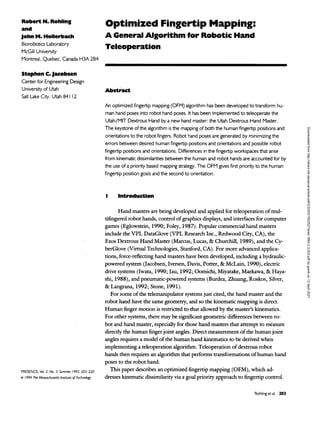
- 9. Rohlingetal 211 Human Fingertip Colculotlons Kead joint angles from master glove and calculate forward kinematics of fingers ¡-0.1,2,3 Express each finger's position and orientation w.r.t. common reference frame Robot Finger Joint Calculations Find finger 2 joint 1 angle" Express finger ¡=0,1,2,3 position and orientation w.r.t. system Î0 I Find finger ¡=0,1,3 joint 1 angle Solve Planar Finger Problem For finger 1=0,1,2,3 express positior and orientation w.r.t. system i1 Extract [xta»yd«.] from position and 4frw from orientation_ Branch 1 Attempt to match [xd( within joint limits •yd«.] ond *<!< Unsuccessful Branch 2 Attempt to match[xdM,ydet] within joint limits Unsuccessful Successful Branch 3 Place robot fingertip position where error from [xd--,yd„jl ¡e minimized and is within joint limits Successful If more than one solution is found then choose solution whose orientation is closest to 4> ^ Successful Implement calculated joint angles on robot hand_ Figure 9. OFM algorithm. The three branches are shown. Figure 8 overlap well because the robot and human fin- gers have almost equal total lengths. The robot fingers 1 and 3 have a smaller intersection ofworkspace volume with human fingers 1 and 3 because of a greater differ- ence in finger lengths. The workspace intersection of the thumbs is very small because of the large relative posi- tion difference of base joint locations and the difference in thumb link lengths. 7 Optimized Fingertip Mapping OFM proceeds by (1) calculating the forward kine- matics of the human hand, (2) mapping the fingertip positions and orientations to the robot hand via a com- mon reference frame, and (3) generating robot inverse kinematic solutions. For human hand poses where fin- gertip position and orientation mapping are not pos- sible, approximate solutions must be generated without introducing discontinuities between exact and approxi- mate mapping. The OFM algorithm continuously gen- erates exact and approximate fingertip poses throughout the robot workspace by prioritizing the position and orientation goals and minimizing the errors. The algo- rithm is shown in Figure 9. 7.1 Forward Kinematics The forward kinematics are calculated from hand master joint angle data using the simplified human hand Downloaded from http://direct.mit.edu/pvar/article-pdf/2/3/203/1622527/pres.1993.2.3.203.pdf by guest on 12 April 2021
- 10. 212 PRESENCE: VOLUME 2, NUMBER 3 model. First the forward kinematics of each finger are calculated with respect to coordinate system ¿0. 'l22 COS GST" + ¿23 COS (%%"" + *T")' + i2i cos (esf^ + e5fter + 92n4astcr) 0 l22 sin 8¡T" + l23 sin (Q?rKr + eg"") _i_ / «¿m /û master _i_ a master _i_ omasterx + ¿24 sin (ü22 + H23 + H24 ) ilYhuman _ /0Yhuman iO"D human .Inhuman + ,0^ R v,n(e« master . a master _i_ omaster 2 + ö,3 + ö<4 ) where '¿xi111™11 is the human fingertip position vector with respect to coordinate system ik, <*R^uman is the 3-by-3 human fingertip orientation matrix; it represents X-T-Z fixed angle rotations about the coordinate sys- tem ik, lij is the human finger link length, 9,y,astcr is the hand master joint angle, RV/i(9) is the 3-by-3 rotation matrix describing a rotation 9 about ylh, and ,0d¿i is the vector from coordinate system ¿0 to ¿1. The forward ki- nematics of each finger is completed by including abduc- tion-adduction, which consists of a rotation ofthe fin- gertip position and orientation vectors about the axis z,0. baseurhuman _ n /amaster i'0vhuman base<T> human R /û master ¿Ou human zi0 (Ö«I ) K> where base chuman and baselRhuman are thc fingertip posi. tions and orientations after abduction-adduction. 7.2 Scaling of Human Hand Parameters Scaling of the human hand model parameters dur- ing forward kinematics calculations to more closely match the robot parameters was investigated to address the fact that human hand sizes vary significantly. Hands of different sizes placed in the same type of pose produce slightly different robot hand poses if a scale factor is not used. A scaling factor was introduced to scale the human hand to have the same average finger length as the robot fingers. The scaling factor did make the robot attain poses that were more aesthetically similar to the human poses and did not depend on human hand size. 7.3 Common Reference Frame Mapping fingertip positions and orientations re- quires a common reference frame on the human and ro- bot hands. Previous fingertip mapping research (Hong &Tan, 1989; Speeter, 1992) placed the common ori- gins at the base of the thumbs. The base ofthe thumb is not a good location for the common reference frame between the robot hand and the human hand for finger- tip mapping. The kinematic differences previously cited result in a very small overlap ofthe robot and human workspaces because the thumbs are the most kinemati- cally dissimilar fingers of the robot and human hands. Furthermore, the human thumb base is difficult to locate because of a lack of bony landmarks. The OFM algo- rithm uses common reference frames located at the MP joint of the middle human finger and joint 2 of the robot finger 2. These locations were chosen because they lie at locations of high kinematic similarity. Specifically, the human reference frame is located at the middle of the MP joint ofthe middle finger oriented along the finger. The position and orientation of each human finger are transformed to the common origin MP by first transforming from coordinate system ¿0 to 20, then transforming to MP by a rotation of - 9™ster about z20 and translation by — 20d2i. MP „human = RZ2o(-Q^ri[20R,0b-'x,human + 20d,0] - 20d21 MP T> human _ 1} / a master 20"D baseiü human The robot reference frame is located at joint 2 offin- ger 2, rotated 60° from the 21 coordinate system (Fig. 2) so that it points along the finger similar to the human reference frame. The mapped position and orientation of each robot finger with respect to coordinate system 21 are therefore 21« robot _ = Rz„ (-60°) ,° MPvhuman 21t> robot _ Rz„ (-60°)MPR o MPtj human In other words, the human fingertip positions and orientations that were written with respect to the immo- bile base are first transformed to the common reference frame pointing along the human middle finger with an origin at the MP joint. This is then the desired position Downloaded from http://direct.mit.edu/pvar/article-pdf/2/3/203/1622527/pres.1993.2.3.203.pdf by guest on 12 April 2021
- 11. Rohlingetal 213 and orientation for the robot hand with respect to a similar reference frame located at joint 2 of finger 2 pointing along the robot finger. The nearest robot DH coordinate system is system 21 so the desired robot posi- tion and orientation are then expressed with respect to system 21 by rotating by 60°. 7.4 Inverse Kinematics The OFM algorithm inverse kinematics consider the desired fingertip position 21x!robot as the first priority goal, and fingertip orientation 21Rfobot as the second pri- ority goal. 7.4.1 Simulations of Planar Finger Motion. Ini- tially simulations of planar finger movement were per- formed by two implementations of the goal prioritiza- tion method. The first simulations were composed in the velocity domain (Nakamura, Hanafusa, & Yoshikawa, 1987) where Jacobian matrices were written to describe each goal and inverse kinematics performed through pseudoinversion techniques. While easy to formulate, the drawbacks to this ap- proach include being computationally intensive. A fast servo rate between human and robot motion is necessary during teleoperation. It is also difficult to incorporate joint limits. Furthermore, for large differences in robot- human hand positions, such as during start-up, the solu- tion will "overshoot" before settling down. There are other inverse kinematics strategies to do redundancy resolution (such as Pohl & Lipkin, 1990), but it was found that solutions could be found directly by a geometric analysis. The geometric analysis can be performed at considerably lower computational cost and yields robot joint angle solutions without derivatives. It encompasses joint limits in the priority scheme and cal- culates the optimum robot pose in one step. A second set of simulations verified the practicality of the geomet- ric analysis approach (Fig. 10). 7.4.2 Optimized Fingertip Mapping. Each robot finger is redundant with respect to fingertip position. For a given robot fingertip position, orientation is fixed except within the plane determined by the three parallel 100 r 50 Oh -50 Robot Workspace Boundary Branch 3 Branch 1 Branch 2 Branch 3 Branch 2 + Desired Trajectory Position o Actual Robot Fingertip Position -50 0 50 x tip position (mm) 100 Figure 10. Simulation ofa robot finger tracking a linear trajectory within its plane with a desired orientation of 185°. All three branches of the OFM tree are traversed during tracking. Table 4. OFM Structure 1 Achieve desired position and projected orientation 2 Achieve desired position and minimum error from projected orientation 3 Achieve minimum error from desired position distal joints. The desired robot orientation is therefore the projection of the human orientation into the plane of the robot finger. The goal prioritization results in a three branched algorithm for each fingertip (Table 4). The solution will fall into one of these three categories with highest priority on the first category. OFM Joint Angle Calculations. A three-dimen- sional drawing of a projected position into the plane of the finger (Fig. 11) may be useful as a reference when following the detailed OFM calculations. 1. The common robot reference frame, as previously described, is attached to joint 2 of finger 2. Joint 1 Downloaded from http://direct.mit.edu/pvar/article-pdf/2/3/203/1622527/pres.1993.2.3.203.pdf by guest on 12 April 2021
- 12. 214 PRESENCE: VOLUME 2, NUMBER 3 Palm Base Plane of Finger ''Rotation Axis -Desired Position, Orientation -Projected Position, Orientation Fingertip Workspace Boundary Figure II. Projection ofdesired fingertip position and orientation onto the plane offinger I. Joint I of finger I is shown rotated to the limit of —45°. This situation corresponds to item 3a or 3b in the Summary ofOFM Calculations and the Criteria for Success. offinger 2 cannot therefore be calculated from po- sition or orientation data. Joint 1 offinger 2 is cal- culated by equating the distance swept out by the human base joint movement from its middle posi- tion to the distance swept out by the robot base joint movement from its middle position. e™bot = r/22 cos e^*" +1 >2 s~rxc /Qmastcr _i_ «master 23 COS (922 + ö23 _i_ / ^^r. /omaster _i_ Amaster _i_ omastem + *24 cos ("22 + H23 + ö24 )J x 92n1astcr/[21^obot + J21] This angle is clipped to be within the joint limits of ±45°. If the common reference frame was located at a fixed position in the palm, joint 1 of all fingers could be determined from fingertip position data. The fingertip position and orientation with respect to the base would then be slightly different than the OFM method. The fingertip position and ori- entation with respect to each other, however, are identical. The OFM common reference frame placement, as previously described, has the advan- tage of lying at a location ofhigh kinematic simi- larity and therefore has a large overlap of the hu- man and robot finger workspaces. 2. The position and orientation of fingers 0, 1, and 3 are transformed from coordinate system 21 to each finger base ¿0: iOvrobot „„.„„„. _ >(m 21vrobot i iOJ X¿ — JV2i X,- -r Q2i iOji robot _ ¿0"D 21TJ robot R2i21Rf 3. The joint 1 angle for fingers 0, 1, and 3 is calcu- lated from desired position data: 9,rS>bot = atan2(!'°yirobot, «»j^*«) The angle is clipped to within the joint limits of ±45°. The joint 1 angle determines the plane of each finger. 4. The position and orientation are transformed into the plane of the finger. ¿l-v-robot _ ¡I'D ¿O-v-robot i il J robot ¿iRfbot = ''1R.0'0R,r The remaining jointsj = 2, 3, 4 for fingers i = 0, 1, 2, 3 form a three-link planar problem with re- spect to each coordinate system »1. The three-link planar problem is solved using the x,y elements of liebelt as t^e desired position and the desired ori- entation cpdes is extracted from !lRir°b°t- The z ele- ment of '1xJrobot will equal zero if the joint 1 angle has not been clipped. Ifjoint 1 has been clipped, thcx,y elements of ,1xIrobot represent the projection of ,0-iç:ohoc onto the plane of the finger. The desired fingertip position is labeled [x^, ydcs]. 4a. Calculate an inverse kinematic solution to the Downloaded from http://direct.mit.edu/pvar/article-pdf/2/3/203/1622527/pres.1993.2.3.203.pdf by guest on 12 April 2021
- 13. Rohlingetal 215 3-link planar problem using both the desired po- sition and orientation. 9™bot = acos [(4, + yis - a22 - a2,)/(2a,2al3)] atan2(ydes, x^) + atan2 (ai3 sin 9£bot, a,2 + al3 cos 9,r3obot) 9robot _ a - 6robot _ ± a robot ¿4 _ «Pdes " ö(3 6robot a The solution is successful if 9$**, 9£bot, and 9£bot are within the joint limits as found in Table 1. 4b. If solution 4a cannot be found within the joint limits calculate an inverse kinematic solution that achieves desired position and minimizes orienta- tion error. This entails placing one ofthe joints at one of its limits and solving for the other two joint angles to achieve the desired position. This procedure is repeated for all three joints at both ofeach joint's limits for a total ofsix possible pose solutions. An example ofthe equations for one of the six calculated poses is given below and is shown in Figure 12. The other equations are easily derived in a similar manner. a robot __ = 0 (joint limit) «robot _ acos xL + Ydes - «a - («¿s + *rt): 9robot _ a - 2a,2(ai3 + ai4) atan2(ydes, x^) + atan2 [(ai3 + ai4) sin 9£bot, + (al3 + ati) cos 9£bot] 6robot n ¿3 ~ °<2 robot I _. _ ii Arobot e - I <Pdes _ "¡4 The solution is successful if 9£bot, 9;3obot, and 9J°bot are within the joint limits. Ifmore than one pose is successful, the solution chosen is the one that obtains the minimum orientation error e. 4c. Ifsolution 4b cannot be found within the joint limits then calculate an inverse kinematic solution minimizing the error between the robot fingertip L^les^des J Figure 12. One ofsix possible finger poses when one joint angle is set to a limit. 0 50 x tip position (mm) Figure 13. The region outside the workspace boundary for fingers 1,2, and 3 is segmented into six regions. Vertices are labeled A, B, C, and D. and the desired position. The area outside the workspace is divided into separate regions (Figs. 13 and 14). Equations are written for each region that determine the location along the workspace boundary that minimizes the position error from the desired position. First each defined region is checked to determine ifthe region contains the desired position and the fingertip is placed at the Downloaded from http://direct.mit.edu/pvar/article-pdf/2/3/203/1622527/pres.1993.2.3.203.pdf by guest on 12 April 2021
- 14. 216 PRESENCE: VOLUME 2, NUMBER 3 -50 0 50 100 x tip position (mm) Figure 14. The region outside the workspace boundary for the thumb is segmented into six regions. Vertices are labeled A, B, C, and D. position of minimum distance error. The mini- mum distance error occurs when the robot is placed at the workspace boundary whose perpen- dicular intersects [x^, ydes]. As an example of the finger 1 calculations, the equations representing region 1 of Figure 13 are: criteria for position within region 1 : [Xdes + (Ydes - 0,2)2] > («i3 + ^ Xdcs < 0 and ydes > ai2 ifcriteria is satisfied: erobot = 90o 9;30bot = atan2(|xdes|,ydes-«l2) 9£bot = 0 Equations of region determination and joint angle solutions are easily derived in a similar man- ner for the other regions. Regions are defined only for the sections that have a smooth work- space boundary. When the [x^,, ydes] is nearest to a vertex of the workspace boundary a separate calculation must be made. If [x¿es, ydes] is not found in one of the six described regions then the robot fingertip is placed at the vertex closest to [xdes, ydcs]. The closest vertex is found by calculat- ing the distances to each vertex A, B, C, and D. Great care must be taken to ensure continuity of the joint angle solutions when changing branches. The opti- mizing nature of the branches produces continuity of the robot joint angles but the continuity may be lost if for example orientation jumps from —10° to 350° because of a change oftrigonometric equations between branches. Standardizing the orientation range reduces the possibility of introducing program-generated discon- tinuities. The OFM algorithm contains the goal priority gener- ated branches within the solution of the planar finger problem—after the joint 1 angle has been calculated. Success in branch 1 of achieving the desired projected position and orientation in the plane does not indicate that the desired position is necessarily matched in three- space unless joint 1 has not been clipped to its joint limit. The three-branched OFM structure contains three subbranches from branch 3. The subbranches arise when fingertip position is not achievable because of the joint 1 range limit but redundancy ofjoints 2, 3, and 4 still al- lows orientation consideration within the plane ofthe finger. Summary ofOFM Calculations and the Criteriafor Success 1. Achieve desired position and projected orienta- tion: a. joint 1 calculation lies within joint range and b. position and projected orientation within finger plane are achievable within joints 2, 3, and 4 ranges. 2. Achieve desired position and minimum error from projected orientation: a. joint 1 calculation lies within joint range and b. position within finger plane is achievable and errors from projected orientation are minimized within ranges ofjoints 2, 3, and 4. Downloaded from http://direct.mit.edu/pvar/article-pdf/2/3/203/1622527/pres.1993.2.3.203.pdf by guest on 12 April 2021
- 15. Rohling et al 217 Figure 15. Teleoperation ofthe Utah/MIT Dextrous Hand with the Utah Dextrous Hand Master in conjunction with the Bird position sensor and the wrist positioning robot. 3. Achieve minimum error from desired position: i. projected orientation is achievable: a. joint 1 is clipped to a joint limit b. both projected position and projected orien- tation within finger plane are achievable within ranges ofjoints 2, 3, and 4. ii. closest to projected orientation: a. joint 1 is clipped to a joint limit b. projected position is achievable and error from projected orientation within finger plane is minimized within ranges ofjoints 2, 3, and 4. iii. no orientation consideration: position lies out- side finger workspace: a. always successful by placing fingertip at workspace boundary. For any given continuous trajectory of desired posi- tions and orientations the OFM algorithm generates a continuous robot trajectory. It can be easily shown that the algorithm—whereby the position and orientation are projected into the plane ofthe finger and then opti- mized—achieves the best three-space optimization of position and orientation. By inspection ofgeometry it is apparent that if the position in three-space is projected onto the finger plane and the planar distance error is minimized then the three-space distance error is also minimized. With only 1 DOF of redundancy, two of the three orientation variables are fixed and the third orien- tation may be adjusted for minimum error from its de- sired value and, therefore, orientation error in three- space is also minimized. 8 Results 8.1 Remarks on Implementation Teleoperation using the OFM algorithm (Fig. 15) resulted in graceful human-like robot motion. The algo- rithm maintains a servo rate of 25 Hz while operating Downloaded from http://direct.mit.edu/pvar/article-pdf/2/3/203/1622527/pres.1993.2.3.203.pdf by guest on 12 April 2021
- 16. 218 PRESENCE: VOLUME 2, NUMBER 3 on a single 68020 processor. The servo rate was accept- able for normal hand motion but may be increased by introducing additional or faster processors to aid com- putation. The nature ofthe priority-based algorithm is transparent: the switching of branches goes unnoticed. Picking up small objects with a low force grip was ac- complished with much greater ease than with non-fin- gertip-mapping algorithms. Successful grasping of ob- jects was achieved without much practice. The thumb motion was remarkably improved over previous algorithms. The thumb motion is important to observe for two reasons. The first is that the thumb is important for virtually every grasping and manipulation task. Second, the thumb is the finger whose kinematics differ the most from its human counterpart. This is the situation where the OFM algorithm clearly shows its advantage over other algorithms. The ever-present kine- matic dissimilarity between the robot and human hands does not hinder the human control over the robot finger placement and orientation because OFM generates exact fingertip mapping when the robot fingertip workspace overlaps the human fingertip's workspace, and the clos- est mapping when they do not overlap. For the index, middle, and ring fingers the operator is able to control the robot fingers very predictably. The algorithm becomes completely transparent when the robot and human kinematics are nearly identical. The three distal joints ofthe index, middle, and ring robot fingers are kinematically very similar to the correspond- ing human fingers joints so the fingertip workspaces overlap well. The operator therefore appears to have di- rect joint mapping throughout much of the workspace because movement of one human joint angle results in similar movement ofonly the corresponding robot joint. To demonstrate the OFM algorithm accuracy with different operators, a second operator was selected to perform teleoperation tasks using the OFM algorithm. The second operator has a hand that has human param- eters 20% smaller on average than the first operator's (RNR) hand. With approximately the same practice time, the second operator was able to perform the tasks in the same time as RNR. One type of motion that generates some unhuman- 100 h a. a. 0 50 x tip position (mm) Figure 16. Robot finger tracking a shorter human finger during curling motion. like motion of the robot fingers occurs when the opera- tor curls in the ring finger from the fully extended posi- tion. In particular, when the operator's ring finger is considerably shorter than the robot finger, the robot finger will attempt to track the human finger by flexing only the distal joint as shown in Figure 16. The algo- rithm attempts to minimize the position error (Branch 3) when the fingers are nearly extended, thereby rotating only the distal joint. Because humans generally cannot flex the distal DIP joint without flexing the PIP or MP joints the robot motion appears unhuman-like. This generated robot motion, although aesthetically odd, is simply a characteristic ofthe priority-based algorithm. 8.2 Limitations Even when both fingertip position and orientation mapping are possible, errors from the human hand model, hand master data, robot hand model, and robot joint controller reduce the mapping accuracy. The main source oferror comes from human hand model limita- tions and are centered mainly around determination of Downloaded from http://direct.mit.edu/pvar/article-pdf/2/3/203/1622527/pres.1993.2.3.203.pdf by guest on 12 April 2021
- 17. Rohlingetal 219 the human parameters. Measurement ofthe human model parameters is presently performed through use of calipers and bony landmarks. Measurement by this method is limited by the difficulty of determining the joint centers with respect to the bony landmarks. Limitations also arise from the inability of the hand master to measure all of the DOFs of the human hand. It has been shown (Cooney et al., 1981) that the MCP joint possesses abduction-adduction and axial rotation movement in addition to the measured flexion-exten- sion movement. Other unmeasured joint movements and palm shape changes also limit the accuracy ofthe fingertip calculations. The 16 DOFs that are measured contain small errors that arise when the linkage pads and glove material lift away from the skin surface during some large flexion hand movements. The soft nature of the finger surface itselfalso introduces pad movement with respect to the hand skeleton. The Hall-effect sensors themselves exhibit some drift and need occasional calibration for best re- sults. The robot joint controller also introduces errors when implementing the joint angles generated by the algo- rithm. Furthermore, robot kinematic parameter identifi- cation and sensor calibration need to be performed accu- rately. With external measurements of the human model parameters and recent sensor calibration, the fingertip position error is on the order of 1 cm. This is still con- siderably better than the linear joint angle mapping and pose mapping algorithms. The thumb tip position when using these previous algorithms is often in error ofmore than 3 cm. 8.3 Future Research Further research is now directed toward reducing the fingertip-mapping error. In particular, both open and closed loop calibration is now being investigated for both kinematic parameter identification as well as sensor calibration for both the human and robot hands. Closed loop calibration would result in greater ease for model- ing operator hands because no external measurement tools are required. 9 Conclusion The OFM was successful in achieving dextrous teleoperation of kinematically dissimilar hands by con- tinuously generating the optimum fingertip mapping throughout the fingertip workspace. It is feasible to solve for the optimal fingertip mapping by a geometric analysis, and it results in an algorithm that is not unac- ceptably computationally intensive. For OFM implementation on different combinations of hand master-robot hands, some of the equations de- scribing the forward and inverse kinematics may have to be rederived. The rederivation will follow the structure of the OFM algorithm: • develop a human hand model, • choose a common reference frame that maximizes the human-robot workspace overlap, • write the human forward kinematics using the hand master data, • scale the human hand model, and • use a goal priority-based method for inverse kine- matics; fingertip position is first priority and orien- tation second. The algorithm is general enough that it can be applied to many combinations of robot hands and hand masters, but best teleoperation results are found with a combina- tion of a hand master that accurately and fully measure human hand movement and a roughly anthropomorphic robot hand. Acknowledgments Support for this research was provided by Office ofNaval Re- search Grants N00014-88-K-0338 and N00014-90-J-1849, and by the Natural Sciences and Engineering Research Council (NSERC) Network Centers of Excellence Institute for Robot- ics and Intelligent Systems (IRIS). Personal support for J.M.H. was provided by the NSERC/Canadian Institute for Advanced Research (CIAR) Industrial Chair in Robotics and for R.N.R. by an NSERC Postgraduate Scholarship. Downloaded from http://direct.mit.edu/pvar/article-pdf/2/3/203/1622527/pres.1993.2.3.203.pdf by guest on 12 April 2021
- 18. 220 PRESENCE: VOLUME 2, NUMBER 3 References Burdea, G., Zhuang, J., Roskos, E., Silver, D., & Langrana, K. (1992). A portable dextrous master with force feedback. Presence: Teleoperators and Virtual Environments, 1, 18-28. Chao, E., An, K., Cooney, W. P., & Linschied, R. L. (1989). Biomechanics ofthe Hand. World Scientific. Cooney, W. P., Lucca, M. J., Chao, E. V. S., & Linscheid, R. L. (1981). The kinesiology of the thumb trapeziometacarpol joint.Journal ofBone andJoint Surgery, 63-A, 1371-1381. Denavit, J., & Hartenberg, R. S. (1955). A kinematic notation for lower pair mechanisms based on matrices. Journal ofAp- pliedMechanics, 22, 215-221. Eglowstein, H. (1990). Reach out and touch your data. Byte, July, 283-290. Foley, J. D. (1987). Interfaces for advanced computing. ScientificAmerican, October, 126-135. Hong, J., & Tan, X. (1989). Calibrating a VPL DataGrove for teleoperating the Utah/MIT hand. Proceedings ofthe IEEE International Conference on Robotics andAutomation, 1752- 1757. Iwata, H. (1990). Artificial reality with force-feedback: Devel- opment ofdesktop virtual space with compact master ma- nipulator. ACM Computer Graphics, 24(4), 165-170. Jacobsen, S. C, Iversen, E. K., Knutti, D. F., Johnson, R. T., & Biggers, K. B. (1986). Design of the Utah/MIT Dex- trous Hand. Proceedings ofthe IEEE International Conference on Robotics andAutomation, 1520-1532. Jacobsen, S. C, Iversen, E. K., Davis, C. C, Poner, D. M., & McLain, T. M. (1990). Design of a multiple degree of free- dom, force reflective hand master/slave with a high mobility wrist. Third TopicalMeeting on Robotics and Remote Systems, Charleston, SC, March, 13-16. Jau, B. M. (1992). Man-equivalent telepresence through four- fingered human-like hand system. IEEE International Confer- ence on Robotics and Automation, 843-848. Marcus, B. A., Lucas, W., & Churchill, P. J. (1989). Human hand sensing for robotics and teleoperations. Sensors, No- vember, 26-31. Nakamura, Y., Hanafusa, H., & Yoshikawa, T. (1987). Task- priority based redundancy control of robot manipulators. InternationalJournal ofRobotics Research, 6(2), 3-15. Narasimhan, S., Siegel, D. M., & Hollerbach, J. M. (1989). Condor: An architecture for controlling the Utah-MIT Dex- trous Hand. IEEE Transactions on Robotics and Automation, 5, 616-627. Oomichi, T., Miyatake, T., Maekawa, A., & Hayashi, T. (1988). Mechanics and multiple sensory bilateral control of a fingered manipulator. In R. Bolles & B. Roth (Eds.), Ro- botics Research: The Fourth International Symposium (pp. 145- 154). Cambridge, MA: MIT Press. Pao, L., & Speeter, T. H. (1989). Transformation of human hand positions for robotic hand control. Proceedings ofthe IEEE International Conference on Robotics and Automation, 1758-1763. Paul, R. P. (1981). Robot Manipulators: Mathematics, Program- ming and Control. Cambridge, MA: MIT Press. Pohl, E. D., & Lipkin, H. (1990). Kinematics ofcomplex joint angles in robotics. Proceedings ofthe IEEE International Con- ference on Robotics and Automation, 86-91. Speeter, T. H. (1992). Transforming human hand motion for telemanipulation. Presence: Teleoperators and Virtual Environ- ments, 1, 63-79. Stone, R. J. (1991). "The best of both worlds": A combined virtual-real human-computer interface for telepresence and remote driving. Proceedings ofthe 1991 International Sympo- sium on Advanced Robot Technology, 459-464. Thompson, D. E., & Giurintano, D. J. (1989). A kinematic model of the flexor tendons of the hand. Journal ofBiome- chanics, 22, 327-334. Downloaded from http://direct.mit.edu/pvar/article-pdf/2/3/203/1622527/pres.1993.2.3.203.pdf by guest on 12 April 2021