Download to read offline
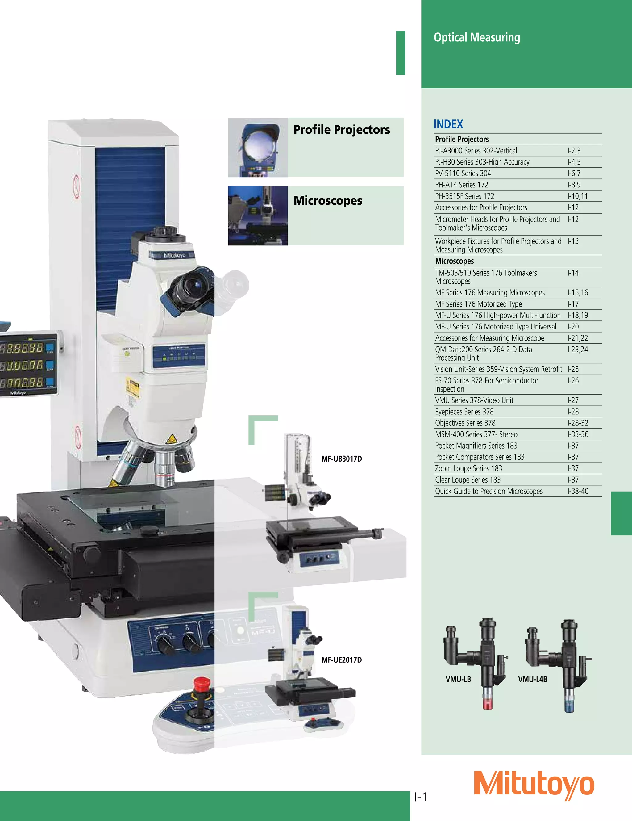
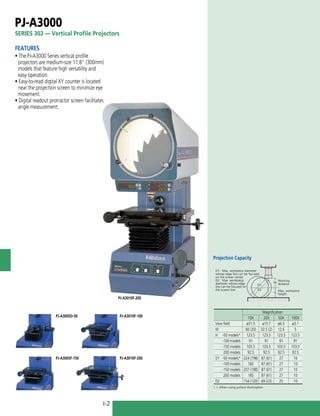
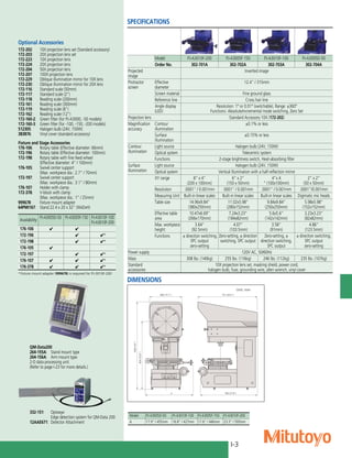


This document provides an index and specifications for various optical measuring instruments, including profile projectors and microscopes. It lists several models of profile projectors from the PJ-A3000 and PJ-H30 series, along with their specifications, optional accessories, and available fixtures. It also lists several models of measuring microscopes from the MF, MF-U, and MSM-400 series, along with their specifications and optional accessories. The document provides detailed information on the specifications, features, and options for these optical measuring instruments.


