Download to read offline
![Page No.1
College OF Engineering Pune
CHAPTER 1
INTRODUCTION
1.1 INTRODUCRION
Due to any major injury if any person loses his or her major working arm then it
becomes very difficult for a person to live normal life. Some times person becomes inactive
and depressed.
To overcome this problem, We are developing a Mechatronics system which will
aesthetically looks like normal human hand and will be able to perform basic operations like
gripping, holding, placing of object etc. for this purpose, currently a prosthetic hand is
available in which each finger is actuated using brain signals and operations are carried out.
Since cost of the system is very high we are planning to develop a low cost and much simpler
system.
1.1. Physiology of hand[15]
The amputee person is having muscles and tissues but the activity is depending on muscles
stimulation. In our design, muscle activity of forearm will be sensed and it will be responsible
for finger motions. Muscle activity is sensed by the surface electrodes and sensing circuitry
will give output signal to the controller board. The controller will control the direction of the](https://image.slidesharecdn.com/finalreport11-141208010112-conversion-gate02/75/Final-report-1_-_1_-1-2048.jpg)

![Page No.5
College OF Engineering Pune
CHAPTER 2
BACKGROUND AND LITERATURE REVIEW
The prosthetic hands are commonly used in artificial limb replacement area. It is
merely medical related term. The existing techniques for amputee are spring operated hand
which is actuated by movement of shoulder of the body. These hands are mainly use to hide
the amputee area and use for minimum daily work. Below are the few artificial prosthetic
hands.
2.1 Upper limb prostheses
Upper limb prosthetic devices are either passive or active. Passive prostheses, with no
moving parts, are generally used for cosmetic purposes. Active prostheses may be body-powered
or externally-powered. Hybrids of these two systems are also available. A body-powered
prosthesis usually employs a harness and cables. A variety of terminal devices
(hooks, hands) can be attached. According to LeBlanc (1988), 28% of prehensors in use in
the US were hands (both passive and active); whereas in the UK, West Germany and Sweden
the percentage of hand prehensors were 76%, 88%, and 70%, respectively[2]. The advantages
of body-powered prostheses include: simple operational mechanisms with intrinsic skeletal
movement (which voluntarily opens/closes a terminal device), silent action, light weight,
moderate cost, durability and reliability, and rough sensory feedback about the positioning of
the terminal device. They are utilized more often in less-developed countries with scarce
medical and rehabilitation infrastructure and technical resources. As Bhaskaranand points
out, prosthetic rehabilitation of patients with financial constraints requires durable and low
cost prostheses[1]. Body-powered prostheses are also preferred by amputees living in rural
areas (far from prosthetic centres), as well as by workers who are in labour-intensive manual
and outdoor occupations. In general, prostheses used at challenging work environments are at
a higher risk of exposure to corrosive materials, water or heat.](https://image.slidesharecdn.com/finalreport11-141208010112-conversion-gate02/75/Final-report-1_-_1_-5-2048.jpg)
![Page No.6
College OF Engineering Pune
2.1.1 Spring operated hand:-
In this technique, the hand is operated by spring tension. Normally these fingers are in
ideal positions as shown above in fig. The spring is connected to shoulder by some
mechanical strings.
Fig.2.1 Spring operated prosthetic hand. [16]
Whenever patient jerks the oulder, strings pull the spring and accordingly fingers are opened.
Main fact is, only three fingers are in actual operation. The little finger and ring finger are
dummy and used only for aesthetically sound design.
When person actuates the fingers trough cable from shoulder, the three fingers opens and
closes immediately releases the tension. Silent control of fingers is not possible because of its
structure. The system is made up of metallic parts cause heaviness.
Cost of the system is less and economical for poor peoples. Comparing to operation and cost,
it is very ideal product.
2.1.2 Myoelectric prostheses
Myoelectric technology uses electromyographic (EMG) activity, a form of electrical
signal, from the voluntary movements of the stump muscles. EMG signals, which control the
flow of energy from the battery to the electric motor, are captured through surface electrodes.
The amplitude of the EMG signal is generally proportional to the contraction of the residual
muscle. After amplification and transmission, the myoelectric control system activates the
electric motor to operate the terminal device. Surface electrodes can be affected by donning,](https://image.slidesharecdn.com/finalreport11-141208010112-conversion-gate02/75/Final-report-1_-_1_-6-2048.jpg)
![Page No.7
or by surface conditions such as perspiration. As well, during the journey from the muscle to
the skin‘s surface, EMG signals may encounter noise and interference from other tissues. One
option to increase signal control is needle/implant electrodes inserted into active muscle
fibres. However, this approach is not immune to many technical issues and introduces its own
pros and cons. More information about implantable electrodes can be found elsewhere. The
motion of the wrist and terminal device are controlled by myoelectric sensors located either
at a single site (muscle) or dual sites. Switching between the two different modes (wrist or
terminal device) is usually directed by proportional control (fast or slow muscle contraction)
or simultaneous control (muscle co-contraction) [upp/55][59]. In proportional control, the
power of the muscle determines the speed or force of the prosthetic device[upp/60].
Advanced sockets (integrating sensors and metal connections within silicone) and
elastomeric liners have helped improve EMG signal acquisition[upp/55]. The incorporation
of programmable microprocessors in myoelectric prostheses increases the adjustment range
for EMG signal characteristics and the modification of prosthetic control parameters. Using
microprocessors, EMG signals are filtered and a real-time signal analysis is provided.
Microprocessors also accommodate pattern recognition-based control, which increases
functionality of the prosthesis with higher involvement/input of the user and, in return,
decreases the cost and time involved during initial fitting
College OF Engineering Pune
2.1.1 Commercially available hand:-
Fig.2.2 Commercial Myoelectric hand [6]](https://image.slidesharecdn.com/finalreport11-141208010112-conversion-gate02/75/Final-report-1_-_1_-7-2048.jpg)
![Page No.8
In this technique, each finger is actuated separately with separate mechanism. These fingers
are operated by small dc motors with the sensing of brain signals. The intermediate system is
very complex and bulky. The EEG signals from the brain are sensed and processed using
high capacity filters and electronic circuits. These fingers motions are aesthetically same as
real human fingers. The cost of the hand is very high.
College OF Engineering Pune
2.2 Review of literature
- Analyzing and comparing incidence and prevalence rates of amputations is
frequently unreliable. Data collection methods vary across countries and even across
jurisdictions within the same country.30
- Frequently, studies on patients with upper limb prostheses have limited numbers of
study subjects. Study teams from different prosthetic rehabilitation centers would do well to
collaborate to maximize sample size and enhance the validity of their research. A lack of
standard outcome measures frequently restricts this integration and limits the comparison of
findings from individual studies [3].
- The majority of the studies on upper limb myoelectric prostheses have used
questionnaire surveys only [5]. Other authors have employed questionnaires in addition to
other study methods [6] while a number were either clinical/comparative studies or were
chart reviews without questionnaires [4]
- Occasionally, studies compare control systems of various prosthetics without
keeping terminal devices constant across compared groups [7].
- Prosthetic studies performed in laboratory settings usually have results based on
optimal conditions, rather than real life conditions [8]. Many of the published studies on
myoelectric prostheses are based on experimental hands or prosthetic features being studied
in research laboratories of the manufacturers/universities.](https://image.slidesharecdn.com/finalreport11-141208010112-conversion-gate02/75/Final-report-1_-_1_-8-2048.jpg)

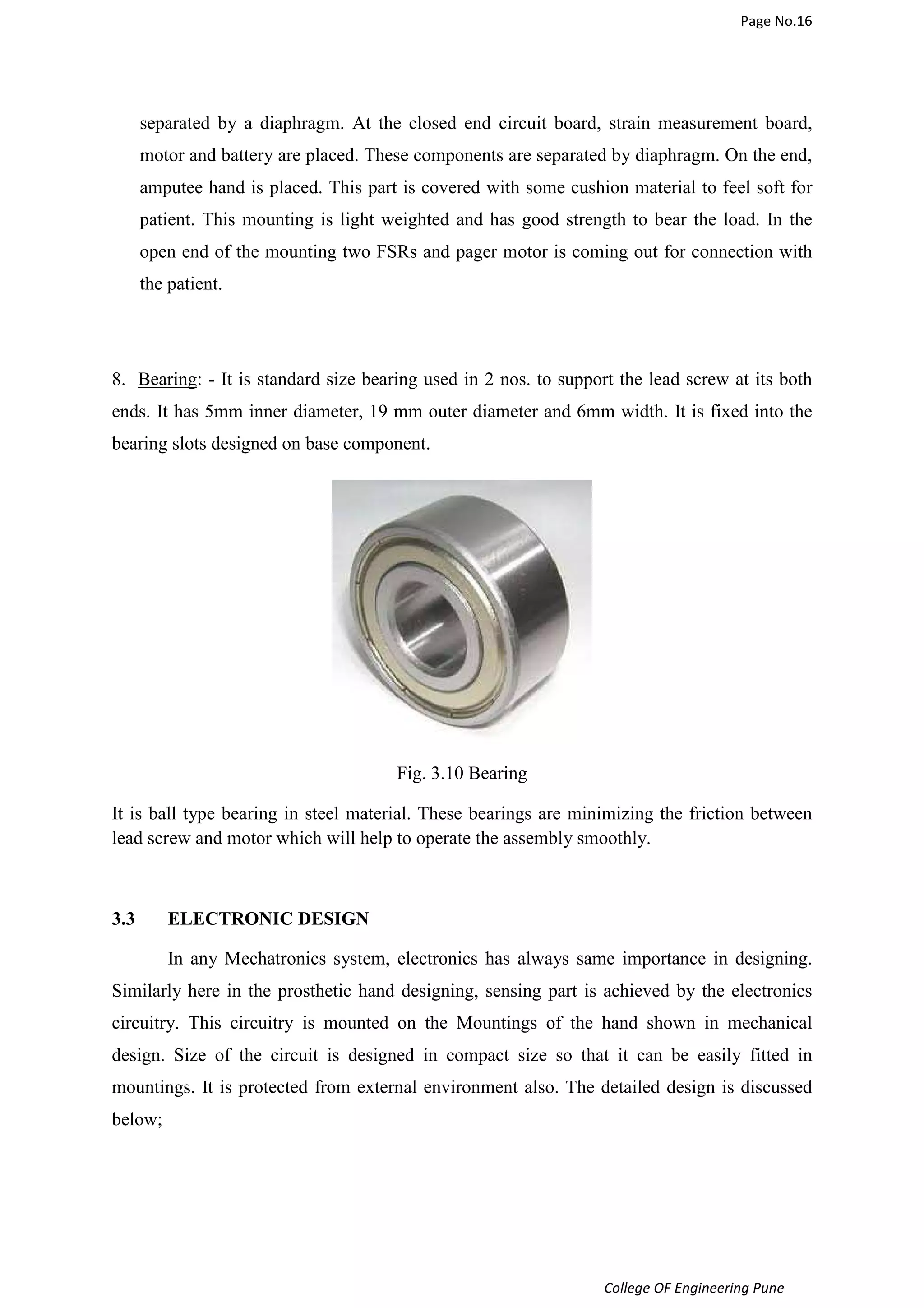
![Page No.17
College OF Engineering Pune
Strain Gauge (BF AA series )
Fig.3.11 Strain gauge [10]
Karma material is a nickel chromium alloy which can be used for strain sensing. The
characteristics of the alloy compared with standard constantan alloy strain gages are as
follows:
• Improved fatigue life.
• Excellent Stability over a wide temperature range.
• A much flatter thermal output curve which provides for more accurate
Thermal correction over a wider temperature range.
• A higher resistivity which enables higher resistance strain gages for
The same size or same resistance in a smaller size.
Karma gages are available with temperature characteristics matched to stainless steel or
aluminum. Karma is known to be difficult to solder, even with special flux. OMEGA is
offering ribbon leads or copper plated solder pads, so that standard soldering techniques can
be used, making wiring easier [10].
Creep compensation is available for Karma strain gages. It may be necessary in transducer
design to match the strain gage transducer creep characteristics to the spring element. Karma
strain gages are labeled with a letter code which identifies a creep code value. The creep
characteristics of a strain gage pattern can be modified by varying the length of the end loops
and the limb or strand width. Creep codes are a ratio of the end loop length to the limb width.](https://image.slidesharecdn.com/finalreport11-141208010112-conversion-gate02/75/Final-report-1_-_1_-17-2048.jpg)
![Page No.18
An increasing ratio will give a longer end loop and a more positive creep characteristic.
OMEGA will work with you to develop the custom creep value needed for your application.
K-Series strain gages are suggested for static strain measurement over a wide temperature
range from -75 to 200°C (-100 to 392°F) due to their good linearity over this wide
temperature range.
K-Series strain gages are often used for fatigue-rated transducer designs. The fatigue life of
Karma alloy tends to be much better than constantan, and so transducers using Karma strain
gages provide good fatigue life. You will notice if you compare the fatigue specifications that
Karma is rated at ±1800 micro strain, 10,000,000 cycles, and constantan is rated at SGD
series is rated at ±1500 micro strain, 10,000,000 cycles. A transducer designed at ±1500
micro[11].
Fig3.12 Strain Gauge Specification [11]
College OF Engineering Pune](https://image.slidesharecdn.com/finalreport11-141208010112-conversion-gate02/75/Final-report-1_-_1_-18-2048.jpg)
![Page No.19
College OF Engineering Pune
3.3.1 Force Sensing Resistor FSR
A force-sensing resistor is a material whose resistance changes when
a force or pressure is applied. They are also known as force-sensitive resistor and are
sometimes referred to by the initialize FSR.
Force-sensing resistors consist of a conductive polymer, which changes resistance in a
predictable manner following application of force to its surface. They are normally supplied
as a polymer sheet or ink that can be applied by screen printing. The sensing film consists of
both electrically conducting and non-conducting particles suspended in matrix. The particles
are sub-micrometre sizes, and are formulated to reduce the temperature dependence, improve
mechanical properties and increase surface durability. Applying a force to the surface of a the
sensing film causes particles to touch the conducting electrodes, changing the resistance of
the film. As with all resistive based sensors, force-sensing resistors require a relatively simple
interface and can operate satisfactorily in moderately hostile environments. Compared to
other force sensors, the advantages of FSRs are their size (thickness typically less than
0.5 mm), low cost and good shock resistance. However, FSRs will be damaged if pressure is
applied for a longer time period (hours). A disadvantage is their low precision: measurement
results may differ 10% and more [12].
Fig3. 13 FSR Sensor [12]](https://image.slidesharecdn.com/finalreport11-141208010112-conversion-gate02/75/Final-report-1_-_1_-19-2048.jpg)
![Page No.21
College OF Engineering Pune
3.3.2 Microcontroller Atmega8 (Atmel)
The Atmel®AVR® ATmega8 is a low-power CMOS 8-bit microcontroller based on
the AVR RISC
Architecture. By executing powerful instructions in a single clock cycle, the ATmega8
achieves
Throughputs approaching 1MIPS per MHz, allowing the system designer to optimize power
consumption versus processing speed [13].
Features
• High-performance, Low-power Atmel®AVR® 8-bit Microcontroller
• Advanced RISC Architecture
– 130 Powerful Instructions – Most Single-clock Cycle Execution
– 32 × 8 General Purpose Working Registers
– Fully Static Operation
– Up to 16MIPS Throughput at 16MHz
– On-chip 2-cycle Multiplier
• High Endurance Non-volatile Memory segments
– 8Kbytes of In-System Self-programmable Flash program memory
– 512Bytes EEPROM
– 1Kbyte Internal SRAM
– Write/Erase Cycles: 10,000 Flash/100,000 EEPROM
– Data retention: 20 years at 85°C/100 years at 25°C
– Optional Boot Code Section with Independent Lock Bits
• Peripheral Features](https://image.slidesharecdn.com/finalreport11-141208010112-conversion-gate02/75/Final-report-1_-_1_-21-2048.jpg)
![Page No.22
– Two 8-bit Timer/Counters with Separate Presales, one Compare Mode
– One 16-bit Timer/Counter with Separate Presales, Compare Mode, and Capture
College OF Engineering Pune
• Eight Channels 10-bit Accuracy
– 6-channel ADC in PDIP package
• Six Channels 10-bit Accuracy
Fig3.14. Atmega8 microcontroller[13]
– Byte-oriented Two-wire Serial Interface
– Programmable Serial USART
– Master/Slave SPI Serial Interface
– Programmable Watchdog Timer with Separate On-chip Oscillator
– On-chip Analog Comparator](https://image.slidesharecdn.com/finalreport11-141208010112-conversion-gate02/75/Final-report-1_-_1_-22-2048.jpg)
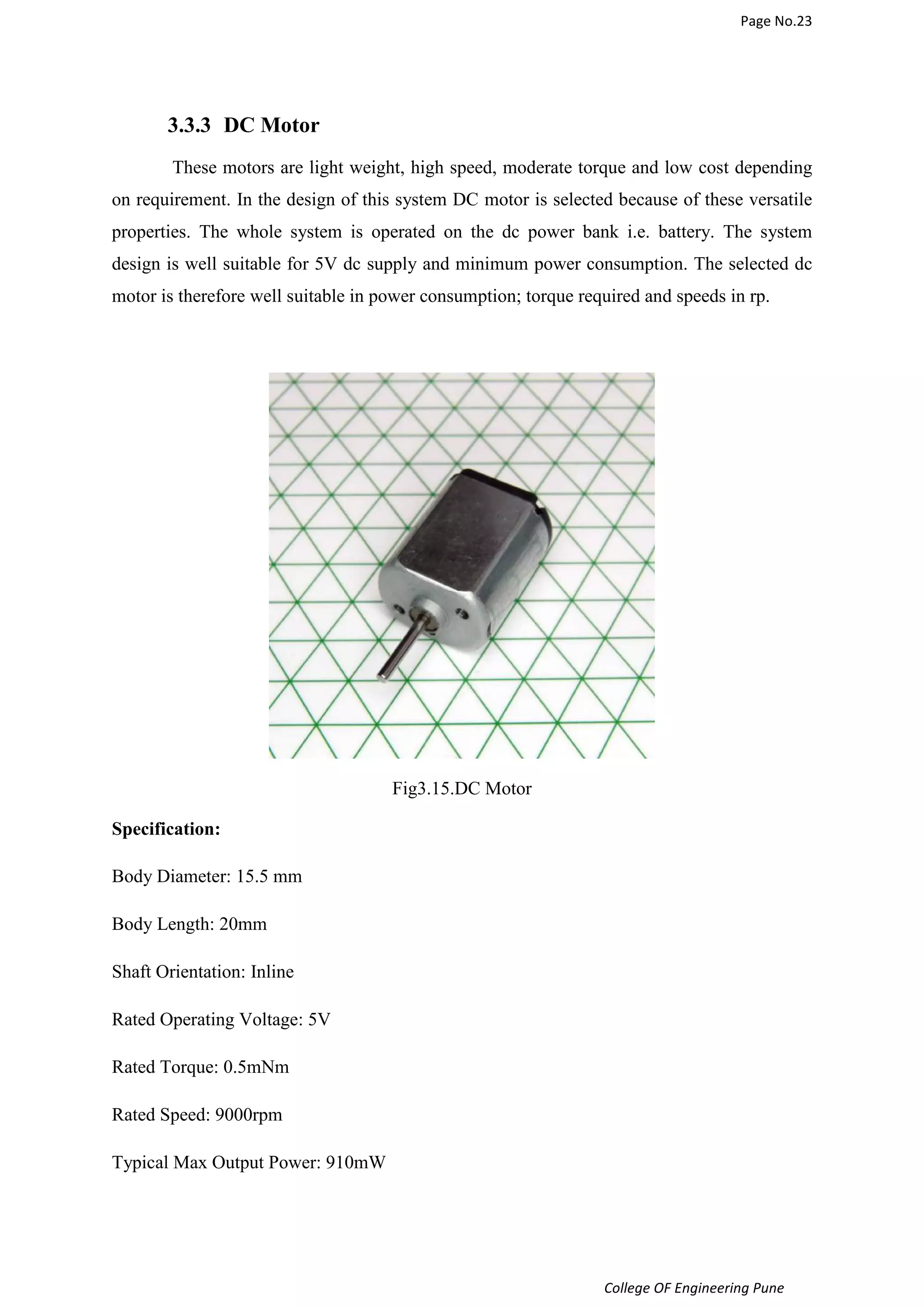
![Page No.24
3.3.4 Vibration Motor
These tiny and feisty motors have offset weights that make them vibrate when they
spin. They're normally called pager motors because they're the type found in pagers and
cell phones that have a vibrate feature.
What to do with them? Well for starters, they're the perfect thing for making Bristle bots,
vibrobots, BEAM bots, and other tiny robots. They have wire leads attached that are color
coded and pre-stripped on the ends. These motors can be driven with 3 V coin cells like the
CR2032. Each one comes in a removable rubber boot that has one flat side for easy mounting
[14].
College OF Engineering Pune
Fig.3.16 Pager motor [14]
Specifications:
Nominal voltage: 3 V
Operating voltage: 2.5 ~ 3.5 V
Rated current: 85 mA
Nominal speed: 12000 RPM
Diameter: 5mm
Length: 8mm](https://image.slidesharecdn.com/finalreport11-141208010112-conversion-gate02/75/Final-report-1_-_1_-24-2048.jpg)
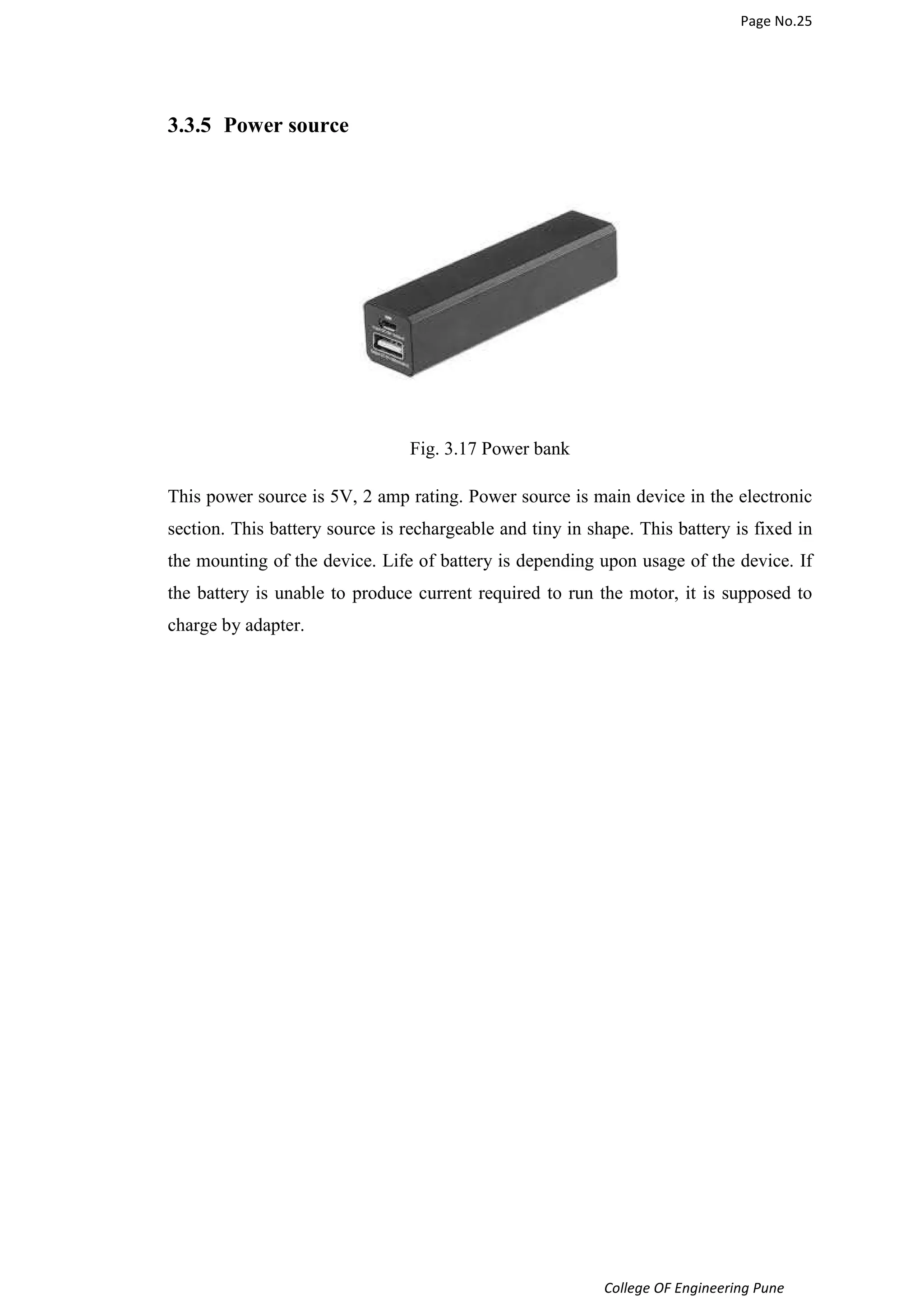

![Page No.37
College OF Engineering Pune
REFERANCES
[1]. 43. Bhaskaranand K, Bhat AK, Acharya KN. Prosthetic rehabilitation in traumatic upper limb
amputees (an Indian perspective). Arch Orthop Trauma Surg. 2003 Sep;123(7):363-6.
[2]. LeBlanc M. Use of prosthetic prehensors. Prosthet Orthot Int. 1988 Dec;12(3):152-4.
[3]. Biddiss EA, Chau TT. Upper limb prosthesis use and abandonment: a survey of the last 25
years. Prosthet Orthot Int. 2007 Sep;31(3):236-57.
[4]. Kyberd PJ, Beard DJ, Morrison JD. The population of users of upper limb prostheses
attending the Oxford Limb Fitting Service. Prosthet Orthot Int. 1997 Aug;21(2):85-91.
[5]. Biddiss E, Chau T. Upper-limb prosthetics: critical factors in device abandonment. Am J Phys
Med Rehabil. 2007 Dec;86(12):977-87.
[6]. Datta D, Kingston J, Ronald J. Myoelectric prostheses for below-elbow amputees: the Trent
experience. Int Disabil Stud. 1989 Oct-Dec;11(4):167-70
[7]. Weaver SA, Lange LR, Vogts VM. Comparison of myoelectric and conventional prostheses
for adolescent amputees. Am J Occup Ther. 1988 Feb;42(2):87-91.
[8]. Hacking H. Long-term outcome of upper limb prosthetic use in the Netherlands European
Journal of Physical Medicine and Rehabilitation 1997;7(6):179-81.
[9]. A. L. Window Strain Gauge Technology, 1992 :Elsevier Applied Science
[10]. Strain gauge BF AA 350 10 (online) available on http://www.omega.com/techref/strain-gage.
html
[11]. Strain gauge manual (online) available on
http://www.omega.com/manuals/index.html?s=all
[12]. FSR details (online) available on http://www.instructables.com/id/FSR-Tutorial/
[13]. AVR atmega 32 microcontroller (online) available on
http://www.atmel.com/products/microcontrollers/avr/default.aspx
[14]. Pager motor details (online) available on
http://shop.evilmadscientist.com/productsmenu/partsmenu/131-pagermotor
[15]. Hand palm anatomy available (online) http://ittcs.wordpress.com/2010/10/31/notes-on-anatomy-
and-physiology-the-hand-and-the-tigers-mouth/
[16]. Spring operated hand paper by M.C. CARROZZA R. LAZZARINI M.R. CUTKOSKY The SPRING
Hand: Development of a Self-Adaptive Prosthesis for Restoring Natural Grasping Autonomous
Robots 16, 125–141, 2004_c 2004 Kluwer Academic Publishers. Manufactured in The
Netherlands](https://image.slidesharecdn.com/finalreport11-141208010112-conversion-gate02/75/Final-report-1_-_1_-37-2048.jpg)

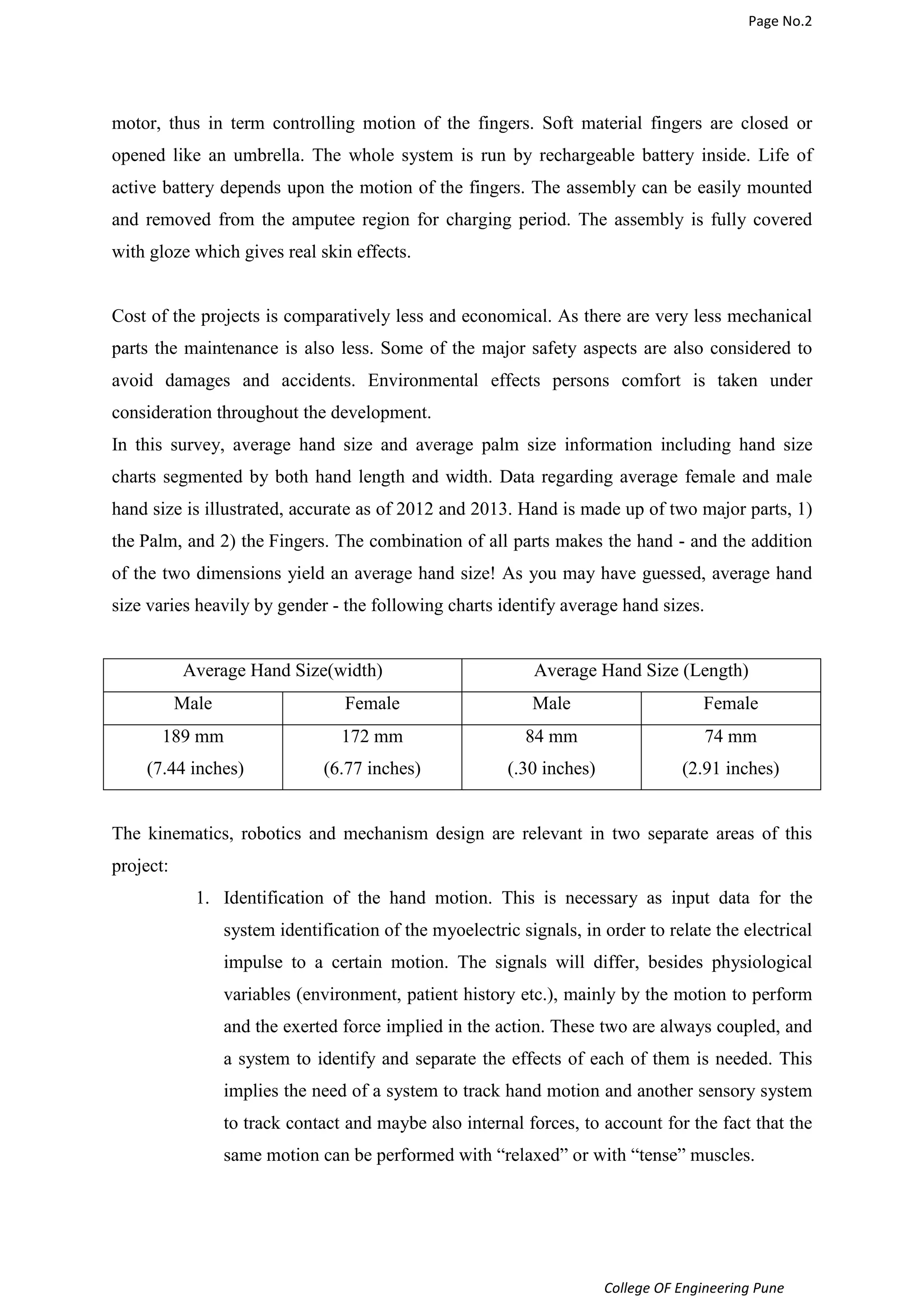
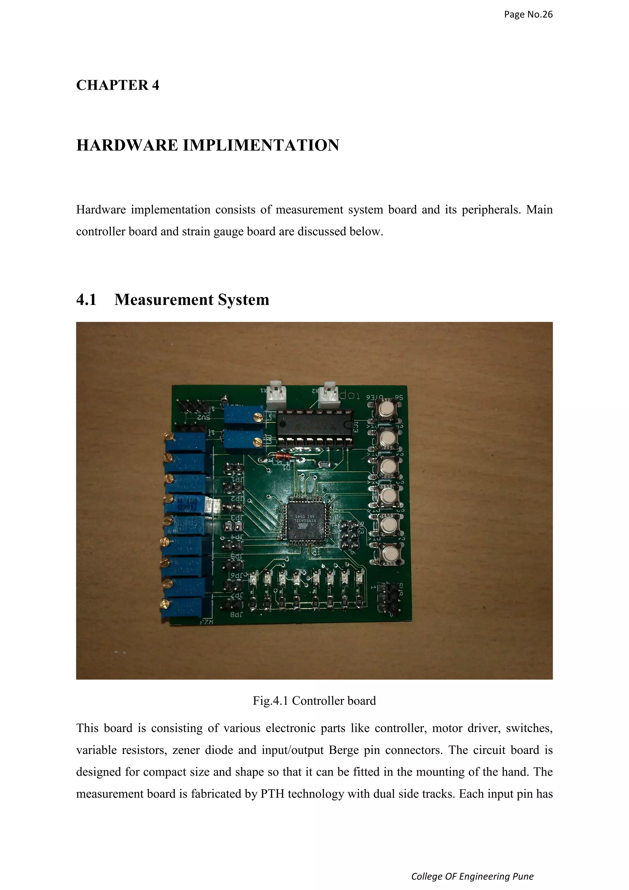
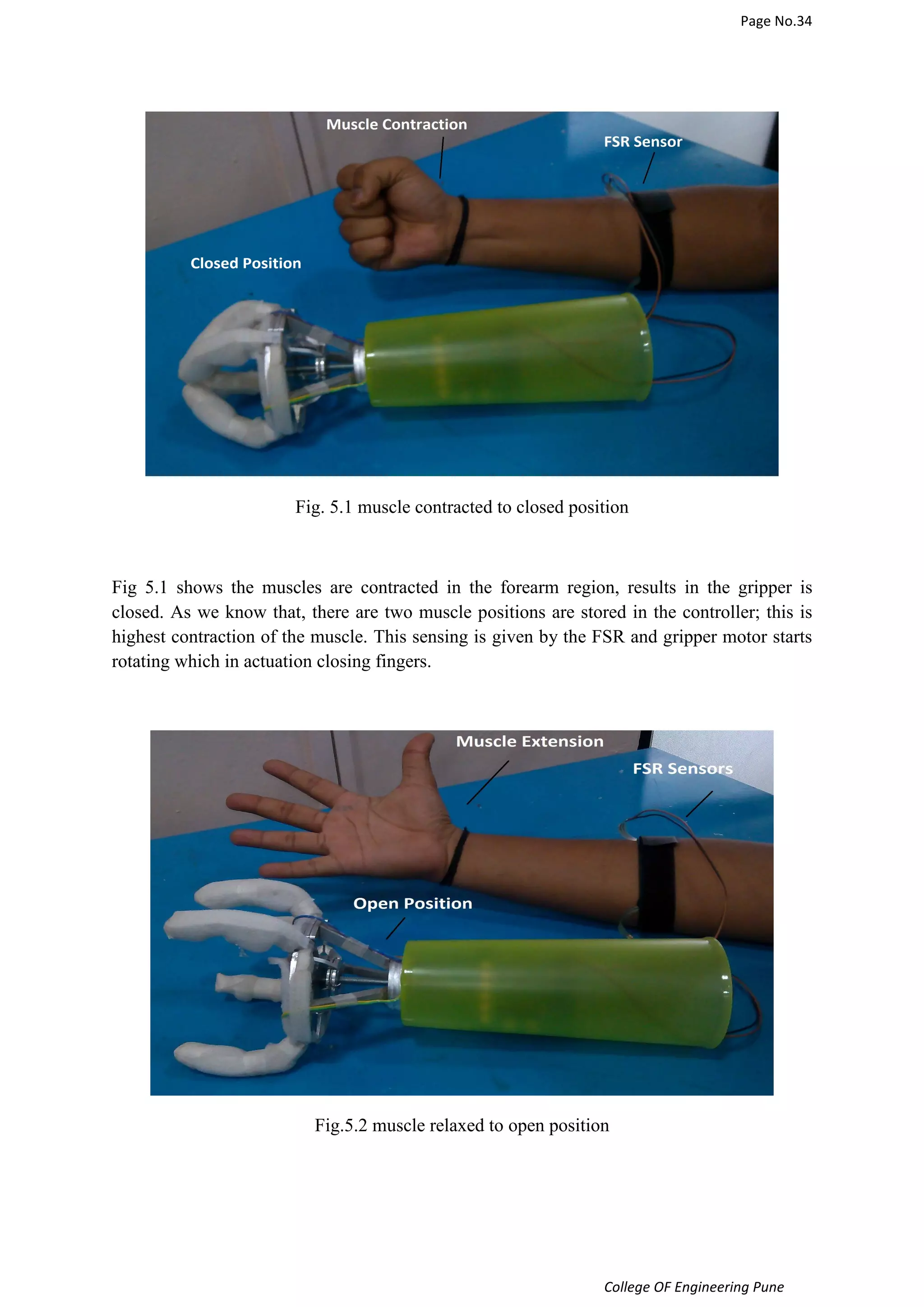
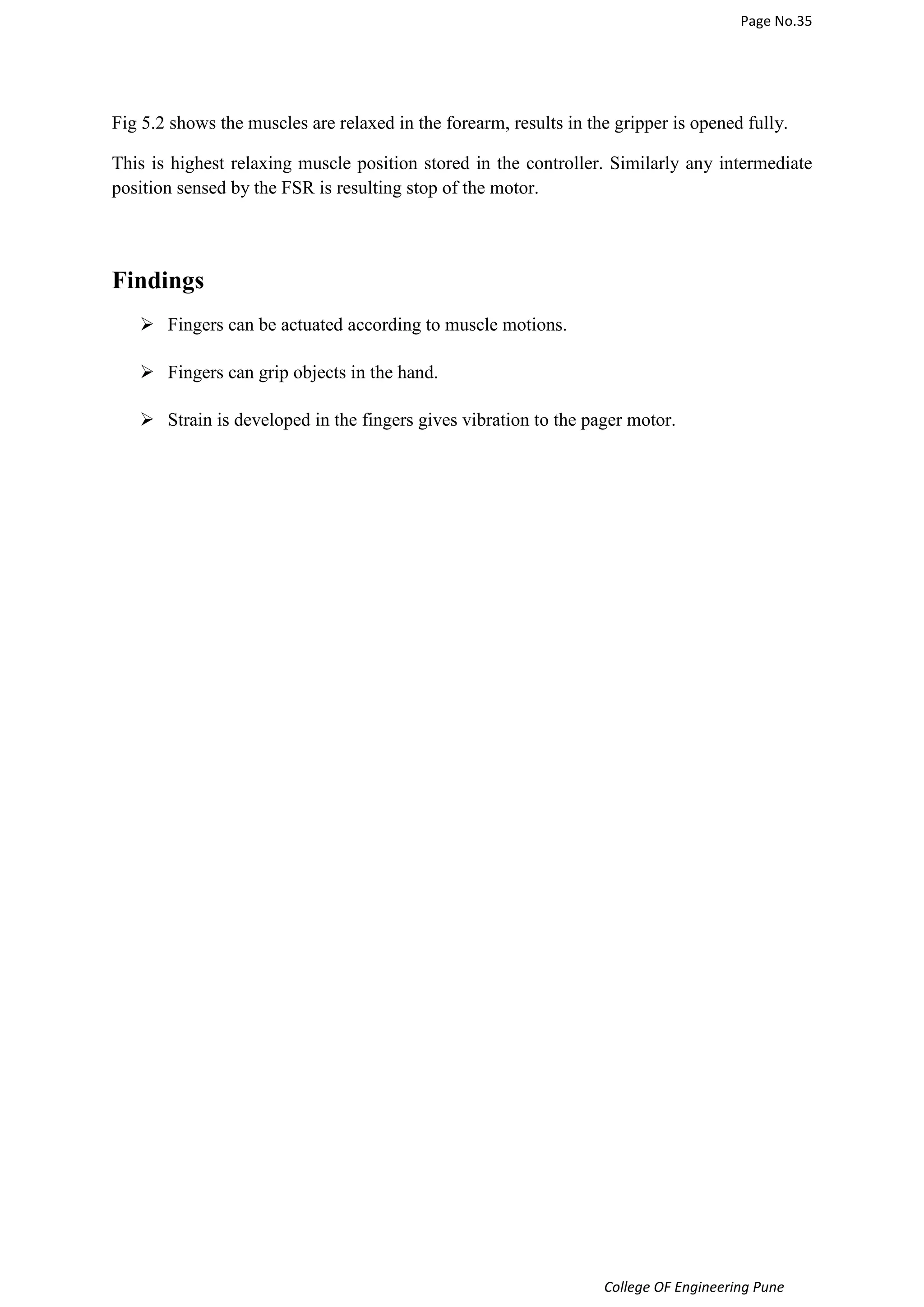
This document discusses the development of a low-cost prosthetic hand for people who have lost the use of their arm. It aims to design a hand that can perform basic grasping and holding functions through the sensing of muscle activity in the forearm. The system would use low-cost materials and motors to open and close soft prosthetic fingers similar to an umbrella opening and closing. This would provide an affordable alternative to existing high-cost prosthetics that use complex brain-signal control. The document reviews different types of existing prosthetic hands and the mechanics, electronics, and safety aspects considered in the design project.


