Downloaded 161 times


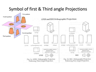


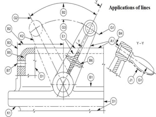
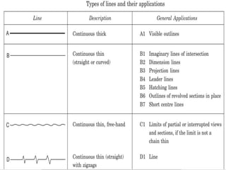


The document discusses various machine drawing conventions including scale, which is the ratio of dimensions on a drawing to the actual object; sectioning, where cutting planes are used to show internal details and designated with capital letters; and different line types used for graphical representation in technical drawings. Specific machine elements like ribs and shafts are not cut or hatched in longitudinal sections.


