Downloaded 146 times


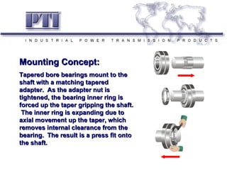


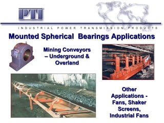


P.T. International Corp. provides power transmission products including mounted bearings, drive products, and European linear components. They are headquartered in Charlotte, NC with an 80,000 square foot facility stocking over 25,000 SKUs. The document discusses their global manufacturing and sourcing, engineering capabilities, and ISO 9001:2008 certification. It also provides details on their product range, inspection processes, and installation guidelines for mounted spherical bearings.