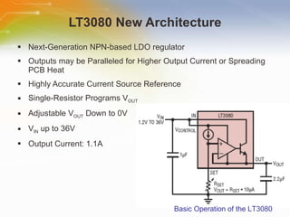
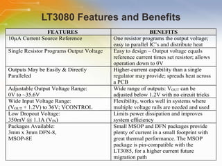
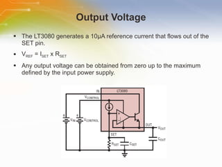
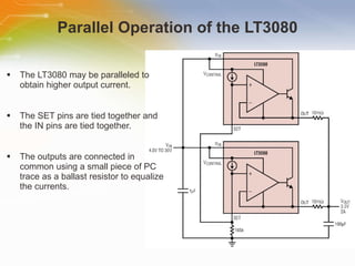
Introducing the LT3080   -  Adjustable 1.1A Single Resistor LDO Regulator   Source:  LINEAR TECHNOLOGY
Introduction Purpose This training module introduces the new architecture of adjustable linear regulators from Linear Technology.  Outline Overview of the LT3080 adjustable linear regulator New architecture of the LT3080 Basic operations & key features Applications Content 15 pages
What is the LT3080? The LT3080 is . . .  An NPN 1.1A Adjustable Single-Resistor LDO Directly Paralleled for PCB Heat Spreading Easy to set V OUT  – only a single resistor needed
LT3080 New Architecture Next-Generation NPN-based LDO regulator Outputs may be Paralleled for Higher Output Current or Spreading PCB Heat Highly Accurate Current Source Reference Single-Resistor Programs V OUT Adjustable V OUT  Down to 0V V IN  up to 36V  Output Current: 1.1A Basic Operation of the LT3080
LT3080 Features and Benefits
Output Voltage The LT3080 generates a 10μA reference current that flows out of the SET pin. V REF  = I SET  x R SET  Any output voltage can be obtained from zero up to the maximum defined by the input power supply.
Parallel Operation of the LT3080 The LT3080 may be paralleled to obtain higher output current. The SET pins are tied together and the IN pins are tied together. The outputs are connected in common using a small piece of PC trace as a ballast resistor to equalize the currents.
Paralleled with Fixed Output Regulators The   LT3080   may   also   be   paralleled   with   fixed   output   regulators   to   supplement   the   output   current   of   a   single   device. It   is   necessary   to   use   15   to   20   m Ω   of   ballast   resistance   to   cause   the   two   ICs   to   share. A   point   for   connecting   the   set   pin   of   the   LT3080   must   be   provide. A   divider   from   the   output   of   the   fixed   regulator   provides   a   voltage   about   4   mV   lower   than   the   fixed   output.
Thermal Performance
Quieting the Noise Several sources of noise in traditional linear regulators are from: the reference the error amplifier Gain from a resistor divider Solution: The LT3080 does not use a traditional voltage reference but instead uses a reference current. The LT3080 uses a unity-gain follower from the SET pin to drive the output, and there is no requirement to use a resistor to set the output voltage.
Reducing Power Dissipation Two techniques can reduce the power dissipation of the LT3080. Using a series resistor (R S ) Using a Parallel Resistor (R P ) P TOTAL  = P DRIVE  + P OUTPUT P OUTPUT  = (V IN  – V OUT )(I OUT ) P DRIVE  = (V CONTROL  – V OUT )(I CONTROL ) Figure 1 Figure 2
Current Source Configuration To provide frequency compensation To provide frequency compensation
LED Driver Configuration
Lab Supply Configuration
Additional Resource For ordering the LT3080, please click the part list or Call our sales hotline For additional inquires contact our technical service hotline For more product information go to http://www.linear.com/pc/productDetail.jsp?navId=H0,C1,C1003,C1040,C1055,P38503 Newark Farnell

Introducing the LT3080 - Adjustable 1.1A Single Resistor LDO Regulator

  • 1.
    Introducing the LT3080 - Adjustable 1.1A Single Resistor LDO Regulator Source: LINEAR TECHNOLOGY
  • 2.
    Introduction Purpose Thistraining module introduces the new architecture of adjustable linear regulators from Linear Technology. Outline Overview of the LT3080 adjustable linear regulator New architecture of the LT3080 Basic operations & key features Applications Content 15 pages
  • 3.
    What is theLT3080? The LT3080 is . . . An NPN 1.1A Adjustable Single-Resistor LDO Directly Paralleled for PCB Heat Spreading Easy to set V OUT – only a single resistor needed
  • 4.
    LT3080 New ArchitectureNext-Generation NPN-based LDO regulator Outputs may be Paralleled for Higher Output Current or Spreading PCB Heat Highly Accurate Current Source Reference Single-Resistor Programs V OUT Adjustable V OUT Down to 0V V IN up to 36V Output Current: 1.1A Basic Operation of the LT3080
  • 5.
  • 6.
    Output Voltage TheLT3080 generates a 10μA reference current that flows out of the SET pin. V REF = I SET x R SET Any output voltage can be obtained from zero up to the maximum defined by the input power supply.
  • 7.
    Parallel Operation ofthe LT3080 The LT3080 may be paralleled to obtain higher output current. The SET pins are tied together and the IN pins are tied together. The outputs are connected in common using a small piece of PC trace as a ballast resistor to equalize the currents.
  • 8.
    Paralleled with FixedOutput Regulators The LT3080 may also be paralleled with fixed output regulators to supplement the output current of a single device. It is necessary to use 15 to 20 m Ω of ballast resistance to cause the two ICs to share. A point for connecting the set pin of the LT3080 must be provide. A divider from the output of the fixed regulator provides a voltage about 4 mV lower than the fixed output.
  • 9.
  • 10.
    Quieting the NoiseSeveral sources of noise in traditional linear regulators are from: the reference the error amplifier Gain from a resistor divider Solution: The LT3080 does not use a traditional voltage reference but instead uses a reference current. The LT3080 uses a unity-gain follower from the SET pin to drive the output, and there is no requirement to use a resistor to set the output voltage.
  • 11.
    Reducing Power DissipationTwo techniques can reduce the power dissipation of the LT3080. Using a series resistor (R S ) Using a Parallel Resistor (R P ) P TOTAL = P DRIVE + P OUTPUT P OUTPUT = (V IN – V OUT )(I OUT ) P DRIVE = (V CONTROL – V OUT )(I CONTROL ) Figure 1 Figure 2
  • 12.
    Current Source ConfigurationTo provide frequency compensation To provide frequency compensation
  • 13.
  • 14.
  • 15.
    Additional Resource Forordering the LT3080, please click the part list or Call our sales hotline For additional inquires contact our technical service hotline For more product information go to http://www.linear.com/pc/productDetail.jsp?navId=H0,C1,C1003,C1040,C1055,P38503 Newark Farnell