UNIT-V FMM.HYDRAULIC TURBINE - Construction and working
000dbe0c ea9c-11e5-a7cc-6cae8b4eb554.data
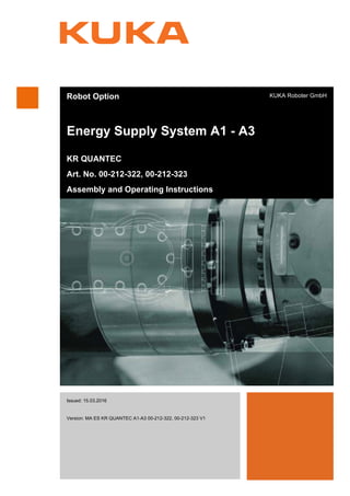
1. Robot Option
Energy Supply System A1 - A3
KR QUANTEC
Art. No. 00-212-322, 00-212-323
Assembly and Operating Instructions
KUKA Roboter GmbH
Issued: 15.03.2016
Version: MA ES KR QUANTEC A1-A3 00-212-322, 00-212-323 V1
Energy Sup-
ply System A1
- A3
3. 3 / 35Issued: 15.03.2016 Version: MA ES KR QUANTEC A1-A3 00-212-322, 00-212-323 V1
Contents
1 Introduction .................................................................................................. 5
1.1 Documentation for the options ................................................................................... 5
1.2 Representation of warnings and notes ...................................................................... 5
2 Purpose ........................................................................................................ 7
2.1 Target group .............................................................................................................. 7
2.2 Intended use .............................................................................................................. 7
3 Product description ..................................................................................... 9
3.1 Description of energy supply system A1 - A3 ............................................................ 9
4 Technical data .............................................................................................. 15
4.1 Basic data .................................................................................................................. 15
4.2 Interface A1 ............................................................................................................... 15
4.3 Interface A3 ............................................................................................................... 16
4.4 Dress package ........................................................................................................... 16
4.4.1 Control cable ......................................................................................................... 16
4.4.2 Profinet cable ........................................................................................................ 17
4.4.3 Sensor cable ......................................................................................................... 18
4.4.4 Sensor cable ......................................................................................................... 19
4.4.5 Air line, blue .......................................................................................................... 20
4.4.6 Air line, black ........................................................................................................ 21
5 Safety ............................................................................................................ 23
5.1 Safety of the option .................................................................................................... 23
6 KUKA Service .............................................................................................. 25
6.1 Requesting support .................................................................................................... 25
6.2 KUKA Customer Support ........................................................................................... 25
Index ............................................................................................................. 33
Contents
4. 4 / 35 Issued: 15.03.2016 Version: MA ES KR QUANTEC A1-A3 00-212-322, 00-212-323 V1
Energy Supply System A1 - A3
5. 5 / 35Issued: 15.03.2016 Version: MA ES KR QUANTEC A1-A3 00-212-322, 00-212-323 V1
1 Introduction
1 Introduction
1.1 Documentation for the options
The documentation for this option consists of the following parts:
Assembly and operating instructions for energy supply systems for this ro-
bot model (basic documentation)
Assembly and operating instructions for the article number-specific energy
supply system
Parts catalog for this option on storage medium
Assembly and operating instructions for the higher-level system
Each of these sets of instructions is a separate document.
The basic documentation “Assembly and operating instructions for energy
supply system” contains all essential information for all energy supply systems
for this robot model, but does not go into the specific details of a particular en-
ergy supply system. This information can be found in another document, the
“Article number-specific assembly and operating instructions”. This contains
all the information which only applies to a specific energy supply system (arti-
cle number). Both documents must be consulted for basic information.
1.2 Representation of warnings and notes
Safety These warnings are relevant to safety and must be observed.
This warning draws attention to procedures which serve to prevent or remedy
emergencies or malfunctions:
Notices These notices serve to make your work easier or contain references to further
information.
t
t
These warnings mean that it is certain or highly probable
that death or severe injuries will occur, if no precautions
are taken.
These warnings mean that death or severe injuries may
occur, if no precautions are taken.
These warnings mean that minor injuries may occur, if
no precautions are taken.
These warnings mean that damage to property may oc-
cur, if no precautions are taken.
These warnings contain references to safety-relevant information or
general safety measures.
These warnings do not refer to individual hazards or individual pre-
cautionary measures.
Procedures marked with this warning must be followed
exactly.
Tip to make your work easier or reference to further information.
6. 6 / 35 Issued: 15.03.2016 Version: MA ES KR QUANTEC A1-A3 00-212-322, 00-212-323 V1
Energy Supply System A1 - A3
7. 7 / 35Issued: 15.03.2016 Version: MA ES KR QUANTEC A1-A3 00-212-322, 00-212-323 V1
2 Purpose
2 Purpose
2.1 Target group
This documentation is aimed at users with the following knowledge and skills:
Advanced knowledge of mechanical engineering
Advanced knowledge of electrical and electronic systems
Knowledge of the robot controller system
2.2 Intended use
Use The intended use of the energy supply system is the supply of energy to tools
and fixtures on the robot. This includes the transmission of control and mea-
suring signals for activating and monitoring tools and fixtures and the supply
of air and water.
Operating the system within the limits of its intended use also involves contin-
uous observance of the operating and assembly instructions of the robot sys-
tem and its options, with particular reference to the maintenance
specifications.
Misuse Any use or application deviating from the intended use is deemed to be misuse
and is not allowed. This includes e.g.:
Operation with non-specified fluids
Operation outside the permissible operating parameters
Operation in potentially explosive environments
Use in underground mining
Use with unauthorized robot systems
2
s
For optimal use of our products, we recommend that our customers
take part in a course of training at KUKA College. Information about
the training program can be found at www.kuka.com or can be ob-
tained directly from our subsidiaries.
Changing the energy supply system and the structure of
the manipulator, e.g. by drilling holes, etc., can result in
damage to the components. This is considered improper use and leads to
loss of guarantee and liability entitlements.
This assembly is an integral part of an overall system and may only
be operated in a CE-compliant system.
8. 8 / 35 Issued: 15.03.2016 Version: MA ES KR QUANTEC A1-A3 00-212-322, 00-212-323 V1
Energy Supply System A1 - A3
9. 9 / 35Issued: 15.03.2016 Version: MA ES KR QUANTEC A1-A3 00-212-322, 00-212-323 V1
3 Product description
3 Product description
3.1 Description of energy supply system A1 - A3
Overview This description applies to all standard robots of the QUANTEC product se-
ries. Different reaches have no effect on the structure and function of the en-
ergy supply system.
The energy supply system consists of the following principal components:
Dress package
Interface A1
Interface A3
Fastening materials
For use in certain production technologies, the robot can be equipped with an
energy supply system (>>> Fig. 3-1 ) between the base frame (axis 1) and the
arm (axis 3). An energy supply system consists of a dress package for trans-
mitting the energy, fluids and signals typical of the technological process con-
cerned, and the “fastening materials” assembly required for attaching it to the
robot. The energy supply system A1 - A3 is installed between interface A1 on
the base frame and interface A3 on the arm and consists of an application-
specific dress package with a flexible tube. The flexible tube is attached to the
robot in such a way that it is fixed at the rotating column and free to rotate on
the arm, and is routed via the link arm to interface A3 on the arm. The supply
lines of the dress package are routed through the center of the gear unit of ax-
is 1.
The compact unit can be quickly exchanged without great effort. It is attached
to the robot in such a way that the dress package does not hinder the motion
of the robot, but has maximum freedom of movement with minimum wear and
maximum protection.
t
s
10. 10 / 35 Issued: 15.03.2016 Version: MA ES KR QUANTEC A1-A3 00-212-322, 00-212-323 V1
Energy Supply System A1 - A3
Dress package The contents of the dress package (>>> Fig. 3-2 ) depend on the specific ap-
plication and may therefore vary greatly. At the two extremes, the dress pack-
age can either be empty, or filled to a maximum of 70 % of the cross-sectional
area of the flexible tube. The following figure shows the composition for this
energy supply system.
The axis 1 interface is located on the base frame. From the interface, the ca-
bles and hoses are routed via a hinged clamp through gear unit A1 to the
clamping piece where they are fixed in place and aligned. From here, the ca-
bles and hoses are routed in the flexible tube around the rotating column,
along the link arm, to interface A3 on the arm. At the end of the flexible tube is
a clamping piece for locating and orienting the cables and hoses. At interface
A3, the cables are fastened by means of connector housings and the hoses
by means of bulkhead unions.
The clamping piece and cable stars serve to adjust and locate the cables and
hoses in the dress package and at the transitional points. The number and size
of the holes in the clamping piece are determined by the composition of the
dress package.
Fig. 3-1: Principal components
1 Interface A3 3 Fastening materials
2 Dress package, energy supply
system
4 Interface A1
11. 11 / 35Issued: 15.03.2016 Version: MA ES KR QUANTEC A1-A3 00-212-322, 00-212-323 V1
3 Product description
The flexible tube consists of the corrugated tube, support shells, intermediate
pieces, fasteners and other components. The intermediate pieces are used for
fixing the flexible tube in the hinged clamps in such a way that it can rotate
freely. The position of the intermediate pieces is indicated by white markings
on the flexible tube.
Further information and detailed specifications about this assembly can be
found in the parts catalog and Chapter (>>> 4 "Technical data" Page 15).
Interface A1 The cables and hoses of the energy supply system are connected to the robot
via interface A1 (>>> Fig. 3-3 ), which is located in the base frame of the ro-
bot. All incoming cables and hoses from the system are connected to the robot
here. The interface is application and task-specific and has either connectors
or unions, depending on the equipment. Coded connectors and labeling of the
connections prevent incorrect configuration of the interface.
Further information and detailed specifications about this interface can be
found in the parts catalog and Chapter (>>> 4 "Technical data" Page 15).
Fig. 3-2: Dress package A1 - A3
1 Control cable, X76-X96
2 Profinet cable, XPN1-XPN3
3 Cable star
4 Clamping piece
5 Cable star
6 Sensor cable, X77-X97
7 Sensor cable, X79-X99
8 Air line, 1/2", blue
9 Air line, 1/2", black
12. 12 / 35 Issued: 15.03.2016 Version: MA ES KR QUANTEC A1-A3 00-212-322, 00-212-323 V1
Energy Supply System A1 - A3
Interface A3 “Energy supply system A3 - A6” is connected via interface A3 (>>> Fig. 3-4 ),
which is located on the arm of the robot. All incoming cables and hoses from
“Energy supply system A1 - A3” are connected here. The interface is applica-
tion and task-specific and has either connectors or unions, depending on the
equipment. Coded connectors and labeling of the connections prevent incor-
rect configuration of the interface.
Further information and detailed specifications about this interface can be
found in the parts catalog and Chapter (>>> 4 "Technical data" Page 15).
Fig. 3-3: Interface A1
1 Profinet cable, XPN1-XPN3, female circular connector M12, D-coded,
4-pole with tension spring
2 Sensor cable, X79-X99, bus coupling, SpeedTEC-ready, 17-pole, E-
part
3 Sensor cable, X77-X97, bus coupling, SpeedTEC-ready, 17-pole, E-
part
4 Air line, 1/2", blue, bulkhead union, straight, M22x1.5
5 Air line, 1/2", black, bulkhead union, straight, M22x1.5
6 Control cable, X79-X96, 25-pole HAN 25 D surface-mounted housing
with crimp terminals
Fig. 3-4: Interface A3
13. 13 / 35Issued: 15.03.2016 Version: MA ES KR QUANTEC A1-A3 00-212-322, 00-212-323 V1
3 Product description
Fastening
materials, A1 - A3
The “fastening materials” assembly contains all parts required for fastening
the dress package and interfaces A1 and A3 to the base frame, rotating col-
umn and arm. This assembly also contains the fastening materials for con-
necting the cables and hoses to the interfaces. Since the configuration of the
energy supply system is always application-specific, the contents and scope
of the fastening materials are also tailored to the specific dress package.
1 Sensor cable, X79-X99, bus coupling, SpeedTEC-ready, 17-pole, E-
part
2 Profinet cable, XPN1-XPN3, female circular connector M12, D-coded,
4-pole with tension spring
3 Sensor cable, X77-X97, bus coupling, SpeedTEC-ready, 17-pole, E-
part
4 Control cable, X79-X96, 25-pole HAN 25 D surface-mounted housing
with crimp terminals
5 Air line, 1/2", black, bulkhead union, straight, M22x1.5
6 Air line, 1/2", blue, bulkhead union, straight, M22x1.5
14. 14 / 35 Issued: 15.03.2016 Version: MA ES KR QUANTEC A1-A3 00-212-322, 00-212-323 V1
Energy Supply System A1 - A3
15. 15 / 35Issued: 15.03.2016 Version: MA ES KR QUANTEC A1-A3 00-212-322, 00-212-323 V1
4 Technical data
4 Technical data
4.1 Basic data
Ambient temper-
ature
4.2 Interface A1
4
T
t
Thermal and electrical overloading of multi-strand cables
can damage the energy supply system. Observe and
comply with EN 60204-1.
Operation 283 K to 328 K (+10 °C to +55 °C)
Storage and transportation 233 K to 333 K (-40 °C to +60 °C)
Humidity rating DIN EN 60721-3-3,
Class 3K3
The technical data and additional information about inter-
faces, hoses and cables can be found in the following
sections.
Violation of the permissible operating parameters may result in injuries or
damage to property. Observe the permissible operating parameters.
Fig. 4-1: Interface A1
1 Profinet cable, XPN1-XPN3, female circular connector M12, D-coded,
4-pole with tension spring
2 Sensor cable, X79-X99, bus coupling, SpeedTEC-ready, 17-pole, E-
part
3 Sensor cable, X77-X97, bus coupling, SpeedTEC-ready, 17-pole, E-
part
4 Air line, 1/2", blue, bulkhead union, straight, M22x1.5
5 Air line, 1/2", black, bulkhead union, straight, M22x1.5
6 Control cable, X79-X96, 25-pole HAN 25 D surface-mounted housing
with crimp terminals
16. 16 / 35 Issued: 15.03.2016 Version: MA ES KR QUANTEC A1-A3 00-212-322, 00-212-323 V1
Energy Supply System A1 - A3
4.3 Interface A3
4.4 Dress package
Information about the configuration and contents of the dress package is given
in Chapter (>>> 3 "Product description" Page 9). Detailed specifications for
the supply lines contained in the dress package can be found in the following
sections.
4.4.1 Control cable
Fig. 4-2: Interface A3
1 Sensor cable, X79-X99, bus coupling, SpeedTEC-ready, 17-pole, E-
part
2 Profinet cable, XPN1-XPN3, female circular connector M12, D-coded,
4-pole with tension spring
3 Sensor cable, X77-X97, bus coupling, SpeedTEC-ready, 17-pole, E-
part
4 Control cable, X79-X96, 25-pole HAN 25 D surface-mounted housing
with crimp terminals
5 Air line, 1/2", black, bulkhead union, straight, M22x1.5
6 Air line, 1/2", blue, bulkhead union, straight, M22x1.5
ID no. 006.66-01
Configuration 23x 1 mm2
+ (2x 1 mm2
shielded)
Rated voltage 250 V AC/DC
Current 5 A, EN 60204-1 (derating factors must be taken
into account)
Connection A1 25-pole HAN 25 D surface-mounted housing
with crimp terminals
Connection A3 25-pole HAN 25 D surface-mounted housing
with crimp terminals
Minimum bending
radius
10x outer diameter
Protection class
when connected
IP65
17. 17 / 35Issued: 15.03.2016 Version: MA ES KR QUANTEC A1-A3 00-212-322, 00-212-323 V1
4 Technical data
4.4.2 Profinet cable
Fig. 4-3: Control cable
ID no. 024.09-01
Configuration 2x (2x AWG22), shielded
Rated voltage 30 V AC/DC
Current EN 60204-1 (derating factors must be taken into
account)
Connection A1 Circular connector M12, D-coded, 4-pole with
extension spring, female connector
Connection A3 Circular connector M12, D-coded, 4-pole with
extension spring, female connector
18. 18 / 35 Issued: 15.03.2016 Version: MA ES KR QUANTEC A1-A3 00-212-322, 00-212-323 V1
Energy Supply System A1 - A3
4.4.3 Sensor cable
Minimum bending
radius
10x outer diameter
Protection class
when connected
IP65
Fig. 4-4: Profinet cable
ID no. 008.01-01
Configuration a 5x (2x 0.25 mm2
), shielded
2x (2x 1 mm2
), 24 V/0 V supply
1x 1 mm2
, ground conductor (GNYE)
Rated voltage 63 V AC/DC
Current EN 60204-1 (derating factors must be taken into
account)
Connection A1 Bus coupling, SpeedTEC-ready, 17-pole, E-part
Connection A3 Bus coupling, SpeedTEC-ready, 17-pole, P-part
Minimum bending
radius
10x outer diameter
Protection class
when connected
IP65
19. 19 / 35Issued: 15.03.2016 Version: MA ES KR QUANTEC A1-A3 00-212-322, 00-212-323 V1
4 Technical data
4.4.4 Sensor cable
Fig. 4-5: Sensor cable
ID no. 008.21-01
Configuration a 5x (2x 0.25 mm2
), shielded
2x (2x 1 mm2
), shielded
1x 1 mm2 , ground conductor (GNYE)
Rated voltage 63 V AC/DC
Current EN 60204-1 (derating factors must be taken into
account)
Connection A1 Bus coupling, SpeedTEC-ready, 17-pole, E-part
Connection A3 Bus coupling, SpeedTEC-ready, 17-pole, P-part
Minimum bending
radius
10x outer diameter
Protection class
when connected
IP65
20. 20 / 35 Issued: 15.03.2016 Version: MA ES KR QUANTEC A1-A3 00-212-322, 00-212-323 V1
Energy Supply System A1 - A3
4.4.5 Air line, blue
Fig. 4-6: Sensor cable
ID no. 533.01-01
Hose line Hose 1/2", blue
Connection A1 Bulkhead union, straight, M22x1.5
Connection A3 Bulkhead union, straight, M22x1.5
Rated pressure max. 1.6 MPa (16 bar)
Hose length See parts catalog
Minimum bending
radius
70 mm
Permissible thermal
loading
243 K to 353 K (-30 °C to +80 °C)
21. 21 / 35Issued: 15.03.2016 Version: MA ES KR QUANTEC A1-A3 00-212-322, 00-212-323 V1
4 Technical data
4.4.6 Air line, black
Fig. 4-7: Air line, blue
ID no. 534.01-01
Hose line Hose 1/2", black
Connection A1 Bulkhead union, straight, M22x1.5
Connection A3 Bulkhead union, straight, M22x1.5
Rated pressure max. 1.6 MPa (16 bar)
Hose length See parts catalog
Minimum bending
radius
70 mm
Permissible thermal
loading
243 K to 353 K (-30 °C to +80 °C)
Fig. 4-8: Air line, black
22. 22 / 35 Issued: 15.03.2016 Version: MA ES KR QUANTEC A1-A3 00-212-322, 00-212-323 V1
Energy Supply System A1 - A3
23. 23 / 35Issued: 15.03.2016 Version: MA ES KR QUANTEC A1-A3 00-212-322, 00-212-323 V1
5 Safety
5 Safety
5.1 Safety of the option
For this assembly or option, the safety instructions of the higher-level system
with which it is operated apply. The general safety instructions also apply. All
applicable safety measures required by national law, as well as all regulations
and ordinances for the avoidance of personal injury and material damage,
must likewise be observed at all times.
The relevant personal protective equipment must be worn during performance
of all work on the system, system components or equipment.
f
t
y
24. 24 / 35 Issued: 15.03.2016 Version: MA ES KR QUANTEC A1-A3 00-212-322, 00-212-323 V1
Energy Supply System A1 - A3
25. 25 / 35Issued: 15.03.2016 Version: MA ES KR QUANTEC A1-A3 00-212-322, 00-212-323 V1
6 KUKA Service
6 KUKA Service
6.1 Requesting support
Introduction This documentation provides information on operation and operator control,
and provides assistance with troubleshooting. For further assistance, please
contact your local KUKA subsidiary.
Information The following information is required for processing a support request:
Description of the problem, including information about the duration and
frequency of the fault
As comprehensive information as possible about the hardware and soft-
ware components of the overall system
The following list gives an indication of the information which is relevant in
many cases:
Model and serial number of the kinematic system, e.g. the manipulator
Model and serial number of the controller
Model and serial number of the energy supply system
Designation and version of the system software
Designations and versions of other software components or modifica-
tions
Diagnostic package KrcDiag:
Additionally for KUKA Sunrise: Existing projects including applications
For versions of KUKA System Software older than V8: Archive of the
software (KrcDiag is not yet available here.)
Application used
External axes used
6.2 KUKA Customer Support
Availability KUKA Customer Support is available in many countries. Please do not hesi-
tate to contact us if you have any questions.
Argentina Ruben Costantini S.A. (Agency)
Luis Angel Huergo 13 20
Parque Industrial
2400 San Francisco (CBA)
Argentina
Tel. +54 3564 421033
Fax +54 3564 428877
ventas@costantini-sa.com
Australia KUKA Robotics Australia Pty Ltd
45 Fennell Street
Port Melbourne VIC 3207
Australia
Tel. +61 3 9939 9656
info@kuka-robotics.com.au
www.kuka-robotics.com.au
A
v
26. 26 / 35 Issued: 15.03.2016 Version: MA ES KR QUANTEC A1-A3 00-212-322, 00-212-323 V1
Energy Supply System A1 - A3
Belgium KUKA Automatisering + Robots N.V.
Centrum Zuid 1031
3530 Houthalen
Belgium
Tel. +32 11 516160
Fax +32 11 526794
info@kuka.be
www.kuka.be
Brazil KUKA Roboter do Brasil Ltda.
Travessa Claudio Armando, nº 171
Bloco 5 - Galpões 51/52
Bairro Assunção
CEP 09861-7630 São Bernardo do Campo - SP
Brazil
Tel. +55 11 4942-8299
Fax +55 11 2201-7883
info@kuka-roboter.com.br
www.kuka-roboter.com.br
Chile Robotec S.A. (Agency)
Santiago de Chile
Chile
Tel. +56 2 331-5951
Fax +56 2 331-5952
robotec@robotec.cl
www.robotec.cl
China KUKA Robotics China Co., Ltd.
No. 889 Kungang Road
Xiaokunshan Town
Songjiang District
201614 Shanghai
P. R. China
Tel. +86 21 5707 2688
Fax +86 21 5707 2603
info@kuka-robotics.cn
www.kuka-robotics.com
Germany KUKA Roboter GmbH
Zugspitzstr. 140
86165 Augsburg
Germany
Tel. +49 821 797-4000
Fax +49 821 797-1616
info@kuka-roboter.de
www.kuka-roboter.de
27. 27 / 35Issued: 15.03.2016 Version: MA ES KR QUANTEC A1-A3 00-212-322, 00-212-323 V1
6 KUKA Service
France KUKA Automatisme + Robotique SAS
Techvallée
6, Avenue du Parc
91140 Villebon S/Yvette
France
Tel. +33 1 6931660-0
Fax +33 1 6931660-1
commercial@kuka.fr
www.kuka.fr
India KUKA Robotics India Pvt. Ltd.
Office Number-7, German Centre,
Level 12, Building No. - 9B
DLF Cyber City Phase III
122 002 Gurgaon
Haryana
India
Tel. +91 124 4635774
Fax +91 124 4635773
info@kuka.in
www.kuka.in
Italy KUKA Roboter Italia S.p.A.
Via Pavia 9/a - int.6
10098 Rivoli (TO)
Italy
Tel. +39 011 959-5013
Fax +39 011 959-5141
kuka@kuka.it
www.kuka.it
Japan KUKA Robotics Japan K.K.
YBP Technical Center
134 Godo-cho, Hodogaya-ku
Yokohama, Kanagawa
240 0005
Japan
Tel. +81 45 744 7691
Fax +81 45 744 7696
info@kuka.co.jp
Canada KUKA Robotics Canada Ltd.
6710 Maritz Drive - Unit 4
Mississauga
L5W 0A1
Ontario
Canada
Tel. +1 905 670-8600
Fax +1 905 670-8604
info@kukarobotics.com
www.kuka-robotics.com/canada
28. 28 / 35 Issued: 15.03.2016 Version: MA ES KR QUANTEC A1-A3 00-212-322, 00-212-323 V1
Energy Supply System A1 - A3
Korea KUKA Robotics Korea Co. Ltd.
RIT Center 306, Gyeonggi Technopark
1271-11 Sa 3-dong, Sangnok-gu
Ansan City, Gyeonggi Do
426-901
Korea
Tel. +82 31 501-1451
Fax +82 31 501-1461
info@kukakorea.com
Malaysia KUKA Robot Automation (M) Sdn Bhd
South East Asia Regional Office
No. 7, Jalan TPP 6/6
Taman Perindustrian Puchong
47100 Puchong
Selangor
Malaysia
Tel. +60 (03) 8063-1792
Fax +60 (03) 8060-7386
info@kuka.com.my
Mexico KUKA de México S. de R.L. de C.V.
Progreso #8
Col. Centro Industrial Puente de Vigas
Tlalnepantla de Baz
54020 Estado de México
Mexico
Tel. +52 55 5203-8407
Fax +52 55 5203-8148
info@kuka.com.mx
www.kuka-robotics.com/mexico
Norway KUKA Sveiseanlegg + Roboter
Sentrumsvegen 5
2867 Hov
Norway
Tel. +47 61 18 91 30
Fax +47 61 18 62 00
info@kuka.no
Austria KUKA Roboter CEE GmbH
Gruberstraße 2-4
4020 Linz
Austria
Tel. +43 7 32 78 47 52
Fax +43 7 32 79 38 80
office@kuka-roboter.at
www.kuka.at
29. 29 / 35Issued: 15.03.2016 Version: MA ES KR QUANTEC A1-A3 00-212-322, 00-212-323 V1
6 KUKA Service
Poland KUKA Roboter Austria GmbH
Spółka z ograniczoną odpowiedzialnością
Oddział w Polsce
Ul. Porcelanowa 10
40-246 Katowice
Poland
Tel. +48 327 30 32 13 or -14
Fax +48 327 30 32 26
ServicePL@kuka-roboter.de
Portugal KUKA Robots IBÉRICA, S.A.
Rua do Alto da Guerra n° 50
Armazém 04
2910 011 Setúbal
Portugal
Tel. +351 265 729 780
Fax +351 265 729 782
info.portugal@kukapt.com
www.kuka.com
Russia KUKA Robotics RUS
Werbnaja ul. 8A
107143 Moskau
Russia
Tel. +7 495 781-31-20
Fax +7 495 781-31-19
info@kuka-robotics.ru
www.kuka-robotics.ru
Sweden KUKA Svetsanläggningar + Robotar AB
A. Odhners gata 15
421 30 Västra Frölunda
Sweden
Tel. +46 31 7266-200
Fax +46 31 7266-201
info@kuka.se
Switzerland KUKA Roboter Schweiz AG
Industriestr. 9
5432 Neuenhof
Switzerland
Tel. +41 44 74490-90
Fax +41 44 74490-91
info@kuka-roboter.ch
www.kuka-roboter.ch
30. 30 / 35 Issued: 15.03.2016 Version: MA ES KR QUANTEC A1-A3 00-212-322, 00-212-323 V1
Energy Supply System A1 - A3
Spain KUKA Robots IBÉRICA, S.A.
Pol. Industrial
Torrent de la Pastera
Carrer del Bages s/n
08800 Vilanova i la Geltrú (Barcelona)
Spain
Tel. +34 93 8142-353
Fax +34 93 8142-950
comercial@kukarob.es
www.kuka.es
South Africa Jendamark Automation LTD (Agency)
76a York Road
North End
6000 Port Elizabeth
South Africa
Tel. +27 41 391 4700
Fax +27 41 373 3869
www.jendamark.co.za
Taiwan KUKA Robot Automation Taiwan Co., Ltd.
No. 249 Pujong Road
Jungli City, Taoyuan County 320
Taiwan, R. O. C.
Tel. +886 3 4331988
Fax +886 3 4331948
info@kuka.com.tw
www.kuka.com.tw
Thailand KUKA Robot Automation (M)SdnBhd
Thailand Office
c/o Maccall System Co. Ltd.
49/9-10 Soi Kingkaew 30 Kingkaew Road
Tt. Rachatheva, A. Bangpli
Samutprakarn
10540 Thailand
Tel. +66 2 7502737
Fax +66 2 6612355
atika@ji-net.com
www.kuka-roboter.de
Czech Republic KUKA Roboter Austria GmbH
Organisation Tschechien und Slowakei
Sezemická 2757/2
193 00 Praha
Horní Počernice
Czech Republic
Tel. +420 22 62 12 27 2
Fax +420 22 62 12 27 0
support@kuka.cz
31. 31 / 35Issued: 15.03.2016 Version: MA ES KR QUANTEC A1-A3 00-212-322, 00-212-323 V1
6 KUKA Service
Hungary KUKA Robotics Hungaria Kft.
Fö út 140
2335 Taksony
Hungary
Tel. +36 24 501609
Fax +36 24 477031
info@kuka-robotics.hu
USA KUKA Robotics Corporation
51870 Shelby Parkway
Shelby Township
48315-1787
Michigan
USA
Tel. +1 866 873-5852
Fax +1 866 329-5852
info@kukarobotics.com
www.kukarobotics.com
UK KUKA Robotics UK Ltd
Great Western Street
Wednesbury West Midlands
WS10 7LL
UK
Tel. +44 121 505 9970
Fax +44 121 505 6589
service@kuka-robotics.co.uk
www.kuka-robotics.co.uk
32. 32 / 35 Issued: 15.03.2016 Version: MA ES KR QUANTEC A1-A3 00-212-322, 00-212-323 V1
Energy Supply System A1 - A3
33. 33 / 35Issued: 15.03.2016 Version: MA ES KR QUANTEC A1-A3 00-212-322, 00-212-323 V1
Index
Index
A
Air line, black 21
Air line, blue 20
Ambient temperature, operation 15
Ambient temperature, storage 15
Ambient temperature, transportation 15
C
Control cable 16
D
Description, energy supply system A1 - A3 9
Description, fastening materials, A1 - A3 13
Documentation, options 5
H
Humidity rating 15
I
Intended use 7
Interface A1 11
Interface A3 12
Introduction 5
K
KUKA Customer Support 25
P
Product description 9
Profinet cable 17
Purpose 7
R
Relative air humidity 15
S
Safety 23
Safety instructions 5
Safety, option 23
Service, KUKA Roboter GmbH 25
Support request 25
T
Technical data 15
Training 7
U
Users 7
W
Warnings 5
34. 34 / 35 Issued: 15.03.2016 Version: MA ES KR QUANTEC A1-A3 00-212-322, 00-212-323 V1
Energy Supply System A1 - A3
35. 35 / 35Issued: 15.03.2016 Version: MA ES KR QUANTEC A1-A3 00-212-322, 00-212-323 V1
Energy Supply System A1 - A3