SlideShare a Scribd company logo
1 of 122
Download to read offline
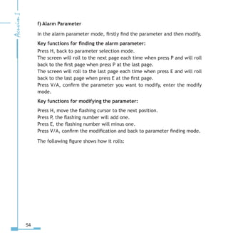
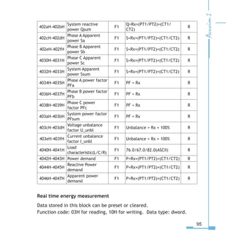
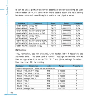
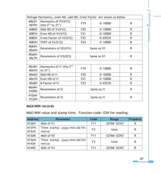
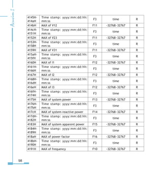
Copyright
©
2007 V1.2
This manual may not be reproduced in whole or in part by any means, without
the expressed written consent of Accuenergy.
The information contained in this document is believed to be accurate at the
time of publication, however, Accuenergy assumes no responsibility for any
errors which may appear here and reserves the right to make changes without
notice. Please ask the local representative for latest product specifications
before ordering.
I
Please read this manual carefully before doing installation, operation and
maintenance of Acuvim II meter.
Following symbols are used in this user’s manual and on Acuvim II meter to
alert the dangerous or to prompt in the operating or set process.
Dangerous symbol, Failure to observe the information may result in
injury or death.
Alert symbol, Alert the potential dangerous. Observe the
information after the symbol to avoid possible injury or death.
This mark is on product for UL Listed product
Installation and maintenance of the Acuvim II meter should only be performed
by qualified, competent personnel that have appropriate training and
experience with high voltage and current device.
This document is not fit for people without adequate experience and training.
Accuenergy is not liable for any problems occurring under proper operation.
II
Chapter 1 Introduction-------------------------------------------------------------------1
1.1 The Purpose of Acuvim II--------------------------------------------------2
1.2 The Application Area of Acuvim II---------------------------------------3
1.3 The Function of Acuvim II-------------------------------------------------3
Chapter 2 Installation-------------------------------------------------------------------5
2.1 Appearance and Dimensions--------------------------------------------8
2.2 Installation Method------------------------------------------------------9
2.3 Wiring of Acuvim II-------------------------------------------------------11
Chapter 3 Meter Operation and Parameter Setting---------------------------------27
3.1 Display Panel and Keys---------------------------------------------------28
3.2 Metering Data-------------------------------------------------------------31
3.3 Statistics Data-------------------------------------------------------------34
3.4 Demand Data--------------------------------------------------------------36
3.5 Harmonic Data------------------------------------------------------------36
3.6 Expanded I/O Module Data----------------------------------------------38
3.7 Parameter Setting Mode-------------------------------------------------42
3.8 Page recovery Function--------------------------------------------------56
Chapter 4 Function and Software-----------------------------------------------------57
4.1 Basic Analog Measurements---------------------------------------------58
4.2 Max/Min--------------------------------------------------------------------61
4.3 Harmonics and Power Quality Analysis--------------------------------62
4.4 Over-Range Alarming-----------------------------------------------------63
4.5 Extended I/O Module----------------------------------------------------72
4.6 Extended Communication Block---------------------------------------72
Chapter 5 Function and Software-----------------------------------------------------73
III
Content
5.1 Introducing Modbus Protocol--------------------------------------------74
5.2 Format of Communication----------------------------------------------77
5.3 Data Address Table and Application Details of Acuvim II-----------82
Appendix--------------------------------------------------------------------------------107
Appendix A Technical data and specifications--------------------------------------108
Appendix B Ordering Information----------------------------------------------------111
Appendix C Revision History----------------------------------------------------------112
IV
Starting!
Congratulations!
You have received an advanced, versatile, multifunction power meter, also
known as a Remote terminal unit (RTU), which will greatly benefit your power
system.
When you open the package, you will find the following items
1. Acuvim II meter          1
2. Pluggable Terminal         3
3. Installation clips          4
4. User’s operation manual	   1
5. Maintenance guarantee card	   1
Please read this manual carefully before operating or setting the Acuvim II
meter to avoid unnecessary trouble. You can read part of this manual depends
on how you use the Acuvim II meter.
Chapter 1 helps you to understand the fundamental function, specification and
application area of Acuvim II.
Chapter 2 describes detailed installation and wiring of Acuvim II.
Chapter 3 describes the data display and parameter setting method.
Chapter 4 outlines the functions of Acuvim II and the way to use them.
Chapter 5 gives the address table of Acuvim II.
Appendix lists the technical data and specifications and ordering information.
V
VI
1
Chapter 1 Introduction
The Purpose of Acuvim II
The Application Area of Acuvim II
The Functions of Acuvim II
1.1 The Purpose of Acuvim II
Powerful Multifunction Power Meter
Acuvim II Multifunction digital power meter is designed using modern
MCU and DSP technology. It integrates three-phase energy measuring
and displaying, energy accumulating, power quality analysis, malfunction
alarming and network communication. Large and vivid LCD meets your
visual requirement greatly. Graceful and high-lighted back light makes
it easy to check the measuring data. Simple HMI interface makes it easy
to master. Multi-row displaying lets you observe various data without
touching any keys.
Ideal Choice for Electric Automation SCADA System
Acuvim II can be used to replace all traditional electric meters. It also
can be used as Remote Terminal Unit (RTU) for monitoring and controlling
in a SCADA system. All the measured data is available via digital RS485
communication ports running the ModbusTM
protocol.
Energy Management
Acuvim II can measure bidirectional four quadrants kWh and kvarh. It
can provide maximum/minimum energy data and energy demand data.
With the help of master software, you can easily know how the load and
energy are running. It automatically gives you all kinds of measurement
tables as well.
Remote Power Control
The main function of Acuvim II is measuring, and it also has some flexible
I/O functions, which make the meter very useable as a distributed RTU
(metering, monitoring, remote controlling in one unit).
Power Quality Analysis
With the help of powerful digital signal processing technology, the Acuvim
II intelligent power meter can be used as an online power quality analysis
instrument. It can simultaneously and continuously give out the analysis
results such as THD of voltage and current, harmonics up to 31st order
and unbalance factor of voltage and current, etc.
1.2 The Application Area of Acuvim II
Power Distribution Automation    Intelligent Electric Switch Gear
Industry Automation        Building Automation
Energy Management System     Substation Automation
Resident district power monitoring
1.3 The Function of Acuvim II
Multifunction, High Accuracy
Acuvim II Multifunction Intelligent power meter is powerful in data
collecting and processing. It can not only measure up to several decades
of power parameters, but also do demand metering, harmonic analysis,
statistics of max/min, over range alarming, energy accumulating etc.
Accuracy of Voltage and Current is 0.2%, True-RMS.
Accuracy of Power and Energy is 0.5%, four quadrants metering.
Small Size and Easy Installation
Acuvim II can be installed using a standard ANSI C39.1 (4” Round) or an
IEC 92mm DIN (Square) form. With the 51mm depth after mounting, the
Acuvim II can be installed in a small cabin. The fixing clips are used for
easy installation and remove.
Easy to Use
With a large high density LCD screen, the display of the Acuvim II is easy
to read and use. All the measuring data and setting parameters can
be accessed by using panel keys or a communication port. The setting
parameters are protected in EEPROM, which will maintain its content
after the meter is powered off. With the backlight of the LCD, the
display can be easily read in a dim environment. The back light “on”
time is selectable.
Multiple Wiring Modes
The Acuvim II can easily be used in high voltage, low voltage, three
phase three wires, three phase four wires and single phase system using
approximate wiring.
High safety, high stability
Acuvim II was designed according to industrial standards. It can run
stably under high power disturbance condition as it has passed EMC and
Safety test according to IEC standards and UL certification.
5
Chapter 2 Installation
Appearance and Dimensions
Installation Method
Wiring of Acuvim II
Considerations When Installing Meters
 Installation of the Meter must be performed by only qualified personnel
who follow standard safety precautions during all procedures. Those
personnel should have appropriate training and experience with high
voltage devices. Appropriate safety gloves, safety glasses and protective
clothing are recommended.
 During normal operation of the Meter, dangerous voltages flow through
many parts of the meter, including: Terminals and any connected CTs
(Current Transformers) and PTs (Potential Transformers), all I/O Modules
(Inputs and Outputs) and their circuits. All Primary and Secondary circuits
can, at times, produce lethal voltages and currents. Avoid contact with any
current-carrying surfaces.
 Do not use the meter or any I/O Output Device for primary protection or
in an energy-limiting capacity. The meter can only be used as secondary
protection. Do not use the meter for applications where failure of the meter
may cause harm or death. Do not use the meter for any application where
there may be a risk of fire.
 All meter terminals should be inaccessible after installation.
 Do not apply more than the maximum voltage the meter or any attached
device can withstand. Refer to meter and/or device labels and to the
Specifications for all devices before applying voltages. Do not HIPOT/
Dielectric test any Outputs, Inputs or Communications terminals.
 ACCUENERGY recommends the use of Shorting Blocks and Fuses for
voltage leads and power supply to prevent hazardous voltage conditions
or damage to CTs, if the meter needs to be removed from service. CT
grounding is optional.
 ACCUENERGY recommends use dry cloth to wipe the meter.
NOTE: IF THE EQUIPMENT IS USED IN A MANNER NOT
SPECIFIED BY THE MANUFACTURER, THE PROTECTION
PROVIDED BY THE EQUIPMENT MAY BE IMPAIRED.
NOTE: THERE IS NO REQUIRED PREVENTIVE MAINTENANCE OR
INSPECTION NECESSARY FOR SAFETY. HOWEVER, ANY REPAIR OR
MAINTENANCE SHOULD BE PERFORMED BY THE FACTORY.
DISCONNECT DEVICE: The following part is considered the
equipment disconnect device.
A SWITCH OR CIRCUIT-BREAKER SHALL BE INCLUDED IN THE END-
USE EQUIPMENT OR BUILDING INSTALLATION. THE SWITCH SHALL
BE IN CLOSE PROXIMITY TO THE EQUIPMENT AND WITHIN EASY
REACH OF THE OPERATOR. THE SWITCH SHALL BE MARKED AS THE
DISCONNECTING DEVICE FOR THE EQUIPMENT.
The installation method is introduced in this chapter. Please read this
chapter carefully before beginning installation work.
2.1 Appearance and Dimensions
Appearance
Fig 2.1 Appearance of Acuvim II
Part Name Description
1. Enclosure
The Acuvim II enclosures are made of high strength
anti-combustible engineering plastic
2. Front Casing After the installation, this part is before the panel.
3. LCD Display Large bright white backlight LCD Display
4. Key Four keys are used to select display and set
5. Voltage Input Terminals Used for Voltage input
6. Current input Terminals Used for Current input
7. Power Supply Terminals Used for Supply input
8. Communication Termi-
nals
Communication output
9. Installation Clip The clips are used for fixing the meter to the panel
Table 2.1 Part name of Acuvim II
① ②
③
④
⑤
⑥
⑦⑧
⑨
Dimensions (mm)
            Front view 	    Side view
Fig 2.2 Dimensions
2.2 Installation Method
Environmental
Before installation, please check the environment temperature and
humidity to ensure the Acuvim II meter is being placed where optimum
performance will occur.
Temperature
Operation: -25℃ to 70℃.
Storage: -40℃ to 85℃
Humidity
5% to 95% non-condensing.
Acuvim II meter should be installed in dry and dust free environment and
avoid heat, radiation and high electrical noise source.
10
Installation Steps
Acuvim II can be installed using a standard ANSI C39.1 (4” Round) or an
IEC 92mm DIN (Square) form.
1. Firstly, cut a square hole or round hole on the panel of the switch
gear.
The cutting size is shown in fig 2.3. The Unit is mm.
Fig 2.3 Panel Cutting
2. Secondly, remove the clips from the meter, and insert the meter into
the square hole from the front side.
Fig 2.4 Put the meter into the square hole
11
3. Finally, put clips back to the meter from the backside and push the
clip tightly so that the meter is fixed on the panel.
Fig 2.5 Use the clips to fix the meter on the panel
2.3 Wiring of Acuvim II
Terminal Strips
There are four terminal strips on the back of Acuvim II. The 1, 2 and 3
are used to represent each phase of three phase system. They have the
same meaning with A, B and C or R, S and T in three phase system.
12
Current Input Terminal Strip
Voltage Input Terminal Strip
Power Supply Terminal strip
Communication terminal strip
Fig 2-6. Terminal Strips of Acuvim II
  
V1 V V
10
VN
I11 I1 I1 I I1 I
1    5 !
Power Supply
111
N/–L/ +
1
Comm Port
A B S
1 15 1
13
Safety Earth Connection
Before doing the meter wiring connection, please
make sure that the switch gear has a safety Earth
system. Connect the meter safety earth terminal
to the switch gear safety earth system. The
following safety earth symbol is used in this user’
s manual.
         Fig 2-7 Safeth Earth Symbol
Auxiliary Power
The auxiliary power supply of the Acuvim II meter
is 100-415Vac (50/60Hz) or 100-300Vdc. The
meter’s typical power consumption is very little
so it can be supplied by an independent source or
by the line to be measured. A regulator or a UPS
should be used when the power supply undulates
too much. The terminals for the auxiliary power
supply are 11, 12 and 13 (L, N, and Ground). A
switch or circuit-breaker shall be included in
the building installation, and it shall be in close
proximity to the equipment and within easy reach
of the operator, and it shall be marked as the
disconnecting device for the equipment.
NOTE
M a k e s u r e t h e
a u x i l i a r y p o w e r
t e r m i n a l o f t h e
meter ground is
connected to the
s a f e t y E a r t h o f
switchgear.
DANEROUS
Only the qualified
personnel could do
the wire connection
work. Make sure
the power supply is
cut off and all the
wires are powerless.
Failure to observe it
may result in severe
injury or death.
NOTE
M a k e s u r e t h e
voltage of power
supply is the same
as what the meter
n e e d e d f o r i t s
auxiliary power.
14
Fig 2-8 Power supply
A fuse (typical 1A/250Vac) should be used in auxiliary power supply
loop. No. 13 terminal must be connected to the safety earth system
of switchgear. An isolated transformer or EMC filter should be used in
the auxiliary power supply loop if there is power quality problem in the
power supply.
         Fig 2-9 Power supply under noisy condition
Choice of wire of power supply could be AWG22-16 or 0.6-1.5mm2
.
Voltage Input
Input voltage of Acuvim II should be 400 LN/690 LL VAC rms(three
phases),400 LN VAC(single phase).
In high voltage system, a PT must be used. The secondary output of
the PT should be 100V or 120V typically. The accuracy of measurement
is related to the PT you select, so be careful! For the star system, the
NOTE
A filter should
b e u s e d i f
there is EMI
problem.
L
N
1A FUSE
Power Supply
Ground
11
1
1
Acuvim II
Ground
1A FUSE
Power Supply
Acuvim II
L
N
L
N
G
L
N
G
EMC Filter
1
1
11
15
primary rated voltage of PT is equal to or close to the phase voltage of
the system. For the delta system, it is the line voltage of the system. A
fuse (typical 1A/250Vac) should be used in voltage input loop. The wire
of voltage input could be AWG16-12 or 1.3-2.0mm2
.
Note: In no circumstance could the secondary of PT be shorted. The
secondary of PT should be well grounded at one end.
Current Input
In a practical engineering application, CTs should be installed in the
loop of measuring. Normally the secondary of CT is 5A. 1A is possible
in the ordering option. A CT of accuracy over 0.5% (rating over 3VA) is
recommended and it will influence the measuring accuracy. The wire
between CT and Acuvim II should be as short as possible. The length
of the wire may increase the error of the measurement. CTs must be
required if the rated current is over 5A.
The wire number of current input could be AWG15-10 or 1.5-2.5mm2
.
The CT loop should not be open circuit in any circumstance when the
power is on. There should not be any fuse or switch in the CT loop and
one end of the CT loop should be well connected to the ground.
Vn Connection
Vn is the reference point of Acuvim II voltage input. The lower is the
wire resistance the better is the accuracy. The wiring mode of Vn
depends greatly on the system wiring mode. Please refer to the wiring
diagram.
Three phase wiring diagram
Acuvim II can satisfy almost all kinds of three phase wiring diagram.
16
Please read this part carefully before you begin to do the wiring so that
you can choose a suitable wiring method for your power system.
The voltage and current input wiring mode can be set separately in the
meter parameter setting process. The voltage wiring mode could be
3-phase 4-line Wye (3LN), 3-phase 4-line 2PT Wye mode (2LN) and 3-phase
3-line open delta (2LL). The current input wiring mode could be 3CT,
2CT and 1CT. Any voltage mode could be group with one of the current
mode.
Voltage Input Wiring
3-Phase 4-Line Wye mode (3LN)
The 3-Phase 4-Line Wye mode is popularly used in low voltage electric
distribution power system. The power line can be connected to the
meter voltage input directly as in fig 2.10a. In the high voltage input
system, 3PT Wye mode is often used as in fig 2.10b. The voltage input
mode of the Acuvim II should be set 3LN for both voltage input wiring
mode.
Fig 2.10a 3LN direct connection
LINE
LOAD
V1
V
V
VN


10
A B C N
1A FUSE
Acuvim II
17
Fig 2.10b 3LN with 3PT
3-Phase 4-Line 2PT mode (2LN)
In some 3-Phase 4-Line Wye system, 2PT Wye mode is often used as in
fig2.11, where the 3 phases of power system is supposed to be balanced.
The voltage of V2 is calculated according to the V1 and V3. The voltage
input mode of the Acuvim II should be set 2LN for 2PT voltage input
wiring mode.
Fig 2.11 2LN with 2PTs
LINE
LOAD
V1
V
V


A B C N
10
1A FUSE
VN
Acuvim II
LINE
LOAD
V1
V
V
Acuvim II


A B C N
1A FUSE
10 VN
18
3-Phase 3-Line direct connection mode (3LL)
In a 3-Phase 3-Line system, power line A, B and C are connected to V1,
V2 and V3 directly. Vn is floated. The voltage input mode of the Acuvim
II should be set 3LL.
Fig 2.12 3LN 3-Phase 3-Line direct connection
3-Phase 3-Line open Delta Mode (2LL)
Open delta wiring mode is often used in high voltage system. V2 and
Vn are connected together in this mode. The voltage input mode of the
Acuvim II should be set 2LL for voltage input wiring mode.
Fig 2.13 2LL with 2PTs
LINE
LOAD
V1
V
V


A B C
10 Vn
1A FUSE
Acuvim II
LINE
LOAD
V1
V
V
VN
Acuvim II


10
A B C
1A FUSE
19
Current Input Wiring
3CT
All the current input of three phase system can be looked as 3CT one,
whether there are 2 CTs or 3 CTs in the input side. The current input
mode of the Acuvim II should be set 3CT for this current input wiring
mode.
Fig 2.14 3CTs a
Fig 2.15 3CTs b
LINE
LOAD
A B C
I115


I

 I1
I1
I
I1

Terminal block
1


5
Acuvim II
LINE
LOAD
A B C
I115


I

 I1
I1
I
I1

Terminal block
1


5
Acuvim II
20
2CT
The difference of the fig 2.16 and the fig.2.15 is that there is no current
input in the I21 and I22 terminals. The I2 value is calculated from
formula i1+i2+i3=0. The current input mode of the Acuvim II should be
set 2CT for this current input wiring mode.
Fig 2.16 2CTs
1CT
If it is a three phase balance system, 1 CT connection method can be
used. All the other two current are calculated according to the balance
supposing.
Fig 2.17 1CT
LINE
LOAD
A B C
I115


I

 I1
I1
I
I1

Terminal block
1


5
Acuvim II
LINE
LOAD
A B C
I115


I

 I1
I1
I
I1

Terminal block
1


5
Acuvim II
21
Frequently used wiring method
The voltage and current wiring method are put together in one drawing.
The Acuvim II meter will display normally only that the setting of the
meter is assorted with the wiring of the voltage and current input.
1. 3LN, 3CT with 3 CTs
Fig 2.18 3LN, 3CT
2. 3LN, 3CT with 2 CTs
Fig 2.19 3LN, 3CT with 2CTs
N
LINE
LOAD
A B C
I115


I

 I1
I1
I
I1

Terminal block
1


5
V1VV
10
1A FUSE
VN
Acuvim II
N
LINE
LOAD
A B C
I115


I

 I1
I1
I
I1

Terminal block
1


5
V1VVVN
10
1A FUSE
Acuvim II
22
3. 2LN, 2CT
Fig 2.20 2LN, 2CT
4. 2LN, 1CT
Fig 2.21 2LN, 1CT
LOAD
I115


I

 I1
I1
I
I1

Terminal block
1


5
V1VV
10
1A FUSE
LINE
A B C N
VN
Acuvim II
LOAD
I115


I

 I1
I1
I
I1

Terminal block
1


5
V1VVVN
10
1A FUSE
LINE
A B C N
Acuvim II
23
5. 2LL, 3CT
Fig 2.22 2LL, 3CT
6. 2LL, 2CT
Fig 2.23 2LL, 2CT
LOAD
I115


I

 I1
I1
I
I1

Terminal block
1


5
V1VVVN
10
1A FUSE
LINE
A B C
Acuvim II
LOAD
I115


I

 I1
I1
I
I1

Terminal block
1


5
V1VVVN
10
1A FUSE
LINE
A B C
Acuvim II
24
7. 2LL, 1CT
Fig 2.24 2LL, 1CT
8. Single Phase 2 Line (Wiring mode setting 3LN, 3CT)
Fig 2.25 Single phase 2Lines
LOAD
I115


I

 I1
I1
I
I1

Terminal block
1


5
V1VVVN
10
1A FUSE
LINE
A B C
Acuvim II
N
LINE
LOAD
A
I115


I

 I1
I1
I
I1

Terminal block
1


5
V1VVVN
10
1A FUSE
Acuvim II
25
9. Single Phase 3 Line (Wiring mode setting 3LN, 3CT)
Fig 2.26 Single phase 3Lines
Communication
The communication port and protocol of Acuvim II are RS485 and Modbus-
RTU. The terminals of communication are A, B, and S (14, 15, 16). A is
differential signal +, B is differential signal - and S is connected to shield
of twisted pair cable. Please use good quality shielded twisted pair
cable, AWG22 (0.5mm2
) or higher. The overall length of the RS485 cable
connecting all devices should not exceed 1200m (4000ft). Acuvim II is
used as a slave device of masters like PC, PLC, data collector or RTU.
If the master does not have RS485 communication port, a converter has
to be used. Normally a RS232/RS485 or USB/RS485 is adopted. The
topology of RS485 net can be line, circle and star.
For the high quality communication, good quality shielded twisted pair of
cable AWG22 (0.5mm2
) or higher is very important.
N
LINE
LOAD
A
I115


I

 I1
I1
I
I1

Terminal block
1


5
V1VVVN
10
1A FUSE
B
Acuvim II
26
The shield of each segment of the RS485 cable must be connected to the
ground at one end only.
Every A(+) should be connected to A(+), B(-) to B(-), or it will influence
the network, or even damage the communication interface.
The connection topology should avoid “T” type which means there is a
new branch and it does not begin from the beginning point.
Keep communication cables away as much as possible from sources of
electrical noise.
When many devices are connected to the same long communication
line, an antireflection resistor of 120Ω-300Ω is preferred which will be
connected to A and B at the end of the line.
Use RS232/RS485 or USB/RS485 converter with optical isolated output
and surge protection.
27
Chapter 3 Meter Operation and Parameter Setting
Display Panel and Keys
Metering Data
Statistics Data
Demand Data
Harmonic Data
Expanded I/O Module Data
Parameters Setting
28
Detailed human-machine interface of the meter will be described in
this chapter, including how to get the metering data and how to do the
parameter setting.
3.1 Display Panel and Keys
There are one display panel and four keys in the front of Acuvim II. All
the display segments are illustrated in fig 3.1. Users should note that all
the segments will not display in a single page when normally used.
1
2
3
4
5
6
7
8
9
10
11
12
13 14 15 16
17
Fig3.1 All Display Segments
SN Display Description
1 Display mode indication
It shows the topic of the display area, “Meter”
for real-time measurement; “Max/Min” for
statistic data; “Demand” for power demand
data; “Harmonic” for harmonic data; “Setting”
for parameters setting; “Digital I/O” for
expended IO module data.
29
2
Four lines of “ ” letters in
the metering area
Main Display Area: display metering data
such as voltage, current, power, power
factor, frequency, imbalance, phase angle,
etc; display statistics such as maximum and
minimum; display demand data; display
settings and display expanded I/O data.
3
four “ ” and five “ ”
letters
Display energy data and real-time clock. Also
used for the setting mode and digital I/O
mode display.
4 three “ ” letters
Item label: “U” for voltage; “I” for current;
“P” for active power; “Q” for reactive power;
“S” for apparent power; “PF” for power
factor; “F” for frequency; “∠” for phase
angles; “DMD” for demand; display setting
page number; display expanded IO module
type for “Mxx”.
5
Unbalance、THD、TDD、
MAX、MIN
Item Label: “Unbalance” for imbalance of
the voltage and current; “THD” for total
harmonics distortion; “TDD” for total demand
distortion; “MAX” for maximum and “MIN” for
minimum
6 Load rate
Display the percentage of the load current to
the nominal current.
7
Four quadrant label
and load type label
: the quadrant of the system power
Inductor label: inductive load
Capacitor label: capacitive load
8 1-2, 2-3, 3-1, avg, N
1, 2, 3 for 3 phase A, B, C; 1-2, 2-3, 3-1 for 3
phase line-to-line AB, BC, CA; avg for average
and N for neutral.
9
Energy label: Imp, Total, Net,
Exp
Imp: consumption energy;
Exp: generation energy;
Total: absolute sum of Imp and Exp energy
Net: algebraic sum of Imp and Exp energy
30
10 Unit
voltage: V,kV; current: A,kA;active
power: kW, MW; reactive power: kvar, Mvar;
apparent power: kVA, MVA; frequency: Hz;
active energy: kWh; reactive energy: kVarh;
apparent energy: kVAh; percentage: %; phase
angle: °
11 Communication label
No label: no communication
One label: inquiry
Two labels: inquiry and answer
12
Energy pulse output indicator No label: no pulse output
With label: pulse output
13
Expanded I/O module
indicator
M1: one AXM-IO1 connected
M1x2: two AXM-IO1 connected
None: no AXM-IO1 connected
M2: one AXM-IO2 connected
M2x2: two AXM-IO2 connected
None: no AXM-IO2 connected
M3: one AXM-IO3 connected
M3x2: two AXM-IO3 connected
None: no AXM-IO3 connected
14
Profibus module indicator None: Profibus module not connected
illume: Profibus module connected
15
Ethernet module indicator None: Ethernet module not connected
illume: Ethernet module connected
16 reserved
17 time label Time display in energy area
There are four keys in the front panel, label as H, P, E and V/A from
left to right. Use these four keys to read metering data and set the
parameters.
Note: If the backlight is off before you press any keys, it will become on
and no other functions will be activated.
31
3.2 Metering Data
Press H and V/A simultaneously will activate the display mode selection
and the cursor will flash. Press P or E to move the cursor right or left to
“Meter”, then press V/A, and you will enter the metering mode.
In the metering mode, meter displays measurements such as voltage,
current, power, power factor, phase angle, imbalance, etc.
a) Voltage and Current:
Press V/A to read voltage and current in the metering area. The screen
will roll to the next page as you press V/A each time. It will go back to
the first screen if you press V/A at the last screen.
The following figure shows how it rolls:
Note: When the meter is set to “2LL” or “3LL”, there is no phase voltage
and neutral current display. So only the third and fourth screens will be
displayed.
Three phase Voltage
 avg
Three phase Current
 In
Line Voltage  avg
Three phase Current
 avg
V/A
V/A
V/A
V/A
V/A
32
b) Power, Power Factor and Frequency:
Press P, display power related data.
The screen will roll to the next page as you press P each time. It will go
back to the first screen if you press P at the last screen.
The following figure shows how it rolls:
Note: When the meter is set to “2LL” or “3LL”, only the fifth and sixth
screens will be displayed.
c) Phase Angles and Imbalance:
Press H, display phase angles and imbalance data. The screen will roll to
the next page as you press H each time. It will go back to the first screen
Three phase power
P
Three phase
reactive power
P
Three phase
apparent power
P
Three phase PF
P
System power
P
System power factor
 frequency
P
P
33
if you press H at the last screen.
The following figure shows how it rolls:
Note: Voltage stands for line-to-line voltage when the wiring setting is
“2LL” or “3LL” and for line-to-neutral voltage when other wiring settings.
d) Energy:
Press E key, display energy and real time clock. The screen will roll to
the next page as you press E each time. It will go back to the first screen
if you press E at the last screen.
Acuvim II meter can be set to record primary power or secondary power.
The unit of power is kWh for active power, kvarh for reactive power and
kVAh for apparent power. The running time begins to take record at
the time when the meter is turned on, with the accuracy of 0.01H and
is stored in the non-volatile memory. It can be reset via communication
and panel.
The following figure shows how it rolls:
Unbalance factor
Voltage phase
angle
Current phase
angle
H
H
H
H
34
3.3 Statistics Data
Press H and V/A simultaneously will activate the display mode selection
and the cursor will flash. Press P or E to move the cursor right or left to
“Max/Min”, then press V/A, and you will enter the statistics data mode.
In the statistics data mode, meter displays the maximum values and
minimum values for voltage, current, power, power factor, imbalance,
demand, THD, etc. User should note that there are no time label
displays and they can only be accessed through communication.
Press H, no functions.
Consumption energy
E
Generation energy
E
Total energy
E
Net energy
E
The absorption
reactive energy
E
The generation
reactive energy
E
Total reactive
energy
E
Net reactive energy
E
E
E
Date Format:
mm:dd:yyyy
E
Time Format:
hh:mm:ss
E
Meter running time
E
Total electrical
degree
35
Press P, screen will roll to the next page, and will roll back to the first
screen when pressed at the last page.
Press E, screen will roll back to the last page, and will roll back to the
last screen when pressed at the first page.
V/A is used for switch the display between maximum and minimum. For
example, if the maximum of the phase voltage is displayed, press V/A,
and the display will switch to minimum of the phase voltage. If you press
again, it will switch back to the display of the maximum. Each time you
press V/A, it switches.
The following figure shows how it rolls:
Note:
i) The figure shows the rolling sequence for using key P. If using E
key for rolling page, the sequence will reverse.
Max value of phase
voltage
P
Max value of the line
to line voltage
P
Max value of current
P
Max value of power
P
Max value of power
factor  frequency
P
Max value of
unbalance factor
P
P
Max value of the
demand
Max value of voltage
harmonics
Max value of current
harmonics
P
P
36
ii) When meter is set to “2LL” or “3LL”, the first screen will not be
displayed.
3.4 Demand Data
Press H and V/A simultaneously will activate the display mode selection
and the cursor will flash. Press P or E to move the cursor right or left to
“Demand”, then press V/A, and you will enter the demand data mode.
In the demand data mode, there is only one page, displaying the demand
of active power, reactive power and apparent power.
As shown in the figure, system active power demand is 3.285kW, system
reactive power demand is 0 kvar, system apparent power demand is 3.285
kVA.
3.5 Harmonic Data
Press H and V/A simultaneously will activate the display mode selection
and the cursor will flash. Press P or E to move the cursor right or left to
“Harmonic”, then press V/A, and you will enter the harmonic data mode.
In the harmonic data mode, meter displays the harmonic ratio of voltage
and current, THD, odd HD, even HD, THFF, CF and KF.
37
a) Power Quality Data:
Press H, display power quality data. It rolls to the next page when press
H each time and roll back to the first page when press H at the last page.
Press P, no function.
Press E, no function.
Press V/A, switch to the display of harmonic ratio data.
b) Harmonic Ratio Data
Press H, switch to the display of power quality data.
The harmonic order will add by one when press P each time and will back
to 2nd when press P at the 31st harmonics.
THD of voltage 
avg
Odd harmonic
distortion of voltage
H
Even harmonic
distortion of voltage
H
THFF
H
Crest factor of
Voltage
H
THD of current 
avg
H
Odd harmonic
distortion of current
Even harmonic
distortion of current
The “K”factor of
current
H
H
H
H
38
The harmonic order will minus by one when press E each time and will
back to 31 when press E at the 2nd harmonics.
Press V/A, switch display between voltage harmonics and current
harmonics.
The following figure shows how it rolls:
Note: The figure shows the rolling sequence for using key P. If using E
key for rolling page, the sequence will reverse.
3.6 Expanded I/O Module Data
Press H and V/A simultaneously will activate the display mode selection
and the cursor will flash. Press P or E to move the cursor right or left
to “Digital I/O”, then press V/A, and you will enter the expanded I/O
module data mode.
The nd harmonic
ratio of voltage
The rd harmonic
ratio of voltage
P
The th harmonic
ratio of voltage
P
1st harmonic ratio
of voltage
P
The nd harmonic
ratio of current
The rd harmonic
ratio of current
P
The th harmonic
ratio of current
P
1st harmonic ratio
ofcurrent
P
V/A
V/A
V/A
V/A
P P
V/A
39
In the expanded I/O module data mode, meter displays the data from
expanded I/O modules, such as DI status, pulse counter number, Relay
status, Analog Output, and Analog Input, etc.
In the expanded I/O module data mode, first page is the module selection
and you can choose any module as you wish. If no expanded I/O module
is connected, it will display “NO IO”.
a) Module Selection:
Press H, no function.
Press P, move the cursor downwards. When the cursor is at the bottom,
press P will move the cursor to the top. If there is only one module
connected, press P will have no effect.
Press E, move the cursor upwards. When the cursor is at the top, press
E will move the cursor to the bottom. If there is only one module
connected, press E will have no effect.
Press V/A, select the module and enter the I/O module data selection
mode.
40
As shown in the figure, three modules are connected, AXM-IO11, AXM-
IO21, AXM-IO31, which are indicated by M11, M21, M31 respectively. The
cursor points to M21, which indicates that AXM-IO21 is chosen now.
b) I/O Module Data Selection
Press H, back to module selection mode.
Press P, move the cursor downwards. When the cursor is at the bottom,
press P will move the cursor to the top. Please note that there are 3
parameters for AXM-IO1, 3 parameters for AXM-IO2 and 4 parameters for
AXM-IO3.
Press E, move the cursor upwards. When the cursor is at the top, press E
will move the cursor to the bottom.
Press V/A, select the parameter and enter the display of the data.
c) I/O module data display
Press H, back to I/O module data selection mode.
The screen will roll to the next page each time when press P and will roll
back to the first page when press P at the last page. If only one page
exist, press P will have no effect.
The screen will roll to the last page each time when press E and will roll
back to the last page when press E at the first page. If only one page
exist, press E will have no effect.
Press V/A, no function.
The following figure shows how it rolls:
41
IO: M21 or M
M1(M): AO
V/A
M1(M): pulse
count
M1/M
M1(M): DI
V/A
M1(M): DI1-
M1(M): AO1、AO2 output
M1(M):Counter 1
M1(M):Counter 
M1(M):Counter 
M1(M):Counter 
HH
V/A
H
P
P
P
P
V/A
H
IO: M11 or M1 M11(M1): RO
V/A
M11(M1): pluse
count
M11/M1
M11(M1): DI
V/A
V/A
M11(M1): DI1-
M11(M1): DI-
M11(M1): RO1、RO
M11(M1): Counter 1
M11(M1): Counter 
M11(M1): Counter 
M11(M1): Counter 
M11(M1): Counter 5
M11(M1): Counter 
H
P P
HH
V/A
H
P
P
P
P
P
P
42
Note: The figure shows the rolling sequence for using key P. If using E key
for rolling page, the sequence will reverse.
3.7 Parameter Setting Mode
Press H and V/A simultaneously will activate the display mode selection
and the cursor will flash. Press P or E to move the cursor right or left to
“Setting”, then press V/A key and you will enter the parameter setting
mode.
In the parameter setting mode, parameters, such as system parameters,
expanded I/O module parameters, alarm parameters and Ethernet
module parameters, can be read and modified.
a) Password Inquiry:
IO: M31 or M M1(M):RO
V/A
M1(M): pulse
count
Module: M1/M
M1(M):DI
V/A
M1(M): DI1-
M1(M): RO1、RO
M1(M): Counter1
M1(M): Counter
M1(M): Counter
M1(M): Counter
HH
V/A
H
P
P
P
P
V/A
H
M1(M):AI M1(M):AI1、AI2 input
V/A
H
43
Entering the parameter setting mode, firstly, the device address will
appear for several seconds and then go to the password inquiry page.
“Password” is the key to the parameter setting mode and only valid
password will help you to go through and use the meter setting. This
function helps to prevent the mis-operation and unauthorized people
to modify the meter parameters. There are 4 digits of password in the
meter, which can be set from “0000” to “9999” with the default value
of “0000”. User should input the right password and press V/A key to go
through to the parameter selection page; otherwise it will stay at the
password inquiry page.
The following figure shows the password inquiry page.
Key functions when inputting password:
Press H, move the flashing cursor to the next position.
Press P, the flashing number will add one.
Press E, the flashing number will minus one.
Press V/A, confirm the password.
b) Parameter Selection Mode
In the parameter selection mode, there are four parameters for choices:
system, expanded I/O module, Ethernet module and alarms.
44
Press H, no function.
Press P, move the cursor downwards. When the cursor is at the bottom,
press P will move the cursor to the top.
Press E, move the cursor upwards. When the cursor is at the top, press E
will move the cursor to the bottom.
Press V/A, choose the parameter and enter the parameter modify mode.
The figure shows the parameter selection page. “SYS” stands for system
parameter, “I/O” stands for expanded I/O module parameter, “NET”
stands for Ethernet module parameter and “ALM” stands for alarm
parameter. As shown in the figure, the cursor points to the “SYS”, which
means system parameter is selected.
c) System Parameter Setting
In the system parameter setting mode, firstly find the parameter and
then modify.
Key functions for finding the parameter:
Press H, back to parameter selection mode.
45
The screen will roll to the next page each time when press P and will roll
back to the first page when press P at the last page.
The screen will roll to the last page each time when press E and will roll
back to the last page when press E at the first page.
Press V/A, confirm the parameter you want to modify, enter the modify
mode.
Key functions for modifying the parameter:
Press H, move the flashing cursor to the next position.
Press P, the flashing number will add one.
Press E, the flashing number will minus one.
Press V/A, confirm the modification and back to parameter finding mode.
The following figure shows how it rolls:
46
S1:demand clear
P
Yes:clear; No:not clear
S01: Meter address
S0: Baud rate
S0: Voltage wiring
Any integer from 1~
Select form 00,100, 00,00,00,100,38400
bps
Voltage wiring mode can be one of “LN”, “LN”,
“LL”, “LL”
S0: Current wiring
Current wiring mode can be one of “ CT”, “1CT”,
“CT”
S05: PT1 PT1: primary nominal value of PT, range from 50.0V~500,000.0V
S0: PT
PT: secondary nominal value of PT, range from 50.0V~00.0V
If no PT used , set PT1 and PT2 as the nominal voltage of the
meter.
S0: CT1 CT1: primary value of CT, range from 1A~50000A;
S0: CT CT: secondary value of CT, choose from 1A or 5A;
S0: pulse constant
for active energy
S10: pulse constant
for reactive energy
Indicates the kWh for one pulse . Range from 1~6000 and the unit
is 0.1kWh/pulse
Indicates the kvarh for one pulse . Range from 1~6000 and the
unit is 0.1kvarh/pulse
P
P
P
P
P
P
P
P
P
S11:backlight time
P The “on” time can be set from 0 to 120 Minute. The backlight will
always be “on” if the setting value is 0. If it is other value , it means
after that long time it will goes off if no key has been pressed . It
will be “on” whenever you press any key if it is “off” .。
S1:demand
calculation method
P
1: sliding block, : thermal
S1:demand
window
P
Range from 1~30 minutes
SYS setting
V/A
47
S15:max/min clear
P
S1:run hour clear
P
S1:I1 direction
P
S1:I2 direction
P
S1:I3 direction
P
To adjust polarity of current , the three current’s direction can be set
as “Negative” which means reversing 180 degrees and “Positive”
which means normal.
S0:VAR /PF
Convention
P
0: IEC, 1: IEEE
S1:energy clear
P
S:energy mode
P
Fund: fundamental; Full: full wave
S:calculation
method of reactive
power
P
0: true
1: generalized
S:energy type
P
Pre: primary energy;
Sec: secondary energy
S5:pulse counter
clear
P
S:password
P
Last page of the system parameter setting . Set the password in this
page and make sure to remember the new password , or you may
not use the meter properly .
S:Profibus
address
P
Any integer from 0-1
22
PSQ −=
P
S:SOE enable
Yes:clear; No:not clear
To clear the Max and Min value does not mean write 0 to all the
registers, it will copy the metering value to the statistic registers
and start a new statistic period .
Range from 0-.
0: not clear; 1: AXM-IO11 clear; : AXM-IO21 clear; : AXM-IO31
clear; : AXM-IO12 clear; 5 AXM-IO22 clear; : AXM-IO32 clear;
Range from 0-.
0: disable; 1: AXM-IO11 enable; : AXM-IO21 enable; : AXM-IO31
enable; : AXM-IO12 enable; 5 AXM-IO22 enable; : AXM-IO32
enable;
S:Basic
Parameter mode
P
Pre: primary energy;
Sec: secondary energy
48
Note: The figure shows the rolling sequence for using key P. If using E
key for rolling page, the sequence will reverse.
d) Expanded I/O Module Parameter
In the expanded I/O module parameter mode, firstly choose the module
to be modified and then make the modification. If no expanded I/O
module is connected, it will display “NO IO”. At this time, Press H to go
back to the parameter selection mode and other keys have no effect.
Key functions for I/O module selection:
Press H, back to parameter selection mode.
Press P, move the cursor downwards. When the cursor is at the bottom,
press P will move the cursor to the top. If there is only one module
connected, press P will have no effect.
Press E, move the cursor upwards. When the cursor is at the top, press
E will move the cursor to the bottom. If there is only one module
connected, press E will have no effect.
Press V/A, select the module and enter the I/O module parameter finding
mode.
Key functions for finding the I/O module parameter:
Press H, back to I/O module selection mode.
The screen will roll to the next page each time when press P and will roll
back to the first page when press P at the last page.
The screen will roll to the last page each time when press E and will roll
back to the last page when press E at the first page.
Press V/A, confirm the parameter you want to modify, enter the modify
mode.
49
Key functions for modifying the parameter:
Press H, move the flashing cursor to the next position.
Press P, the flashing number will add one.
Press E, the flashing number will minus one.
Press V/A, confirm the modification and back to parameter finding mode.
The following table shows how it rolls:
I/O:M11/M12
Module
M11(M12):pulse
counter enable
DI of AXM-IO1 can be used as the pulse counter, each DI function is
correspond to one bit of a 8-bit register. The correspondence bit of
0 means that the DI works as the digital status input and the
correspondence bit of 1 means that the DI works as the pulse
counter. For example, if the setting value is 000001, it means that
DI1 is set as the pulse counter and other DI works as he digital
status input.P
V/A
M11(M12):pulse
constant
If the DI works as the pulse counter, then when pulse number
counted by DI reach the pulse constant, the pulse counter will add
by one, which means that the real pulse number equals the number
of pulse counter times the pulse constant.P
M11(M12):relay
output mode
Relays of AXM-IO1 can be used as alarm output or control output.
ALM:alarm output; CTRL:control output
P
M11(M12):realy
working pattern
When set as the control output, the relays have the working pattern
of latch mode or pulse mode.
LATCH:latch mode; PUL:pulse mode
P
M11(M12):relay
output pulse width
If the relay work pattern is pulse mode, it means that the relay will
close for a specified period and then open automatically. The pulse
width range is 50~3000 ms.
Module M11/M12
50
I/O: M1/M22
Module
M1(M): pulse
counter enable
P
V/A
M1(M): pulse
constant
P
M1(M): DO
output mode
P
M1(M): DO pulse
width
P
M1(M): DO1
output type
Module M 1/M
P
M1(M): DO2
output type
P
M1(M): AO type
P
M1(M): AO1
transforming parameter
P
M1(M): AO2
transforming parameter
DI of AXM-IO2 can be used as the pulse counter, each DI function
is correspond to one bit of a 8-bit register. The correspondence
bit of 0 means that the DI works as the digital status input and
the correspondence bit of 1 means that the DI works as the pulse
counter. For example, if the setting value is 0001, it means that DI1 is
set as the pulse counter and other DI works as he digital status input.
If the DI works as the pulse counter, then when pulse number
counted by DI reach the pulse constant, the pulse counter will add by
one, which means that the real pulse number equals the number of
pulse counter times the pulse constant.
DO of AXM-IO1 can be used as alarm output or energy pulse output.
ALM: alarm output; PUL: energy pulse output
Range from 20-1000 ms
Choose the output energy type for DO1. Range from 0-4. 0: no
output; 1: import active energy; 2: export active power; 3: import
reactive energy; 4: export reactive energy.
The same as DO1. if the DO is set as the alarm output, this
parameter will have no effect.
Range: 0~3. 0: 0-20mA; 1: 4-20mA; 2: 0-5V; 3: 1-5V
Range: 0~29, See Chapter 5
51
Note: The figure shows the rolling sequence for using key P. If using E
key for rolling page, the sequence will reverse.
I/O:M1/M32
Module
M1(M):pulse
counter enable
P
V/A
M1(M):pulse
constant
P
M1(M):relay
output mode
P
M1(M):relay
working pattern
P
M1(M):relay
output pulse width
Module M1/M
P
M1(M):AI type Range: 0~. 0:0-0mA; 1:-0mA; :0-5V; :1-5V
If the DI works as the pulse counter, then when pulse number
counted by DI reach the pulse constant, the pulse counter will add by
one, which means that the real pulse number equals the number of
pulse counter times the pulse constant.
DI of AXM-IO can be used as the pulse counter, each DI function is
correspond to one bit of a -bit register. The correspondence bit of 0
means that the DI works as the digital status input and the
correspondence bit of 1 means that the DI works as the pulse
counter. For example, if the setting value is 0001, it means that DI1
is set as the pulse counter and other DI works as he digital status
input.
Relays of AXM-IO can be used as alarm output or control output.
ALM:alarm output; CTRL:control output
When set as the control output, the relays have the working pattern
of latch mode or pulse mode.
LATCH:latch mode; PUL:pulse mode
If the relay work pattern is pulse mode, it means that the relay will
close for a specified period and then open automatically. The pulse
width range is 50~000 ms.
52
e) Ethernet Module Parameter
In the Ethernet module parameter mode, firstly find the parameter and
then modify. If Ethernet module is not connected, all the settings will
have no effect.
Key functions for finding the Ethernet module parameter:
Press H, back to parameter selection mode.
The screen will roll to the next page each time when press P and will roll
back to the first page when press P at the last page.
The screen will roll to the last page each time when press E and will roll
back to the last page when press E at the first page.
Press V/A, confirm the parameter you want to modify, enter the modify
mode.
Key functions for modifying the parameter:
Press H, move the flashing cursor to the next position.
Press P, the flashing number will add one.
Press E, the flashing number will minus one.
Press V/A, confirm the modification and back to parameter finding mode.
The following figure shows how it rolls:
53
Note: The figure shows the rolling sequence for using key P. If using E
key for rolling page, the sequence will reverse.
N01: DHCP setting The selection of DHCP setting : MANU or AUTO
Default setting: MANU
P
Ethernet setting
V/A
N0: IP Address
IP address have four segments . Any segment can be
set from 0~55.
Default setting: 1.1 .1.5
P
N0: Submask
Submask have four segments. Any segment can be
set from 0~55.
Default setting: 55.55 .55.0
P
N04 : Gateway
Gateway have four segments. Any segment can be
set from 0~55.
Default setting: 1.1 .1.1
P
N05: DNS1
DNS1 have four segments. Any segment can be set
from 0~55.
Default setting: 0.10 .0.0
P
N0: DNS
DNS2 have four segments. Any segment can be set
from 0~55.
Default setting: 0.0.0.0
P
N0: Modbus
TCP /IP Port
0: No resetting ; 1: Resetting; : Renew it to default
setting, and then resetting it .
P
N0: Http Port
P
N0: Ethernet
resetting selection
Range from 000 -5 , the default value is 50
Range from 000 - , the default value is 0
54
f) Alarm Parameter
In the alarm parameter mode, firstly find the parameter and then modify.
Key functions for finding the alarm parameter:
Press H, back to parameter selection mode.
The screen will roll to the next page each time when press P and will roll
back to the first page when press P at the last page.
The screen will roll to the last page each time when press E and will roll
back to the last page when press E at the first page.
Press V/A, confirm the parameter you want to modify, enter the modify
mode.
Key functions for modifying the parameter:
Press H, move the flashing cursor to the next position.
Press P, the flashing number will add one.
Press E, the flashing number will minus one.
Press V/A, confirm the modification and back to parameter finding mode.
The following figure shows how it rolls:
55
Note: The figure shows the rolling sequence for using key P. If using E for
rolling page, the sequence will reverse.
A01:Alarming
enable
Alarming setting
V/A
P
A0: Backlight
flashing
P
A0:Alarming
records enable
P
A0: “AND” logic
enable
P
A05: Alarming output
to DO1
P
A0: Alarming output
to DO
P
A0: Alarming output
to DO
P
A0: Alarming output
to DO
Yes: alarming is available; No: means not.
It can be selected as cue signal for alarming.
Yes: the backlight will flashes; No: means not.
There are 16 records in all and each one is corresponding to one
bit of a 16-bit register. For each record, it works or not depends on
the enable setting. If some bits of the register are 1, it means their
corresponding records take effect. While 0 means they don't work.
on the panel, it is set as decimal but in the register it is binary, so it
needs conversion.
There are eight group for and logic setting, which can enable the on-
off control. One group have two records, when both of the conditional
inequality are satisfied, alarming can output. The setting is denoted
by Low 8-bit of the 16-bit register, each corresponds for one and
logic (eight group in all). While 1 means enabled; 0 means not.
When DO1 works in alarming mode, it is controlled by a 16-bit register
which determines which record will output to DO1. On the panel, it is
set as decimal but in the register it is binary, so it needs conversion.
DO2, DO3 and DO4 are the same as DO1. DO1 and DO2 are the DO
of AXM-IO21, DO3 and DO4 are the DO of AXM-IO22. They arrange
in order.
56
3.8 Page recovery Function
Acuvim II has the page recovery function, which means that the meter
stores the current display page in the non-volatile memory during power
off and reloads the page when power recovers. If power goes off when
displaying at the parameter setting mode, the meter will start with
page of voltage display when power recovers. If power goes off when
displaying at the expanded I/O module data mode, and this expanded I/O
module is not connected when power recovers, the meter will start with
page of voltage display.
57
Chapter 4 Function and Software
Basic Analog Measurements
Max/Min
Harmonics and power quality analysis
Over-Range alarming
58
The function of Acuvim II is very powerful. It can measure almost all
the parameters in the power system. Some of its function may not be
controlled by simply pressing the keys, so we made this software to go
with it. To express clearly, we’ll introduce functions with the help of the
software interface in this chapter. The version of the software you get
may be advanced or it may differ somewhere, please refer to the manual
that goes with it.
4.1 Basic Analog Measurements
Acuvim II can measure voltage, current, power, frequency, power factor
and demand etc with high accuracy, shown as below:
Fig 4.1 Real-Time Metering
59
Demand:
Types of demand calculated in Acuvim II are: active power demand of
three phase, reactive power demand of three phases, and apparent
power demand of three phases. Demand memory can be cleared. To
clear is to reset all the registers to 0, like the initial of the meter (demand
calculation only).
Demand calculating mode can be set as sliding window and thermal
according to user. The figure 4-7 shows how it works.
In the sliding window interval, you select an interval from 1 to 30
minutes, which is the period of the calculation. The demand updates
every 1 minute as the window sliding once.
Thermal demand method calculates the demand based on a thermal
response which mimics the thermal demand meter. You select the period
for the calculation and the demand updates at the end of each period.
Energy:
Various kinds of energy will be accumulated in Acuvim II. Real time
energy: the accumulation of energy for the kWh, kvarh and kVAh since
cleared last time.
Calculating mode
1.	 User can select calculating mode from fundamental based or full-
wave based by pressing key or via communication. Fundamental based
calculating is to accumulate energy ignoring harmonics while full-wave
based calculating is to accumulate energy including fundamental and
harmonics.
Note: When fundamental based calculating is selected, PF is that of
60
fundamental wave.
2. There are two ways to calculate reactive energy(power)
  Mode 0: real reactive energy 222
DPSQ −−=
  Mode 1: general reactive energy 22
PSQ −=
3. User can choose primary energy or secondary energy by pressing key or
via communication as shown in figure 4-7.
Figure 4-2 energy and power quality parameters
Current direction adjustment
The normal current direction is from port 1 to port 2, but sometimes
61
we may make wrong wiring. To adjust direction of current, the three
current directions can be set as “Negative” which means reversing 180
degrees and “Positive” which means normal. It is easy to get the right
data without changing the wiring. It is also shown in figure 4-7.
4.2 Max/Min
Figure 4-3 Max/Min
Acuvim II can make statistics of the maximum and minimum values of
phase/line voltages, currents, power, reactive power, apparent power,
power factor, frequency, demand, unbalance factor, THD as well as the
time they occur. All the data will be stored in non-volatile memory so
62
that they will not lose when the power supply is off. All of the maximum
and minimum data can be accessed via communication or panel, but the
time stamps can only be accessed via communication. The statics can be
cleared via communication or panel.
4.3 Harmonics and Power Quality Analysis
1. Harmonics
Acuvim II can measure and analyze THD, Harmonics (2nd to 31st), even
HD, odd HD, Crest Factor, THFF, K factor etc. They are shown in figure 4-2.
2. Phase angle:
Phase angle indicates the angle between U1 and other voltage and
current parameters. It ranges from 0 to 360 degrees. This function is
to help user find out the relationship between all input signals avoiding
wrong wiring. When it is set to “2LL” or “3LL”, it gives out the phase
angles of u23, i1, i2, i3 corresponding to u12. For other settings, it gives
out the phase angles of u2, u3, i1, i2, i3 corresponding to u1. They are
shown in figure 4-4.
3. Sequence component and unbalance analysis
Acuvim II will do some sequential analysis for the input signal. It makes
out the positive sequence, negative sequence and zero sequence of the
fundamentals and does the unbalance analysis of voltage and current.
Sequence components are shown in figure 4-4, unbalance of voltage and
current are shown in figure 4-1.
63
Figure 4-4 Sequence component and Phase angle
4.4 Over-Range Alarming
In Acuvim II, when the metering data is over the pre-setting limit and
over pre-setting time interval, the over limit alarming will be picked up.
The over limit value and time stamp will be recorded and the maximum
number of records is 16. The digital output (DO) and RO can be used
(if extended I/O modules are connected) as trigger to light or sound
alarming.
In order to use the over-range alarming function, you should finish all the
settings (equation or inequation or enable switches) correctly, or it will
fail. All of the settings can be accessed by writing to their corresponding
64
registers via communication as shown in figure 4-5.
Figure 4-5 Alarm Setting
1. Single alarming group setting
Table 4-1 indicates the first group of settings, there are 16 groups in all
with the same format.
Address Parameter Range Property
104eH First group: parameter code 0~44 R/W
104fH First group: comparison mode 1:larger,2:equal,3:smaller R/W
1050H First group: setting value Related with parameters R/W
1051H First group: delay time 0~3000(*10ms) R/W
1052H First group: output to relay 0:none,1-8:related relay R/W
Table 4-1 first group of alarming settings
65
Parameter code: used to select a parameter for this group. For example:
0-frequency, 44-AI4 sampling data. Then this parameter will be
monitored.
Comparison mode: set alarming condition 1: larger, 2: equal, 3: smaller.
For example: if you choose frequency, larger, and setting value is 50,
then it will alarm when the frequency is larger than 50Hz.
Notice: the relationship between communication setting value and actual
value is the same as that of the selected parameter.
Delay time: if the alarms condition lasts for a specified time period, an
alarm will be valid and recorded. It ranges from 0 to 3000 (unit: 10ms).
When it is set to 0, there is no delay after the condition is setup. If it is
set to 20, it will delay 20*10=200ms.
Output to relay: 0-the alarming will not output to RO, if it is set as 1 and
AXM-IO11 is connected, it will output to RO1 when alarm happens and
RO1 will be turned off until all alarms output to RO1 are reset. RO2~RO8
are the same as RO1.
Notice: if RO is under alarming mode, it can only work in “latch” mode.
After single alarming group setting is finished, you need to go on and
finish the following global setting or the alarming won’t work.
2. Global settings
The addresses of all the global variables are 1046H~104dH in system
parameters.
“Global alarming enable” determines whether the alarming function of
this meter works or not. Only when it is set as “1”, the alarming function
is enabled.
66
When “Alarming flash enable“ is set to be “1”, the backlight will flash
when alarm happens.
“Alarming channel enable setting” determines whether the corresponding
group is enabled or not. There are 16 groups in all and each one is
corresponding to one bit of a 16-bit register. For each group, whether it
works or not depends on the enable setting. If some bits of the register
are “1”, it means their corresponding groups take effect.
“Logical “And” between alarming setting”: The 16 alarming records in
Acuvim II are divided into 8 pairs. Each pair has two groups. The two
groups can be logically “and” by controlling the logic switch. When two
groups are “and”, the alarming happens only if both the conditions are
met. If the switch is off, the two groups work independently.
The 8 pairs are arranged as following: according to their serial number,
the 1st,2nd make as Pair 1; the 3rd,4th make as Pair 2; the 5th,6th make
as Pair 3; 7th,8th make as Pair 4; 9rd,10th make as Pair 5; 11th,12th
make as Pair 6; 13th,14th make as Pair 7; 15th,16th make as Pair 8.
This function is controlled by the lower 8 bits of 16 bits register, each bit
is corresponding to a pair. “1” means this function is enabled and “0”
means disabled.
“Alarming output to DO1 setting”: When “Digital output mode” is set
to “1”, DO1 can be used as alarming output. A 16-bit register is used
to finish this function, its bit0~bit15 are corresponding to the 1st ~16th
group respectively. When the related I/O module is connected and under
alarms mode, if corresponding bit is set to 1 and the alarming condition is
met, then it will output to DO1 and DO1 will be turned off until all alarms
output to DO1 are reset. If related bit is set to 0, it doesn’t affect DO1.
67
DO2~DO4 are the same as DO1.
After finishing the previous steps correctly, the alarming function is
available.
3. Setting Example
We’ll show you an example of how to use the logical “and” in a pair.
We set an event as follow: I1 greater than 180A, delay 5s for the 1st
group; U1 less than 9980V, delay 10s for the 2nd group. No output
is available. The CT primary value of I1 is 200A, and CT2 is 5A. The
primary voltage of U1 is 10000V, PT2 is 100V. Then let’s look how all the
related registers are to be set.
Settings of first group:
“Parameter code (104eH)” is set to 9, which stands for I1.
“Comparison mode (104fH)” is set to 1, which stands for larger.
“Setting value (1050H)” is set to 4500, according to the relationship
between actual value and communication value (I=Rx *(CT1/CT2)
/1000).
“Delay time (1051H)” is set to 500, so the actual delay time is
500*10ms=5s.
“Output to relay (1052H)” is set to 0, because there is no output to RO.
Settings of second group:
“Parameter code (1053H)” is set to 1, which stands for U1.
“Comparison mode (1054H)” is set to 3, which stands for smaller.
“Setting value (1055H)” is set to 998, according to the relationship
between actual value and communication value (U=Rx X(PT1/PT2)
/10).
“Delay time (1056H)” is set to 1000, so the actual delay time is
68
1000*10ms=10s.
“Output to relay (1057H)” is set to 0, because there is no output to RO.
Global settings:
“Alarming channel enable setting (1048H)” is set as 0x0003, which
enables the first and the second channel.
“Logical AND between alarming setting (1049H)” is set as 0x0001,
which enable logic AND in Pair 1.
“Alarming output to DO1 setting (104aH)” is set to 0, because there is no
output to DO1.
“Alarming output to DO2 setting (104bH)” is also set to 0.
“Alarming output to DO3 setting (104cH)” is also set to 0.
“Alarming output to DO4 setting (104dH)” is also set to 0.
“Alarming flash enable (1047H)” is set to 0, which does not enable
backlight flashing when alarming is occurred.
“Global alarming enable (1046H)” is set to 1, which enables the Over-
Range alarming.
4. Records of Alarming Event
There are 16 groups of records of alarming event to be stored. But they
are not corresponding to setting records, they are recorded in cycle. The
latest event will cover the oldest one. It begins at the 1st record when
the power is turned on. When over range parameters return to normal,
the time stamp and value will be recorded as well. So user can work out
the duration of over range by checking the changing time.
69
Here is the 1st group of record. Other groups of records have the same
format.
Address Parameter Range
42a9H First group: alarming status 0~65535
42aaH First group: parameter code 0~44
42abH First group: over range or reset value Related with parameters
42acH~42b2H
First group:
occur time: yyyy:mm:dd:hh:mm:ss:ms
time
Table 4-2 alarming status of the 1st group of record
“Alarming status” indicates information of current alarm status. It is a
16-bit unsigned integer. Parameter code is stored in the higher 8 bits.
Bit1 indicates whether logic AND is enabled or not, 1 means enabled and
0 means not. Bit0 indicates whether alarming is occurred or recovered, 1
means occurred and 0 means recovered.Undefined bits are 0.
“Parameter code” indicates which parameter is recorded.
“Value” indicates the recorded value when alarm happens and recovers.
“Time” indicates the time stamp with the accuracy of ms.
Alarming event will set bit0 of “system status (102eH)” to be 1. At the
same time, corresponding flags will be set to 1 to indicate new data. It
should be cleared after controller has read the data, and then bit0 of
“system status (102eH)” will be set to 0.
Note: alarming records will not lose during power off. The pointer will
point to the 1st group of record after it is powered on again.
Here is an example:
70
Fig 4-6 Alarming records
71
Figure 4-7 basic settings
72
4.5 Extended I/O Module
Please refer to User’s manual of Extended I/O Modules.
4.6 Extended Communication Block
Please refer to User’s manual of Ethernet Moduleand Use’s manual
of Profibus Module.
73
Chapter 5 Function and Software
Introducing Modbus Protocol
Format of the communication
Data Address Table and Application Details
of Acuvim II
74
This chapter will mainly discuss how to handle the meter via the
communication port using software. To master this chapter, you should
be familiar with Modbus and have read other chapters of this manual,
and you have generously mastered the function and application of this
product.
This chapter includes: Modbus protocol, format of communication and
data address table and Acuvim II application details.
5.1 Introducing Modbus Protocol
The Modbus RTU protocol is used for communication in Acuvim II. The
data format and error check methods are defined in Modbus protocol.
The half duplex query and respond mode is adopted in Modbus protocol.
There is only one master device in the communication net. The others
are slave devices, waiting for the query of the master.
Transmission mode
The mode of transmission defines the data structure within a frame and
the rules used to transmit data. The mode is defined in the following
which is compatible with Modbus RTU Mode*.
Framing
Address Function Data Check
8-Bits 8-Bits N×8-Bits 16-Bits
Table5.1 Data Frame Format
Coding System 8-bit binary
Start bit 1
Data bits 8
Parity no parity
Stop bit 1
Error checking CRC check
75
Address Field
The address field of a message frame contains eight bits. Valid slave
device addresses are in the range of 0~247 decimal. A master addresses
a slave by placing the slave address in the address field of the message.
When the slave sends its response, it places its own address in this
address field of the response to let the master know which slave is
responding.
Function Field
The function code field of a message frame contains eight bits. Valid
codes are in the range of 1~255 decimal. When a message is sent from a
master to a slave device the function code field tells the slave what kind
of action to perform.
Code Meaning Action
01 Read Relay Output Status Obtain current status of Relay Output
02 Read Digital Input(DI) Status Obtain current status of Digital Input
03 Read Data
Obtain current binary value in one or more
registers
05 Control Relay Output Force Relay to a state of on or off
16 Press Multiple-Register
Place specific binary values into a series of
consecutive Multiple-Registers
Table5.2 Function Code
Data Field
The data field is constructed using sets of two hexadecimal digits, in the
range of 00 to FF hexadecimal. The data field of messages sent from
a master to slave devices contains additional information which the
slave must use to take the action defined by the function code. This
can include items like discrete and register addresses, the quantity of
76
items to be handled, and the count of actual data bytes in the field.
For example, if the master requests a slave to read a group of holding
registers (function code 03), the data field specifies the starting register
and how many registers are to be read. If the master writes to a group
of registers in the slave (function code 10 hexadecimal), the data field
specifies the starting register, how many registers to write, the count of
data bytes to follow in the data field, and the data to be written into the
registers.
If no error occurs, the data field of a response from a slave to a master
contains the data requested. If an error occurs, the field contains an
exception code that the master application can use to determine the
next action to be taken. The data field can be nonexistent (of zero
length) in certain kinds of messages.
Error Check Field
Messages include an error’s checking field that is based on a Cyclical
Redundancy Check (CRC) method. The CRC field checks the contents of
the entire message. It is applied regardless of any parity check method
used for the individual characters of the message. The CRC field is two
bytes, containing a 16 bit binary value. The CRC value is calculated by
the transmitting device, which appends the CRC to the message.
The receiving device recalculates a CRC during receipt of the message,
and compares the calculated value to the actual value it received in the
CRC field. If the two values are not equal, an error will result. The CRC
is started by 66 first preloading a 16-bit register to all 1’s. Then a process
begins of applying successive 8-bit bytes of the message to the current
contents of the register. Only the eight bits of data in each character are
used for generating the CRC. Start and stop bits, and the parity bit, do
77
not apply to the CRC. During generation of the CRC, each 8-bit character
is exclusive ORed with the register contents. Then the result is shifted in
the direction of the least significant bit (LSB), with a zero filled into the
most significant bit (MSB) position. The LSB is extracted and examined.
If the LSB was a1, the register is then exclusive ORed with a preset, fixed
value. If the LSB was a 0, no exclusive OR takes place. This process is
repeated until eight shifts have been performed. After the last (eighth)
shift, the next 8-bit byte is exclusive ORed with the register current
value, and the process repeats for eight more shifts as described above.
The final contents of the register, after all the bytes of the message
have been applied, is the CRC value. When the CRC is appended to the
message, the low-order byte is appended first, followed by the high-order
byte.
5.2 Format of Communication
Explanation of frame
Addr Fun
Data start
reg hi
Data start
reg lo
Data #of
regs hi
Data #of
regs lo
CRC 16
Hi
CRC 16
Lo
06H 03H 00H 00H 00H 21H 84H 65H
Table 5.3 Explanation of frame
In table5.3, the meaning of each abbreviated word is,
Addr: address of slave device
Fun: function code
Data start reg hi: start register address high byte
Data start reg lo: start register address low byte
Data #of reg hi: number of register high byte
Data #of reg lo: number of register low byte
CRC16 Hi: CRC high byte
CRC16 Lo: CRC low byte
78
1. Read Status of Relay
Function Code 01
This function code is used to read status of relay in Acuvim II.
1=On 0=Off
Relay1’s address is 0x0000, Relay2’s address is 0x0001, and so on.
The following query is to read relay status of Acuvim II with the address
of 17.
Query
Addr Fun
Relay start
reg hi
Relay start
reg lo
Relay #of
regs hi
Relay #of
regs lo
CRC 16
Hi
CRC 16
Lo
11H 01H 00H 00H 00H 02H BFH 5BH
Table 5.4 Read the status of Relay1 and Relay2 Query Message
Response
The Acuvim II response includes the Acuvim II address, function code,
quantity of data byte, the data, and error checking. An example
response to read the status of Relay1 and Relay2 is shown as Table5.5.
The status of Relay1 and Relay2 are responding to the last 2 bits of the
data.
Relay1: bit0 Relay2: bit1
Address Function code Byte count Data CRC high CRC low
11H 01H 01H 02H D4H 89H
Table 5.5 Relay status responds
The content of the data is:
7 6 5 4 3 2 1 0
0 0 0 0 0 0 1 0
     MSB                              LSB
Relay1 = OFF ( LSB ), Relay2=ON (Left to LSB )
79
2. Read the Status of DI
Function Code 02
1=On 0=Off
DI1’s address is 0x0000, DI2’s address is 0x0001, and so on.
The following query is to read the Status of 4 DIs of Acuvim II with the
address of 17.
Query
Addr Fun
DI start
addr hi
DI start
addr lo
DI num hi
DI num
lo
CRC 16
Hi
CRC 16
Lo
11H 02H 00H 00H 00H 04H 7BH 59H
Table 5.6 Read 4 DIs Query Message
Response
The Acuvim II response includes the Acuvim II address, function code,
quantity of data characters, the data characters, and error checking. An
example response to read the status of 4 DIs are shown as Table 5.7. The
status of 4 DIs are responding to the last 4 bits of the data.
DI1: bit0; DI2: bit1; DI3: bit2; DI4: bit3.
Address Function code Byte count Data CRC high CRC low
11H 02H 01H 03H E5H 49H
Table 5.7 Read Status of DI
The content of the data is:
7 6 5 4 3 2 1 0
0 0 0 0 0 0 1 1
     MSB                               LSB
DI1=On, DI2=On, DI3=Off, DI4=Off.
80
3. Read Data (Function Code 03)
Query
This function allows the master to obtain the measurement results of
Acuvim II. Table5.8 is an example to read the 3 measured data (F, V1 and
V2) from slave device number 17, the data address of F is 4000H, 4001H;
V1's address is 4002H, 4003, and V2's address is 4004H, 4005H.
Addr Fun
Data start
addr hi
Data start
addr lo
D a t a # o f
regs hi
Data #of
regs lo
CRC 16
regs Hi
CRC 16
regs Lo
11H 03H 40H 00H 00H 06H D2H 98H
Table 5.8 Read F, V1, V2 Query Message
Response
The Acuvim II response includes the Acuvim II address, function code,
quantity of data byte, data, and error checking. An example response
to read F, V1 and V2 (F=42480000H (50.00Hz), V1=42C7CCCDH (99.9V),
V2=42C83333H (100.1V)) is shown:
Addr Fun
Byte
count
Data1
hi
Data1
Lo
Data 2
hi
Data2
lo
Data3
hi
Data3
lo
Data4
hi
Data4
lo
11H 3H 0CH 42H 48H 00H 00H 42H C7H CCH CDH
Data5
hi
Data5
Lo
Data 6
hi
Data6
lo
CRC16
hi
CRC16
lo
42H C8H 33H 33H CAH 7FH
Table 5.9 Read F, V1 and V2 Message
4. Control Relay (Function Code 05)
Query
This message forces a single relay either on or off. Any relay that exists
within the Acuvim II can be forced to be either status (on or off). The
81
data value FF00H will set the relay on and the value 0000H will turn it
off; all other values are illegal and will not affect that relay.
The example below is a request to the Acuvim II with the address of 17 to
turn on Relay1.
Addr Fun
DO addr
hi
DO addr
lo
Value
hi
Value
lo
CRC 16
Hi
CRC 16
Lo
11H 05H 00H 00H FFH 00H 8EH AAH
Table5.10 Control Relay Query Message
Response
The normal response to the command request is to retransmit the
message as received after the relay status has been altered.
Addr Fun
Relay addr
hi
Relay addr
lo
Value
hi
Value
lo
CRC
Hi
CRC
Lo
11H 05H 00H 00H FFH 00H 8EH AAH
Table5.11 Control Relay Response Message
5. Preset / Reset Multi-Register (Function Code 16)
Query
Function 16 allows the user to modify the contents of a Multi-Register.
Some Registers of Acuvim II can have their contents changed by this
message. The example below is a request to an Acuvim II with the
address of 17 to preset Ep_imp as 17807783.3KWh, while its HEX value
is 0A9D4089H. Ep_imp data address is 0x4048 and 0x4049.
Addr Fun
Data start
reg hi
Data start
reg lo
Data #of
reg hi
Data #of
reg lo
Byte
Count
11H 10H 40H 48H 00H 02H 04H
82
Value hi Value Lo Value hi Value lo CRC hi CRC lo
0AH 9DH 40H 89H F1H 6AH
Table5.12 Preset Multi-Register Query Message
Response
The normal response to a preset Multi-Register request includes the
Acuvim II address, function code, data start register, the number of
registers, and error checking.
Addr Fun
Data start
reg hi
Data start
reg lo
Data #of
reg hi
Data #of
Reg lo
CRC16
hi
CRC16
lo
11H 10H 40H 48H 00H 02H D6H 8EH
Table5.13 Preset Multi-Register Response Message
5.3 Data Address Table and Application Details of Acuvim II
There are several rules to follow in using the meter:
1. Data type:
“bit” refers to binary.
“word” refers to 16-bit unsigned integer using one data address and 2
bytes of memory, it varies from 0 to 65535.
“int” refers to 16-bit integer using one data address and 2 bytes of
memory, it varies from -32768 to32767.
“dword” refers to 32-bit unsigned integer using two data addresses and 4
bytes of memory with high word at the front and low word at the end, it
varies from 0 to 4294967295. Rx=high word *65536+low word.
“float” refers to 32-bit single value using two data addresses and 4 bytes
of memory, it varies from -1.175494E-38 to 3.402823E+38.
83
2. Relationship between communication value and numerical value.
The numerical value may not the communication value, it is important to
notice this. The following table shows how they respond to each other.
Parameters Relationship Unit Format code
System parameters
Numerical value equals to
communication value
No unit F1
Run time T=Rx/100 Hour F2
Clock
Numerical value equals to
communication value
Unit of
time
F3
Energy(primary) Ep=Rx/10 kWh F4
Reactive energy(primary) Eq=Rx/10 kvarh F5
Apparent energy(primary) Es=Rx/10 KVA F6
Energy(secondary) Ep=Rx/1000 KWh F7
Reactive energy
(secondary)
Eq=Rx/1000 Kvarh F8
Apparent energy
(secondary)
Es=Rx/1000 KVA F9
frequency F=Rx/100 Hz F10
Voltage U=Rx X(PT1/PT2)/10 V F11
Current I=Rx X(CT1/CT2)/1000 A F12
Power, demand P=Rx X(PT1/PT2)X(CT1/CT2) W F13
Reactive power, demand
Q=Rx X(PT1/PT2)X(CT1/
CT2)
var F14
Apparent power, demand S=Rx X(PT1/PT2)X(CT1/CT2) VA F15
Power factor PF=Rx/1000 No unit F16
Unbalance factor Unbl=(Rx/1000)X100% No unit F17
THD THD=(Rx/10000) X 100% No unit F18
Harmonics HDn=(Rx/10000) X 100% No unit F19
Total odd HD HDo=(Rx/10000) X 100% No unit F20
Total even HD HDe=(Rx/10000) X 100% No unit F21
Crest factor CF=Rx/1000 No unit F22
K factor KF=Rx/10 No unit F23
84
THFF THFF=(Rx/10000) X 100% No unit F24
Phase angle Phase angle=Rx/10 Degree F25
temperature Temperature= Rx/10 °C F26
Important Note: Regions from “System parameters settings” to “AO
transforming parameter settings” are the regions that can be set and
modified. Please follow the rules when you communicate with Acuvim II.
1. Using function code 10H, one communication order can only modify
contents in one region, such as “System parameters settings”, ”System
status parameter”, “Date and Time table”, “Over-range alarming-Global
settings”, “Over-range alarming-Single settings”, “I/O Modules settings”.
It can not be accomplished in one communication order to modify
contents in both of two or more regions above.
2. Using function code 03H, there is no such rules described above.
System parameter setting
System parameters determine how the meter works. User should
understand them clearly by referring to chapter 3 and chapter 4.
Function code: 03H for reading, 10H for presetting. Data type: word.
Format code: F1.
Address Parameter Default Range
1000H Pass Word 0 0~9999 R/W
1001H Communication Address 1 1~247 R/W
1002H Baud Rate 19200 600~38400 R/W
1003H Voltage Input Wiring Type 0 0:3LN,1:2LN,2:2LL,3:3LL R/W
1004H
Current Input Wiring
Type
0 0:3CT,1:1CT,2:2CT R/W
1005H PT1 (High 16 bit) 0
50.0~500000.0
R/W
1006H PT1 (Low 16 bit) 220.0 R/W
85
1007H PT2 220.0 50.0~400.0 R/W
1008H CT1 5 1~50000 R/W
1009H CT2 5 1,5 R/W
100aH kWh pulse constant 1 1~6000 R/W
100bH kvarh pulse constant 1 1~6000 R/W
100cH LCD Back light Time 1 0-120 R/W
100dH
Demand Slid Window
Time
15 1~30 R/W
100eH
Demand calculating
mode
1
1:sliding window
2:thermal
R/W
100fH Clear demand memory 0 Only 1 works R/W
1010H Max/Min clear 0x55 Only 0x0A works R/W
1011H Run time clear 0 Only 1 works R/W
1012H Current I1 direction 0
0: Positive
1: Negative
R/W
1013H Current I2 direction 0
0: Positive
1: Negative
R/W
1014H Current I3 direction 0
0: Positive
1: Negative
R/W
1015H VAR/PF convention 0 0:IEC,1:IEEE R/W
1016H Energy clear 0 Only 1 works R/W
1017H Energy calculating mode 1
0:fundamental
1:full-wave
R/W
1018H
Reactive power
measuring mode
0 0:real,1:general R/W
1019H Energy display mode 0 0:primary,1:secondary R/W
101aH Ethernet Module reset 0
0:none, 1:reset,
2:load default and reset
R/W
101bH SOE enable 0
0:none; 1:AXM-IO11;
2:AXM-IO21; 3:AXM-IO31;
4:AXM-IO12; 5:AXM-IO22;
6:AXM-IO32;
R/W
86
101cH Pulse counter clear 0
0:none; 1:AXM-IO11;
2:AXM-IO21; 3:AXM-IO31;
4:AXM-IO12; 5:AXM-IO22;
6:AXM-IO32;
R/W
101dH Basic parameter mode 0 0:secondary; 1:primary R/W
System status parameter
“System status” indicates what events happened in the meter, what kinds
of flags are read by user and to be the index of the storage of the events.
Flags should be cleared after being read by the controller, otherwise new
data will not be stored properly.
Function code: 03H for reading, 10H for writing. Data type: word.
Address Parameter Format code Range Property
101eH~102dH
Recording pointer
bj_st0-15
1: new data R/W
102eH System status
Bit0:new alarming or not
Bit1 new SOE or not
R
102fH~ 1031H Reserved
1032H
Alarming group
number
F1 0~15 R
1033H SOE group number F1 0~19 R
1034H Run time (high)
F2 0~999999999
R
1035H Run time (low) R
1036H
Expanded
IO Modules
connecting status
Bit0: AXM-IO11;
Bit1:AXM-IO12;
Bit2:AXM-IO21; Bit3:
AXM-IO22; Bit4:AXM-
IO31; Bit5:AXM-IO32;
0:disconnected
1:connected
R
1037H Temperature F26 R
1038H~103fH Reserved
87
Please refer to chapter 3 and chapter 4 for more details about parameter
settings.
Date and Time table
Function code: 03H for reading, 10H for presetting.
Address Parameter Format code Range Property
1040H Year F3 2000-2099 R/W
1041H Month F3 1-12 R/W
1042H Day F3 1-31 R/W
1043H Hour F3 0-23 R/W
1044H minute F3 0-59 R/W
1045H second F3 0-59 R/W
Over-range alarming setting
This setting consists of global settings and single settings. The global
settings contain settings of all global variables. There are 16 groups of
records with the same format. Function code: 03H for reading, 10H for
writing. Please refer to chapter 4 for more details.
Global settings
Address Parameter Range Property
1046H Global alarming enable 0:disable;1:enable R/W
1047H Alarming flash enable 0:disable;1:enable R/W
1048H
Alarming channel enable
setting
0~65535
Bit0:channel 1
1:enable; 0:disable
Bit1: channel 2
……
Bit15: channel 16
R/W
88
1049H
Logical “And ” between
alarming setting
0~255
Bit0: first logic switch
1:enable;0:disable
Bit1: second logic switch
……
Bit7: eighth logic switch
R/W
104aH
Alarming output to DO1
setting
0~65535
Bit0: channel 1 output
1:enable;0:disable
Bit1: channel 2 output
……
Bit15: channel 16 output
R/W
104bH
Alarming output to DO2
setting
0~65535
The same as previous
R/W
104cH
Alarming output to DO3
setting
0~65535
The same as previous
R/W
104dH
Alarming output to DO4
setting
0~65535
The same as previous
R/W
Single settings
Address Parameter Format code Range Property
104eH
First group: parameter
code
F1 0~44 R/W
104fH
First group: comparison
mode
F1
1 : m o r e , 2 :
equal,3:less
R/W
1050H
First group: setting
value
F10~F18
R e l a t e d w i t h
parameters
R/W
1051H First group: delay F1 0~3000(*10ms) R/W
1052H
First group: output to
relay
F1
0 : n o n e , 1 - 8 :
related relay
R/W
1053H~
109dH
2nd to 16th group
Same as the first
group
R/W
89
Alarming parameter code table
Setting
value
Alarming
object
Alarming object Alarming object
0 frequency 1 Va 2 Vb
3 Vc 4 Average phase voltage 5 Uab
6 Ubc 7 Uca 8 Average line voltage
9
Line current
of phase A
10
Line current of phase
B
11
Line current of phase
C
12
Average line
current
13 Neutral current 14 Power of phase A
15
Power of
phase B
16 Power of phase C 17 Power of all
18
Reactive
power of
phase A
19
Reactive power of
phase B
20
Reactive power of
phase C
21
Reactive
power of all
22
Apparent power of
phase A
23
Apparent power of
phase B
24
Apparent
power of
phase C
25 Apparent power of all 26 PF of A
27 PF of B 28 PF of C 29 PF
30
Voltage
unbalance
factor U_unbl
31
Current unbalance
factor I_unbl
32
Load characteristic(R/
L/C)
33
THD_V1(V1
or V12)
34 THD_V2(V2 or V31) 35 THD_V3(V3 or V23)
36
Average
THD_V
37 THD_I1 38 THD_ I2
39 THD_ I3 40
Average
THD_I
41 AI1 sampling value
42
AI2 sampling
value
43 AI3 sampling value 44 AI4 sampling value
90
I/O Modules settings
These settings are for some extended I/O modules, if there is no any
extended I/O modules, all the settings are of no use.	 Please check the
I/O connecting status before you do any settings. Function code: 03H for
reading, 10H for writing. Please refer to User’s manual of extended
I/O Modulesfor more details.
AXM-IO11
Address Parameter Default Range Property
109eH DI1-6 type 0
Bit0-DI1, Bit1-DI2
Bit2-DI3, Bit3-DI4
Bit4-DI5, Bit5-DI6
0-DI,1-pulse counter
R/W
109fH DI pulse constant 0 1~65535 R/W
10a0H
Working mode of relay 1
and 2
0
0-control output
1-alarming output
R/W
10a1H
Output mode of relay 1
and 2
0 0-latch, 1-momentary R/W
10a2H Pulse width 50 50-3000ms R/W
AXM-IO21
Address Parameter Default Range Property
10a3H DI7-10 type 0
Bit0-DI7, Bit1-DI8
Bit2-DI9, Bit3-DI10
0-DI,1-pulse counter
R/W
10a4H DI pulse constant 0 1~65535 R/W
10a5H Working mode of DO 0
0-pulse output
1-alarming output
R/W
10a6H DO pulse width 20 20-1000ms R/W
10a7H DO1 output 0
0-none
1-consumption power
2-gererating power
3-absorption reactive power
4-generating reactive power
R/W
91
10a8H DO2 output 0 Same as above R/W
10a9H AO1,2 type 0
0:0-20mA, 1:4-20mA,2:0-5V,
3:1-5V
R/W
AXM-IO31
Address Parameter Default Range Property
10aaH DI11-14 type 0
Bit0-DI11,Bit1-DI12,
Bit2-DI13, Bit3-DI14
0-DI,1-pulse counter
R/W
10abH DI pulse constant 0 1-65535 R/W
10acH
Working mode of
relay 3 and 4
0
0-control output
1-alarming output
R/W
10adH
O u t p u t m o d e o f
relay 3 and 4
0 0-latch, 1-momentary R/W
10aeH Pulse width 50 50-3000ms R/W
10afH AI1,2 type 0
0:0-20mA, 1:4-20mA,
2:0-5V, 3:1-5V
R/W
AXM-IO12
Address Parameter Default Range Property
10b0H DI15-20 type 0
Bit0-DI15,Bit1-DI16,
Bit2-DI17,Bit3-DI18,
Bit4-DI19, Bit5-DI20
0-DI,1-pulse counter
R/W
10b1H DI pulse constant (high) 0 1-65535 R/W
10b2H
Working mode of relay
5 and 6
0
0-control output
1-alarming output
R/W
10b3H
Output mode of relay
5 and 6
0 0-latch,1-momentary R/W
10b4H Pulse width 50 50-3000ms R/W
92
AXM-IO22
Address Parameter Default Range Property
10b5H DI21-24 type 0
Bit0-DI21,Bit1-DI22,
Bit2-DI23, Bit3-DI24
0-DI,1-pulse counter
R/W
10b6H DI pulse constant 0 1-65535 R/W
10b7H
Working mode of
DO3,4
0
0-pulse output
1-alarming output
R/W
10b8H DO Pulse width 20 20-1000ms R/W
10b9H DO3 output 0
0-none
1-consumption power
2-gererating power
3-absorption reactive
power
4-generating reactive
power
R/W
10baH DO4 output 0 Same as above R/W
10bbH AO3,4 type 0
0:0-20mA, 1:4-20mA,
2:0-5V, 3:1-5V
R/W
AXM-IO32
Address Parameter Default Range Property
10bcH DI25-28 type 0
Bit0-DI25, Bit1-DI26
Bit2-DI27, Bit3-DI28
0-DI, 1-pulse counter
R/W
10bdH DI pulse constant 0 1-65535 R/W
10beH
Working mode of
relay 7 and 8
0
0-control output
1-alarming output
R/W
10bfH
O u t p u t m o d e o f
relay 7 and 8
0 0-latch, 1-momentary R/W
10c0H Pulse width 50 50-3000 R/W
10c1H AI3,4 type 0
0:0-20mA, 1:4-20mA,
2:0-5V, 3:1-5V
R/W
93
AO transforming select
Address Parameter Default Range
10c2H AO1 transforming parameter Refer to following table R/W
10c3H AO2 transforming parameter Refer to following table R/W
10c4H AO3 transforming parameter Refer to following table R/W
10c5H AO4 transforming parameter Refer to following table R/W
AO transforming parameter settings
Setting
value
Ttransforming
object
Setting
value
Transforming
object
Setting
value
Transforming
object
0 Frequency 1 Va 2 Vb
3 Vc 4
Average phase
voltage
5 Uab
6 Ubc 7 Uca 8
Average line
voltage
9
Line current of
phase A
10
Line current of
phase B
11
Line current of
phase C
12
Average line
current
13 Neutral current 14 Power of phase A
15 Power of phase B 16 Power of phase C 17 Power of all
18
Reactive power
of phase A
19
Reactive power
of phase B
20
Reactive power
of phase C
21
Reactive power
of all
22
Apparent power
of phase A
23
Apparent power
of phase B
24
Apparent power
of phase C
25
Apparent power
of all
26 PF of A
27 PF of B 28 PF of C 29 PF
Basic Analog measurements
There are two different modes to read basic analog measurements,
one is secondary mode, and another is primary mode. In primary mode,
the numerical value in register of Acuvim II is equal to the real physical
94
value. In secondary mode, the relationship between numerical value
in register and the real physical value is as following table. (Rx is the
numerical value in register of Acuvim II)
Function code: 03H for reading.
Address Parameter Code Relationship
4000H~4001H Frequency F1 F = Rx R
4002H~4003H Phase voltage V1 F1 U=Rx×(PT1/PT2) R
4004H~4005H Phase voltage V2 F1 U=Rx×(PT1/PT2) R
4006H~4007H Phase voltage V3 F1 U=Rx×(PT1/PT2) R
4008H~4009H Average voltage Vavg F1 U=Rx×(PT1/PT2) R
400aH~400bH Line voltage V12 F1 U=Rx×(PT1/PT2) R
400cH~400dH Line voltage V23 F1 U=Rx×(PT1/PT2) R
400eH~400fH Line voltage V31 F1 U=Rx×(PT1/PT2) R
4010H~4011H
Average line voltage
Vlavg
F1 U=Rx×(PT1/PT2) R
4012H~4013H Phase(line)current I1 F1 I=Rx×(CT1/CT2) R
4014H~4015H Phase(line)current I2 F1 I=Rx×(CT1/CT2) R
4016H~4017H Phase(line)current I3 F1 I=Rx×(CT1/CT2) R
4018H~4019H Average current Iavg F1 I=Rx×(CT1/CT2) R
401aH~401bH Neutral current In F1 I=Rx×(CT1/CT2) R
401cH~401dH Phase A power Pa F1 P=Rx×(PT1/PT2)×(CT1/CT2) R
401eH-401fH Phase B power Pb F1 P=Rx×(PT1/PT2)×(CT1/CT2) R
4020H-4021H Phase C power Pc F1 P=Rx×(PT1/PT2)×(CT1/CT2) R
4022H-4023H System power Psum F1 P=Rx×(PT1/PT2)×(CT1/CT2) R
4024H-4025H
Phase A reactive
power Qa
F1 Q=Rx×(PT1/PT2)×(CT1/CT2) R
4025H-4027H
Phase B reactive
power Qb
F1
Q=Rx×(PT1/PT2)×(CT1/
CT2)
R
4028H-4029H
Phase C reactive
power Qc
F1
Q=Rx×(PT1/PT2)×(CT1/
CT2)
R
95
402aH-402bH
System reactive
power Qsum
F1
Q=Rx×(PT1/PT2)×(CT1/
CT2)
R
402cH-402dH
Phase A Apparent
power Sa
F1 S=Rx×(PT1/PT2)×(CT1/CT2) R
402eH-402fH
Phase B Apparent
power Sb
F1 S=Rx×(PT1/PT2)×(CT1/CT2) R
4030H-4031H
Phase C Apparent
power Sc
F1 S=Rx×(PT1/PT2)×(CT1/CT2) R
4032H-4033H
System Apparent
power Ssum
F1 S=Rx×(PT1/PT2)×(CT1/CT2) R
4034H-4035H
Phase A power factor
PFa
F1 PF = Rx R
4036H-4037H
Phase B power factor
PFb
F1 PF = Rx R
4038H-4039H
Phase C power
factor PFc
F1 PF = Rx R
403aH-403bH
System power factor
PFsum
F1 PF = Rx R
403cH-403dH
Voltage unbalance
factor U_unbl
F1 Unbalance = Rx × 100% R
403eH-403fH
Current unbalance
factor I_unbl
F1 Unbalance = Rx × 100% R
4040H-4041H
Load
characteristic(L/C/R)
F1 76.0/67.0/82.0(ASCII) R
4042H-4043H Power demand F1 P=Rx×(PT1/PT2)×(CT1/CT2) R
4044H-4045H
Reactive Power
demand
F1 P=Rx×(PT1/PT2)×(CT1/CT2) R
4046H-4047H
Apparent power
demand
F1 P=Rx×(PT1/PT2)×(CT1/CT2) R
Real time energy measurement
Data stored in this block can be preset or cleared.	
Function code: 03H for reading, 10H for writing. Data type: dword.
96
It can be set as primary energy or secondary energy according to user.
Please refer to F7, F8, and F9 for more details about the relationship
between numerical value in register and the real physical value.
Address Parameter Code Range Property
4048H-4049H Energy IMP F4/F7 0-999999999 R/W
404aH-404bH Energy EXP F4/F7 0-999999999 R/W
404cH-404dH Reactive energy IMP F5/F8 0-999999999 R/W
404eH-404fH Reactive energy EXP F5/F8 0-999999999 R/W
4050H-4051H Energy TOTAL F4/F7 0-999999999 R/W
4052H-4053H Energy NET F4/F7 0-999999999 R/W
4054H-4055H Reactive energy TOTAL F5/F8 0-999999999 R/W
4056H-4057H Reactive energy NET F5/F8 0-999999999 R/W
4058H-4059H Apparent energy F6/F9 0-999999999 R/W
Harmonics:
THD, Harmonics, odd HD, even HD, Crest Factor, THFF, K factor etc are
all stored here. The data type is “word”. Voltage parameters refer to
line voltage when it is set to “2LL/3LL” and phase voltage for others.
Function code: 03H for reading.
Address Parameter code Range Property
The following are the THD of voltage and current
405aH THD_V1 of V1(V12) F18 0~10000 R
405bH THD_V1 of V2(V31) F18 0~10000 R
405cH THD_V1 of V3(V23) F18 0~10000 R
405dH Average THD_V F18 0~10000 R
405eH THD_I1 F18 0~10000 R
405fH THD_I2 F18 0~10000 R
4060H THD_I3 F18 0~10000 R
4061H Average THD_I F18 0~10000 R
97
Voltage Harmonics, even HD, odd HD, Crest Factor are shown as below
4062H-
407fH
Harmonics of V1(V12)
(the 2nd
to 31st
)
F19 0~10000 R
4080H Odd HD of V1(V12) F20 0~10000 R
4081H Even HD of V1(V12) F21 0~10000 R
4082H Crest Factor of V1(V12) F22 0~65535 R
4083H THFF of V1(V12) F24 0~10000 R
4084H-
40a5H
Parameters of V2(V31) Same as V1 R
40a6H-
40c7H
Parameters of V3(V23) Same as V1 R
40c8H-
40e5H
Harmonics of I1 (the 2nd
to 31st
)
F19 0~10000 R
40e6H Odd HD of I1 F20 0~10000 R
40e7H Even HD of I1 F21 0~10000 R
40e8H K Factor of I1 F23 0~65535 R
40e9H-
4109H
Parameters of I2 Same as I1 R
410aH-
412aH
Parameters of I3 Same as I1 R
MAX/MIN records
MAX/MIN value and stamp time. Function code: 03H for reading.
Address Parameter Code Range Property
4136H MAX of V1 F11 -32768~32767 R
4137H-
413cH
Time stamp: yyyy:mm:dd:hh:
mm:ss
F3 time R
413dH MAX of V2 F11 -32768~32767 R
413eH-
4143H
Time stamp: yyyy:mm:dd:hh:
mm:ss
F3 time R
4144H MAX of V3 F11 -32768~32767 R
98
4145H-
414aH
Time stamp: yyyy:mm:dd:hh:
mm:ss
F3 time R
414bH MAX of V12 F11 -32768~32767 R
414cH-
4151H
Time stamp: yyyy:mm:dd:hh:
mm:ss
F3 time R
4152H MAX of V23 F11 -32768~32767 R
4153H-
4158H
Time stamp: yyyy:mm:dd:hh:
mm:ss
F3 time R
4159H MAX of V31 F11 -32768~32767 R
415aH-
415fH
Time stamp: yyyy:mm:dd:hh:
mm:ss
F3 time R
4160H MAX of I1 F12 -32768~32767 R
4161H-
4166H
Time stamp: yyyy:mm:dd:hh:
mm:ss
F3 time R
4167H MAX of I2 F12 -32768~32767 R
4168H-
416dH
Time stamp: yyyy:mm:dd:hh:
mm:ss
F3 time R
416eH MAX of I3 F12 -32768~32767 R
416fH-
4174H
Time stamp: yyyy:mm:dd:hh:
mm:ss
F3 time R
4175H MAX of system power F13 -32768~32767 R
4176H-
417bH
Time stamp: yyyy:mm:dd:hh:
mm:ss
F3 time R
417cH MAX of system reactive power F14 -32768~32767 R
417dH-
4182H
Time stamp: yyyy:mm:dd:hh:
mm:ss
F3 time R
4183H MAX of system apparent power F15 -32768~32767 R
4184H-
4189H
Time stamp: yyyy:mm:dd:hh:
mm:ss
F3 time R
418aH MAX of power factor F16 -32768~32767 R
418bH-
4190H
Time stamp: yyyy:mm:dd:hh:
mm:ss
F3 time R
4191H MAX of frequency F10 -32768~32767 R
99
4192H-
4197H
Time stamp: yyyy:mm:dd:hh:
mm:ss
F3 time R
4198H MAX of power demand F13 -32768~32767 R
4199H-
419eH
Time stamp: yyyy:mm:dd:hh:
mm:ss
F3 time R
419fH MAX of reactive power demand F14 -32768~32767 R
41a0H-
41a5H
Time stamp: yyyy:mm:dd:hh:
mm:ss
F3 time R
41a6H MAX of apparent power demand F15 -32768~32767 R
41a7H-
41acH
Time stamp: yyyy:mm:dd:hh:
mm:ss
F3 time R
41adH MAX of voltage unbalance factor F17 -32768~32767 R
41aeH-
41b3H
Time stamp: yyyy:mm:dd:hh:
mm:ss
F3 time R
41b4H MAX of current unbalance factor F17 -32768~32767 R
41b5H-
41baH
Time stamp: yyyy:mm:dd:hh:
mm:ss
F3 time R
41bbH MAX of V1(V12) THD F18 -32768~32767 R
41bcH-
41c1H
Time stamp: yyyy:mm:dd:hh:
mm:ss
F3 time R
41c2H MAX of V2(V31) THD F18 -32768~32767 R
41c3H-
41c8H
Time stamp: yyyy:mm:dd:hh:
mm:ss
F3 time R
41c9H MAX of V3(V23) THD F18 -32768~32767 R
41caH-
41cfH
Time stamp: yyyy:mm:dd:hh:
mm:ss
F3 time R
41d0H MAX of I1 THD F18 -32768~32767 R
41d1H-
41d6H
Time stamp: yyyy:mm:dd:hh:
mm:ss
F3 time R
41d7H MAX of I2 THD F18 -32768~32767 R
41d8H-
41ddH
Time stamp: yyyy:mm:dd:hh:
mm:ss
F3 time R
41deH MAX of I3 THD F18 -32768~32767 R
Acuvim ii-manual
Acuvim ii-manual
Acuvim ii-manual
Acuvim ii-manual
Acuvim ii-manual
Acuvim ii-manual
Acuvim ii-manual
Acuvim ii-manual
Acuvim ii-manual
Acuvim ii-manual
Acuvim ii-manual
Acuvim ii-manual
Acuvim ii-manual
Acuvim ii-manual
Acuvim ii-manual

More Related Content

What's hot

Industrial automation using gsm (full paper)
Industrial automation using gsm (full paper)Industrial automation using gsm (full paper)
Industrial automation using gsm (full paper)
Mahira Banu
 
Gsm based industrial security system
Gsm based industrial security system Gsm based industrial security system
Gsm based industrial security system
RAJASHREE B
 
Gsm based industrial security system
Gsm based industrial security systemGsm based industrial security system
Gsm based industrial security system
RAJASHREE B
 

What's hot (20)

7. control
7. control7. control
7. control
 
Industrial automation using gsm (full paper)
Industrial automation using gsm (full paper)Industrial automation using gsm (full paper)
Industrial automation using gsm (full paper)
 
Gsm based industrial security system
Gsm based industrial security system Gsm based industrial security system
Gsm based industrial security system
 
Advanced distribution transformer load monitoring
Advanced distribution transformer load monitoringAdvanced distribution transformer load monitoring
Advanced distribution transformer load monitoring
 
Mechatronics in Bangladesh
Mechatronics in BangladeshMechatronics in Bangladesh
Mechatronics in Bangladesh
 
Cess automation-ahmedabad
Cess automation-ahmedabadCess automation-ahmedabad
Cess automation-ahmedabad
 
Introduction to mechatronics
Introduction to mechatronicsIntroduction to mechatronics
Introduction to mechatronics
 
AUTOMATION MECHATRONICS
AUTOMATION MECHATRONICSAUTOMATION MECHATRONICS
AUTOMATION MECHATRONICS
 
INTRODUCTION TO MECHATRONICS
INTRODUCTION TO MECHATRONICSINTRODUCTION TO MECHATRONICS
INTRODUCTION TO MECHATRONICS
 
Lsa50.1 51.2
Lsa50.1 51.2Lsa50.1 51.2
Lsa50.1 51.2
 
PC Based Industrial Automation With AVR Atmega 16 - Project Report
PC Based Industrial Automation With AVR Atmega 16 - Project ReportPC Based Industrial Automation With AVR Atmega 16 - Project Report
PC Based Industrial Automation With AVR Atmega 16 - Project Report
 
Automatic Street Light Operating System
Automatic Street Light Operating SystemAutomatic Street Light Operating System
Automatic Street Light Operating System
 
Scada and power system automation
Scada and power system automationScada and power system automation
Scada and power system automation
 
Gsm based industrial security system
Gsm based industrial security systemGsm based industrial security system
Gsm based industrial security system
 
Substation Automation
Substation AutomationSubstation Automation
Substation Automation
 
Project INDUSTRIAL AUTOMATION AND SECURITY SYSTEM
Project INDUSTRIAL AUTOMATION AND SECURITY SYSTEMProject INDUSTRIAL AUTOMATION AND SECURITY SYSTEM
Project INDUSTRIAL AUTOMATION AND SECURITY SYSTEM
 
Iskra Medium Voltage Automation and Protection (Protection relays)
Iskra Medium Voltage Automation and Protection (Protection relays)Iskra Medium Voltage Automation and Protection (Protection relays)
Iskra Medium Voltage Automation and Protection (Protection relays)
 
Spam 20
Spam 20Spam 20
Spam 20
 
New microsoft power point slide
New microsoft power point slideNew microsoft power point slide
New microsoft power point slide
 
Unit 1(part-1)Introduction of mechatronics
Unit 1(part-1)Introduction of mechatronicsUnit 1(part-1)Introduction of mechatronics
Unit 1(part-1)Introduction of mechatronics
 

Similar to Acuvim ii-manual

Similar to Acuvim ii-manual (20)

Gemini_3__3008_web
Gemini_3__3008_webGemini_3__3008_web
Gemini_3__3008_web
 
IRJET- PLC Based Intelligent Control of Substation
IRJET- PLC Based Intelligent Control of SubstationIRJET- PLC Based Intelligent Control of Substation
IRJET- PLC Based Intelligent Control of Substation
 
IRJET - Automated Monitoring Test Rig for Circuit Breaker Operation
IRJET -  	  Automated Monitoring Test Rig for Circuit Breaker OperationIRJET -  	  Automated Monitoring Test Rig for Circuit Breaker Operation
IRJET - Automated Monitoring Test Rig for Circuit Breaker Operation
 
IJSRED-V2I2P7
IJSRED-V2I2P7IJSRED-V2I2P7
IJSRED-V2I2P7
 
Electricity Theft: Reason and Solution
Electricity Theft: Reason and SolutionElectricity Theft: Reason and Solution
Electricity Theft: Reason and Solution
 
IRJET - Monitoring and Protection of Distribution Transformer using GSM Module
IRJET - Monitoring and Protection of Distribution Transformer using GSM ModuleIRJET - Monitoring and Protection of Distribution Transformer using GSM Module
IRJET - Monitoring and Protection of Distribution Transformer using GSM Module
 
IRJET- Monitoring and Protection of Distribution Transformer using GSM Module
IRJET- Monitoring and Protection of Distribution Transformer using GSM ModuleIRJET- Monitoring and Protection of Distribution Transformer using GSM Module
IRJET- Monitoring and Protection of Distribution Transformer using GSM Module
 
KAGITHALA YASASWINI
KAGITHALA YASASWINIKAGITHALA YASASWINI
KAGITHALA YASASWINI
 
fault detection of transformer using GSM,,,,by YASASWINI.KAGITHALA
fault detection of transformer using GSM,,,,by YASASWINI.KAGITHALAfault detection of transformer using GSM,,,,by YASASWINI.KAGITHALA
fault detection of transformer using GSM,,,,by YASASWINI.KAGITHALA
 
TRANSFORMER HEALTH MONITORING SYSTEM
TRANSFORMER HEALTH MONITORING SYSTEMTRANSFORMER HEALTH MONITORING SYSTEM
TRANSFORMER HEALTH MONITORING SYSTEM
 
Substation Monitoring and Control Based on Microcontroller Using IoT
Substation Monitoring and Control Based on Microcontroller Using IoTSubstation Monitoring and Control Based on Microcontroller Using IoT
Substation Monitoring and Control Based on Microcontroller Using IoT
 
IRJET- AC Motor Fault Analyser by Characteristic Analysis
IRJET-  	  AC Motor Fault Analyser by Characteristic AnalysisIRJET-  	  AC Motor Fault Analyser by Characteristic Analysis
IRJET- AC Motor Fault Analyser by Characteristic Analysis
 
TRANSFORMER FAULT DETECTION AND MONITORING
TRANSFORMER FAULT DETECTION AND MONITORINGTRANSFORMER FAULT DETECTION AND MONITORING
TRANSFORMER FAULT DETECTION AND MONITORING
 
IRJET - Transformers Monitoring using Arduino
IRJET -  	  Transformers Monitoring using ArduinoIRJET -  	  Transformers Monitoring using Arduino
IRJET - Transformers Monitoring using Arduino
 
Manual tvoc 2
Manual tvoc 2Manual tvoc 2
Manual tvoc 2
 
IRJET- Automation in Substation using Programmable Logic Controller (PLC)
IRJET- Automation in Substation using Programmable Logic Controller (PLC)IRJET- Automation in Substation using Programmable Logic Controller (PLC)
IRJET- Automation in Substation using Programmable Logic Controller (PLC)
 
FEEDER PROTECTION SYSTEM FROM EARTH FAULT, SHORT CIRCUIT AND OVERLOAD FAULTS
FEEDER PROTECTION SYSTEM FROM EARTH FAULT, SHORT CIRCUIT AND OVERLOAD FAULTSFEEDER PROTECTION SYSTEM FROM EARTH FAULT, SHORT CIRCUIT AND OVERLOAD FAULTS
FEEDER PROTECTION SYSTEM FROM EARTH FAULT, SHORT CIRCUIT AND OVERLOAD FAULTS
 
Cm2800 constant-monitor-capabilities-presentation
Cm2800 constant-monitor-capabilities-presentationCm2800 constant-monitor-capabilities-presentation
Cm2800 constant-monitor-capabilities-presentation
 
iCLSeries Closed Stepper Motor Manual.pdf
iCLSeries Closed Stepper Motor Manual.pdfiCLSeries Closed Stepper Motor Manual.pdf
iCLSeries Closed Stepper Motor Manual.pdf
 
Ultisolar VS2048BN-VS3048BN-VS4548BN-VS6048BN User Manual
Ultisolar VS2048BN-VS3048BN-VS4548BN-VS6048BN User ManualUltisolar VS2048BN-VS3048BN-VS4548BN-VS6048BN User Manual
Ultisolar VS2048BN-VS3048BN-VS4548BN-VS6048BN User Manual
 

Recently uploaded

一比一原版(NEU毕业证书)东北大学毕业证成绩单原件一模一样
一比一原版(NEU毕业证书)东北大学毕业证成绩单原件一模一样一比一原版(NEU毕业证书)东北大学毕业证成绩单原件一模一样
一比一原版(NEU毕业证书)东北大学毕业证成绩单原件一模一样
A
 
一比一原版(Griffith毕业证书)格里菲斯大学毕业证成绩单学位证书
一比一原版(Griffith毕业证书)格里菲斯大学毕业证成绩单学位证书一比一原版(Griffith毕业证书)格里菲斯大学毕业证成绩单学位证书
一比一原版(Griffith毕业证书)格里菲斯大学毕业证成绩单学位证书
c3384a92eb32
 

Recently uploaded (20)

Developing a smart system for infant incubators using the internet of things ...
Developing a smart system for infant incubators using the internet of things ...Developing a smart system for infant incubators using the internet of things ...
Developing a smart system for infant incubators using the internet of things ...
 
Filters for Electromagnetic Compatibility Applications
Filters for Electromagnetic Compatibility ApplicationsFilters for Electromagnetic Compatibility Applications
Filters for Electromagnetic Compatibility Applications
 
History of Indian Railways - the story of Growth & Modernization
History of Indian Railways - the story of Growth & ModernizationHistory of Indian Railways - the story of Growth & Modernization
History of Indian Railways - the story of Growth & Modernization
 
What is Coordinate Measuring Machine? CMM Types, Features, Functions
What is Coordinate Measuring Machine? CMM Types, Features, FunctionsWhat is Coordinate Measuring Machine? CMM Types, Features, Functions
What is Coordinate Measuring Machine? CMM Types, Features, Functions
 
8th International Conference on Soft Computing, Mathematics and Control (SMC ...
8th International Conference on Soft Computing, Mathematics and Control (SMC ...8th International Conference on Soft Computing, Mathematics and Control (SMC ...
8th International Conference on Soft Computing, Mathematics and Control (SMC ...
 
analog-vs-digital-communication (concept of analog and digital).pptx
analog-vs-digital-communication (concept of analog and digital).pptxanalog-vs-digital-communication (concept of analog and digital).pptx
analog-vs-digital-communication (concept of analog and digital).pptx
 
Path loss model, OKUMURA Model, Hata Model
Path loss model, OKUMURA Model, Hata ModelPath loss model, OKUMURA Model, Hata Model
Path loss model, OKUMURA Model, Hata Model
 
UNIT 4 PTRP final Convergence in probability.pptx
UNIT 4 PTRP final Convergence in probability.pptxUNIT 4 PTRP final Convergence in probability.pptx
UNIT 4 PTRP final Convergence in probability.pptx
 
Autodesk Construction Cloud (Autodesk Build).pptx
Autodesk Construction Cloud (Autodesk Build).pptxAutodesk Construction Cloud (Autodesk Build).pptx
Autodesk Construction Cloud (Autodesk Build).pptx
 
一比一原版(NEU毕业证书)东北大学毕业证成绩单原件一模一样
一比一原版(NEU毕业证书)东北大学毕业证成绩单原件一模一样一比一原版(NEU毕业证书)东北大学毕业证成绩单原件一模一样
一比一原版(NEU毕业证书)东北大学毕业证成绩单原件一模一样
 
CLOUD COMPUTING SERVICES - Cloud Reference Modal
CLOUD COMPUTING SERVICES - Cloud Reference ModalCLOUD COMPUTING SERVICES - Cloud Reference Modal
CLOUD COMPUTING SERVICES - Cloud Reference Modal
 
Passive Air Cooling System and Solar Water Heater.ppt
Passive Air Cooling System and Solar Water Heater.pptPassive Air Cooling System and Solar Water Heater.ppt
Passive Air Cooling System and Solar Water Heater.ppt
 
Databricks Generative AI FoundationCertified.pdf
Databricks Generative AI FoundationCertified.pdfDatabricks Generative AI FoundationCertified.pdf
Databricks Generative AI FoundationCertified.pdf
 
engineering chemistry power point presentation
engineering chemistry  power point presentationengineering chemistry  power point presentation
engineering chemistry power point presentation
 
Basics of Relay for Engineering Students
Basics of Relay for Engineering StudentsBasics of Relay for Engineering Students
Basics of Relay for Engineering Students
 
Call for Papers - Journal of Electrical Systems (JES), E-ISSN: 1112-5209, ind...
Call for Papers - Journal of Electrical Systems (JES), E-ISSN: 1112-5209, ind...Call for Papers - Journal of Electrical Systems (JES), E-ISSN: 1112-5209, ind...
Call for Papers - Journal of Electrical Systems (JES), E-ISSN: 1112-5209, ind...
 
NEWLETTER FRANCE HELICES/ SDS SURFACE DRIVES - MAY 2024
NEWLETTER FRANCE HELICES/ SDS SURFACE DRIVES - MAY 2024NEWLETTER FRANCE HELICES/ SDS SURFACE DRIVES - MAY 2024
NEWLETTER FRANCE HELICES/ SDS SURFACE DRIVES - MAY 2024
 
一比一原版(Griffith毕业证书)格里菲斯大学毕业证成绩单学位证书
一比一原版(Griffith毕业证书)格里菲斯大学毕业证成绩单学位证书一比一原版(Griffith毕业证书)格里菲斯大学毕业证成绩单学位证书
一比一原版(Griffith毕业证书)格里菲斯大学毕业证成绩单学位证书
 
litvinenko_Henry_Intrusion_Hong-Kong_2024.pdf
litvinenko_Henry_Intrusion_Hong-Kong_2024.pdflitvinenko_Henry_Intrusion_Hong-Kong_2024.pdf
litvinenko_Henry_Intrusion_Hong-Kong_2024.pdf
 
Instruct Nirmaana 24-Smart and Lean Construction Through Technology.pdf
Instruct Nirmaana 24-Smart and Lean Construction Through Technology.pdfInstruct Nirmaana 24-Smart and Lean Construction Through Technology.pdf
Instruct Nirmaana 24-Smart and Lean Construction Through Technology.pdf
 

Acuvim ii-manual

  • 1.
  • 2.
  • 3. Copyright © 2007 V1.2 This manual may not be reproduced in whole or in part by any means, without the expressed written consent of Accuenergy. The information contained in this document is believed to be accurate at the time of publication, however, Accuenergy assumes no responsibility for any errors which may appear here and reserves the right to make changes without notice. Please ask the local representative for latest product specifications before ordering. I
  • 4. Please read this manual carefully before doing installation, operation and maintenance of Acuvim II meter. Following symbols are used in this user’s manual and on Acuvim II meter to alert the dangerous or to prompt in the operating or set process. Dangerous symbol, Failure to observe the information may result in injury or death. Alert symbol, Alert the potential dangerous. Observe the information after the symbol to avoid possible injury or death. This mark is on product for UL Listed product Installation and maintenance of the Acuvim II meter should only be performed by qualified, competent personnel that have appropriate training and experience with high voltage and current device. This document is not fit for people without adequate experience and training. Accuenergy is not liable for any problems occurring under proper operation. II
  • 5. Chapter 1 Introduction-------------------------------------------------------------------1 1.1 The Purpose of Acuvim II--------------------------------------------------2 1.2 The Application Area of Acuvim II---------------------------------------3 1.3 The Function of Acuvim II-------------------------------------------------3 Chapter 2 Installation-------------------------------------------------------------------5 2.1 Appearance and Dimensions--------------------------------------------8 2.2 Installation Method------------------------------------------------------9 2.3 Wiring of Acuvim II-------------------------------------------------------11 Chapter 3 Meter Operation and Parameter Setting---------------------------------27 3.1 Display Panel and Keys---------------------------------------------------28 3.2 Metering Data-------------------------------------------------------------31 3.3 Statistics Data-------------------------------------------------------------34 3.4 Demand Data--------------------------------------------------------------36 3.5 Harmonic Data------------------------------------------------------------36 3.6 Expanded I/O Module Data----------------------------------------------38 3.7 Parameter Setting Mode-------------------------------------------------42 3.8 Page recovery Function--------------------------------------------------56 Chapter 4 Function and Software-----------------------------------------------------57 4.1 Basic Analog Measurements---------------------------------------------58 4.2 Max/Min--------------------------------------------------------------------61 4.3 Harmonics and Power Quality Analysis--------------------------------62 4.4 Over-Range Alarming-----------------------------------------------------63 4.5 Extended I/O Module----------------------------------------------------72 4.6 Extended Communication Block---------------------------------------72 Chapter 5 Function and Software-----------------------------------------------------73 III Content
  • 6. 5.1 Introducing Modbus Protocol--------------------------------------------74 5.2 Format of Communication----------------------------------------------77 5.3 Data Address Table and Application Details of Acuvim II-----------82 Appendix--------------------------------------------------------------------------------107 Appendix A Technical data and specifications--------------------------------------108 Appendix B Ordering Information----------------------------------------------------111 Appendix C Revision History----------------------------------------------------------112 IV
  • 7. Starting! Congratulations! You have received an advanced, versatile, multifunction power meter, also known as a Remote terminal unit (RTU), which will greatly benefit your power system. When you open the package, you will find the following items 1. Acuvim II meter          1 2. Pluggable Terminal         3 3. Installation clips          4 4. User’s operation manual    1 5. Maintenance guarantee card    1 Please read this manual carefully before operating or setting the Acuvim II meter to avoid unnecessary trouble. You can read part of this manual depends on how you use the Acuvim II meter. Chapter 1 helps you to understand the fundamental function, specification and application area of Acuvim II. Chapter 2 describes detailed installation and wiring of Acuvim II. Chapter 3 describes the data display and parameter setting method. Chapter 4 outlines the functions of Acuvim II and the way to use them. Chapter 5 gives the address table of Acuvim II. Appendix lists the technical data and specifications and ordering information. V
  • 8. VI
  • 9. 1 Chapter 1 Introduction The Purpose of Acuvim II The Application Area of Acuvim II The Functions of Acuvim II
  • 10. 1.1 The Purpose of Acuvim II Powerful Multifunction Power Meter Acuvim II Multifunction digital power meter is designed using modern MCU and DSP technology. It integrates three-phase energy measuring and displaying, energy accumulating, power quality analysis, malfunction alarming and network communication. Large and vivid LCD meets your visual requirement greatly. Graceful and high-lighted back light makes it easy to check the measuring data. Simple HMI interface makes it easy to master. Multi-row displaying lets you observe various data without touching any keys. Ideal Choice for Electric Automation SCADA System Acuvim II can be used to replace all traditional electric meters. It also can be used as Remote Terminal Unit (RTU) for monitoring and controlling in a SCADA system. All the measured data is available via digital RS485 communication ports running the ModbusTM protocol. Energy Management Acuvim II can measure bidirectional four quadrants kWh and kvarh. It can provide maximum/minimum energy data and energy demand data. With the help of master software, you can easily know how the load and energy are running. It automatically gives you all kinds of measurement tables as well. Remote Power Control The main function of Acuvim II is measuring, and it also has some flexible I/O functions, which make the meter very useable as a distributed RTU (metering, monitoring, remote controlling in one unit).
  • 11. Power Quality Analysis With the help of powerful digital signal processing technology, the Acuvim II intelligent power meter can be used as an online power quality analysis instrument. It can simultaneously and continuously give out the analysis results such as THD of voltage and current, harmonics up to 31st order and unbalance factor of voltage and current, etc. 1.2 The Application Area of Acuvim II Power Distribution Automation    Intelligent Electric Switch Gear Industry Automation        Building Automation Energy Management System     Substation Automation Resident district power monitoring 1.3 The Function of Acuvim II Multifunction, High Accuracy Acuvim II Multifunction Intelligent power meter is powerful in data collecting and processing. It can not only measure up to several decades of power parameters, but also do demand metering, harmonic analysis, statistics of max/min, over range alarming, energy accumulating etc. Accuracy of Voltage and Current is 0.2%, True-RMS. Accuracy of Power and Energy is 0.5%, four quadrants metering. Small Size and Easy Installation Acuvim II can be installed using a standard ANSI C39.1 (4” Round) or an IEC 92mm DIN (Square) form. With the 51mm depth after mounting, the Acuvim II can be installed in a small cabin. The fixing clips are used for easy installation and remove.
  • 12. Easy to Use With a large high density LCD screen, the display of the Acuvim II is easy to read and use. All the measuring data and setting parameters can be accessed by using panel keys or a communication port. The setting parameters are protected in EEPROM, which will maintain its content after the meter is powered off. With the backlight of the LCD, the display can be easily read in a dim environment. The back light “on” time is selectable. Multiple Wiring Modes The Acuvim II can easily be used in high voltage, low voltage, three phase three wires, three phase four wires and single phase system using approximate wiring. High safety, high stability Acuvim II was designed according to industrial standards. It can run stably under high power disturbance condition as it has passed EMC and Safety test according to IEC standards and UL certification.
  • 13. 5 Chapter 2 Installation Appearance and Dimensions Installation Method Wiring of Acuvim II
  • 14. Considerations When Installing Meters  Installation of the Meter must be performed by only qualified personnel who follow standard safety precautions during all procedures. Those personnel should have appropriate training and experience with high voltage devices. Appropriate safety gloves, safety glasses and protective clothing are recommended.  During normal operation of the Meter, dangerous voltages flow through many parts of the meter, including: Terminals and any connected CTs (Current Transformers) and PTs (Potential Transformers), all I/O Modules (Inputs and Outputs) and their circuits. All Primary and Secondary circuits can, at times, produce lethal voltages and currents. Avoid contact with any current-carrying surfaces.  Do not use the meter or any I/O Output Device for primary protection or in an energy-limiting capacity. The meter can only be used as secondary protection. Do not use the meter for applications where failure of the meter may cause harm or death. Do not use the meter for any application where there may be a risk of fire.  All meter terminals should be inaccessible after installation.  Do not apply more than the maximum voltage the meter or any attached device can withstand. Refer to meter and/or device labels and to the Specifications for all devices before applying voltages. Do not HIPOT/ Dielectric test any Outputs, Inputs or Communications terminals.  ACCUENERGY recommends the use of Shorting Blocks and Fuses for voltage leads and power supply to prevent hazardous voltage conditions or damage to CTs, if the meter needs to be removed from service. CT grounding is optional.  ACCUENERGY recommends use dry cloth to wipe the meter.
  • 15. NOTE: IF THE EQUIPMENT IS USED IN A MANNER NOT SPECIFIED BY THE MANUFACTURER, THE PROTECTION PROVIDED BY THE EQUIPMENT MAY BE IMPAIRED. NOTE: THERE IS NO REQUIRED PREVENTIVE MAINTENANCE OR INSPECTION NECESSARY FOR SAFETY. HOWEVER, ANY REPAIR OR MAINTENANCE SHOULD BE PERFORMED BY THE FACTORY. DISCONNECT DEVICE: The following part is considered the equipment disconnect device. A SWITCH OR CIRCUIT-BREAKER SHALL BE INCLUDED IN THE END- USE EQUIPMENT OR BUILDING INSTALLATION. THE SWITCH SHALL BE IN CLOSE PROXIMITY TO THE EQUIPMENT AND WITHIN EASY REACH OF THE OPERATOR. THE SWITCH SHALL BE MARKED AS THE DISCONNECTING DEVICE FOR THE EQUIPMENT.
  • 16. The installation method is introduced in this chapter. Please read this chapter carefully before beginning installation work. 2.1 Appearance and Dimensions Appearance Fig 2.1 Appearance of Acuvim II Part Name Description 1. Enclosure The Acuvim II enclosures are made of high strength anti-combustible engineering plastic 2. Front Casing After the installation, this part is before the panel. 3. LCD Display Large bright white backlight LCD Display 4. Key Four keys are used to select display and set 5. Voltage Input Terminals Used for Voltage input 6. Current input Terminals Used for Current input 7. Power Supply Terminals Used for Supply input 8. Communication Termi- nals Communication output 9. Installation Clip The clips are used for fixing the meter to the panel Table 2.1 Part name of Acuvim II ① ② ③ ④ ⑤ ⑥ ⑦⑧ ⑨
  • 17. Dimensions (mm)             Front view     Side view Fig 2.2 Dimensions 2.2 Installation Method Environmental Before installation, please check the environment temperature and humidity to ensure the Acuvim II meter is being placed where optimum performance will occur. Temperature Operation: -25℃ to 70℃. Storage: -40℃ to 85℃ Humidity 5% to 95% non-condensing. Acuvim II meter should be installed in dry and dust free environment and avoid heat, radiation and high electrical noise source.
  • 18. 10 Installation Steps Acuvim II can be installed using a standard ANSI C39.1 (4” Round) or an IEC 92mm DIN (Square) form. 1. Firstly, cut a square hole or round hole on the panel of the switch gear. The cutting size is shown in fig 2.3. The Unit is mm. Fig 2.3 Panel Cutting 2. Secondly, remove the clips from the meter, and insert the meter into the square hole from the front side. Fig 2.4 Put the meter into the square hole
  • 19. 11 3. Finally, put clips back to the meter from the backside and push the clip tightly so that the meter is fixed on the panel. Fig 2.5 Use the clips to fix the meter on the panel 2.3 Wiring of Acuvim II Terminal Strips There are four terminal strips on the back of Acuvim II. The 1, 2 and 3 are used to represent each phase of three phase system. They have the same meaning with A, B and C or R, S and T in three phase system.
  • 20. 12 Current Input Terminal Strip Voltage Input Terminal Strip Power Supply Terminal strip Communication terminal strip Fig 2-6. Terminal Strips of Acuvim II V1 V V 10 VN I11 I1 I1 I I1 I 1 5 ! Power Supply 111 N/–L/ + 1 Comm Port A B S 1 15 1
  • 21. 13 Safety Earth Connection Before doing the meter wiring connection, please make sure that the switch gear has a safety Earth system. Connect the meter safety earth terminal to the switch gear safety earth system. The following safety earth symbol is used in this user’ s manual.          Fig 2-7 Safeth Earth Symbol Auxiliary Power The auxiliary power supply of the Acuvim II meter is 100-415Vac (50/60Hz) or 100-300Vdc. The meter’s typical power consumption is very little so it can be supplied by an independent source or by the line to be measured. A regulator or a UPS should be used when the power supply undulates too much. The terminals for the auxiliary power supply are 11, 12 and 13 (L, N, and Ground). A switch or circuit-breaker shall be included in the building installation, and it shall be in close proximity to the equipment and within easy reach of the operator, and it shall be marked as the disconnecting device for the equipment. NOTE M a k e s u r e t h e a u x i l i a r y p o w e r t e r m i n a l o f t h e meter ground is connected to the s a f e t y E a r t h o f switchgear. DANEROUS Only the qualified personnel could do the wire connection work. Make sure the power supply is cut off and all the wires are powerless. Failure to observe it may result in severe injury or death. NOTE M a k e s u r e t h e voltage of power supply is the same as what the meter n e e d e d f o r i t s auxiliary power.
  • 22. 14 Fig 2-8 Power supply A fuse (typical 1A/250Vac) should be used in auxiliary power supply loop. No. 13 terminal must be connected to the safety earth system of switchgear. An isolated transformer or EMC filter should be used in the auxiliary power supply loop if there is power quality problem in the power supply.          Fig 2-9 Power supply under noisy condition Choice of wire of power supply could be AWG22-16 or 0.6-1.5mm2 . Voltage Input Input voltage of Acuvim II should be 400 LN/690 LL VAC rms(three phases),400 LN VAC(single phase). In high voltage system, a PT must be used. The secondary output of the PT should be 100V or 120V typically. The accuracy of measurement is related to the PT you select, so be careful! For the star system, the NOTE A filter should b e u s e d i f there is EMI problem. L N 1A FUSE Power Supply Ground 11 1 1 Acuvim II Ground 1A FUSE Power Supply Acuvim II L N L N G L N G EMC Filter 1 1 11
  • 23. 15 primary rated voltage of PT is equal to or close to the phase voltage of the system. For the delta system, it is the line voltage of the system. A fuse (typical 1A/250Vac) should be used in voltage input loop. The wire of voltage input could be AWG16-12 or 1.3-2.0mm2 . Note: In no circumstance could the secondary of PT be shorted. The secondary of PT should be well grounded at one end. Current Input In a practical engineering application, CTs should be installed in the loop of measuring. Normally the secondary of CT is 5A. 1A is possible in the ordering option. A CT of accuracy over 0.5% (rating over 3VA) is recommended and it will influence the measuring accuracy. The wire between CT and Acuvim II should be as short as possible. The length of the wire may increase the error of the measurement. CTs must be required if the rated current is over 5A. The wire number of current input could be AWG15-10 or 1.5-2.5mm2 . The CT loop should not be open circuit in any circumstance when the power is on. There should not be any fuse or switch in the CT loop and one end of the CT loop should be well connected to the ground. Vn Connection Vn is the reference point of Acuvim II voltage input. The lower is the wire resistance the better is the accuracy. The wiring mode of Vn depends greatly on the system wiring mode. Please refer to the wiring diagram. Three phase wiring diagram Acuvim II can satisfy almost all kinds of three phase wiring diagram.
  • 24. 16 Please read this part carefully before you begin to do the wiring so that you can choose a suitable wiring method for your power system. The voltage and current input wiring mode can be set separately in the meter parameter setting process. The voltage wiring mode could be 3-phase 4-line Wye (3LN), 3-phase 4-line 2PT Wye mode (2LN) and 3-phase 3-line open delta (2LL). The current input wiring mode could be 3CT, 2CT and 1CT. Any voltage mode could be group with one of the current mode. Voltage Input Wiring 3-Phase 4-Line Wye mode (3LN) The 3-Phase 4-Line Wye mode is popularly used in low voltage electric distribution power system. The power line can be connected to the meter voltage input directly as in fig 2.10a. In the high voltage input system, 3PT Wye mode is often used as in fig 2.10b. The voltage input mode of the Acuvim II should be set 3LN for both voltage input wiring mode. Fig 2.10a 3LN direct connection LINE LOAD V1 V V VN 10 A B C N 1A FUSE Acuvim II
  • 25. 17 Fig 2.10b 3LN with 3PT 3-Phase 4-Line 2PT mode (2LN) In some 3-Phase 4-Line Wye system, 2PT Wye mode is often used as in fig2.11, where the 3 phases of power system is supposed to be balanced. The voltage of V2 is calculated according to the V1 and V3. The voltage input mode of the Acuvim II should be set 2LN for 2PT voltage input wiring mode. Fig 2.11 2LN with 2PTs LINE LOAD V1 V V A B C N 10 1A FUSE VN Acuvim II LINE LOAD V1 V V Acuvim II A B C N 1A FUSE 10 VN
  • 26. 18 3-Phase 3-Line direct connection mode (3LL) In a 3-Phase 3-Line system, power line A, B and C are connected to V1, V2 and V3 directly. Vn is floated. The voltage input mode of the Acuvim II should be set 3LL. Fig 2.12 3LN 3-Phase 3-Line direct connection 3-Phase 3-Line open Delta Mode (2LL) Open delta wiring mode is often used in high voltage system. V2 and Vn are connected together in this mode. The voltage input mode of the Acuvim II should be set 2LL for voltage input wiring mode. Fig 2.13 2LL with 2PTs LINE LOAD V1 V V A B C 10 Vn 1A FUSE Acuvim II LINE LOAD V1 V V VN Acuvim II 10 A B C 1A FUSE
  • 27. 19 Current Input Wiring 3CT All the current input of three phase system can be looked as 3CT one, whether there are 2 CTs or 3 CTs in the input side. The current input mode of the Acuvim II should be set 3CT for this current input wiring mode. Fig 2.14 3CTs a Fig 2.15 3CTs b LINE LOAD A B C I115 I I1 I1 I I1 Terminal block 1 5 Acuvim II LINE LOAD A B C I115 I I1 I1 I I1 Terminal block 1 5 Acuvim II
  • 28. 20 2CT The difference of the fig 2.16 and the fig.2.15 is that there is no current input in the I21 and I22 terminals. The I2 value is calculated from formula i1+i2+i3=0. The current input mode of the Acuvim II should be set 2CT for this current input wiring mode. Fig 2.16 2CTs 1CT If it is a three phase balance system, 1 CT connection method can be used. All the other two current are calculated according to the balance supposing. Fig 2.17 1CT LINE LOAD A B C I115 I I1 I1 I I1 Terminal block 1 5 Acuvim II LINE LOAD A B C I115 I I1 I1 I I1 Terminal block 1 5 Acuvim II
  • 29. 21 Frequently used wiring method The voltage and current wiring method are put together in one drawing. The Acuvim II meter will display normally only that the setting of the meter is assorted with the wiring of the voltage and current input. 1. 3LN, 3CT with 3 CTs Fig 2.18 3LN, 3CT 2. 3LN, 3CT with 2 CTs Fig 2.19 3LN, 3CT with 2CTs N LINE LOAD A B C I115 I I1 I1 I I1 Terminal block 1 5 V1VV 10 1A FUSE VN Acuvim II N LINE LOAD A B C I115 I I1 I1 I I1 Terminal block 1 5 V1VVVN 10 1A FUSE Acuvim II
  • 30. 22 3. 2LN, 2CT Fig 2.20 2LN, 2CT 4. 2LN, 1CT Fig 2.21 2LN, 1CT LOAD I115 I I1 I1 I I1 Terminal block 1 5 V1VV 10 1A FUSE LINE A B C N VN Acuvim II LOAD I115 I I1 I1 I I1 Terminal block 1 5 V1VVVN 10 1A FUSE LINE A B C N Acuvim II
  • 31. 23 5. 2LL, 3CT Fig 2.22 2LL, 3CT 6. 2LL, 2CT Fig 2.23 2LL, 2CT LOAD I115 I I1 I1 I I1 Terminal block 1 5 V1VVVN 10 1A FUSE LINE A B C Acuvim II LOAD I115 I I1 I1 I I1 Terminal block 1 5 V1VVVN 10 1A FUSE LINE A B C Acuvim II
  • 32. 24 7. 2LL, 1CT Fig 2.24 2LL, 1CT 8. Single Phase 2 Line (Wiring mode setting 3LN, 3CT) Fig 2.25 Single phase 2Lines LOAD I115 I I1 I1 I I1 Terminal block 1 5 V1VVVN 10 1A FUSE LINE A B C Acuvim II N LINE LOAD A I115 I I1 I1 I I1 Terminal block 1 5 V1VVVN 10 1A FUSE Acuvim II
  • 33. 25 9. Single Phase 3 Line (Wiring mode setting 3LN, 3CT) Fig 2.26 Single phase 3Lines Communication The communication port and protocol of Acuvim II are RS485 and Modbus- RTU. The terminals of communication are A, B, and S (14, 15, 16). A is differential signal +, B is differential signal - and S is connected to shield of twisted pair cable. Please use good quality shielded twisted pair cable, AWG22 (0.5mm2 ) or higher. The overall length of the RS485 cable connecting all devices should not exceed 1200m (4000ft). Acuvim II is used as a slave device of masters like PC, PLC, data collector or RTU. If the master does not have RS485 communication port, a converter has to be used. Normally a RS232/RS485 or USB/RS485 is adopted. The topology of RS485 net can be line, circle and star. For the high quality communication, good quality shielded twisted pair of cable AWG22 (0.5mm2 ) or higher is very important. N LINE LOAD A I115 I I1 I1 I I1 Terminal block 1 5 V1VVVN 10 1A FUSE B Acuvim II
  • 34. 26 The shield of each segment of the RS485 cable must be connected to the ground at one end only. Every A(+) should be connected to A(+), B(-) to B(-), or it will influence the network, or even damage the communication interface. The connection topology should avoid “T” type which means there is a new branch and it does not begin from the beginning point. Keep communication cables away as much as possible from sources of electrical noise. When many devices are connected to the same long communication line, an antireflection resistor of 120Ω-300Ω is preferred which will be connected to A and B at the end of the line. Use RS232/RS485 or USB/RS485 converter with optical isolated output and surge protection.
  • 35. 27 Chapter 3 Meter Operation and Parameter Setting Display Panel and Keys Metering Data Statistics Data Demand Data Harmonic Data Expanded I/O Module Data Parameters Setting
  • 36. 28 Detailed human-machine interface of the meter will be described in this chapter, including how to get the metering data and how to do the parameter setting. 3.1 Display Panel and Keys There are one display panel and four keys in the front of Acuvim II. All the display segments are illustrated in fig 3.1. Users should note that all the segments will not display in a single page when normally used. 1 2 3 4 5 6 7 8 9 10 11 12 13 14 15 16 17 Fig3.1 All Display Segments SN Display Description 1 Display mode indication It shows the topic of the display area, “Meter” for real-time measurement; “Max/Min” for statistic data; “Demand” for power demand data; “Harmonic” for harmonic data; “Setting” for parameters setting; “Digital I/O” for expended IO module data.
  • 37. 29 2 Four lines of “ ” letters in the metering area Main Display Area: display metering data such as voltage, current, power, power factor, frequency, imbalance, phase angle, etc; display statistics such as maximum and minimum; display demand data; display settings and display expanded I/O data. 3 four “ ” and five “ ” letters Display energy data and real-time clock. Also used for the setting mode and digital I/O mode display. 4 three “ ” letters Item label: “U” for voltage; “I” for current; “P” for active power; “Q” for reactive power; “S” for apparent power; “PF” for power factor; “F” for frequency; “∠” for phase angles; “DMD” for demand; display setting page number; display expanded IO module type for “Mxx”. 5 Unbalance、THD、TDD、 MAX、MIN Item Label: “Unbalance” for imbalance of the voltage and current; “THD” for total harmonics distortion; “TDD” for total demand distortion; “MAX” for maximum and “MIN” for minimum 6 Load rate Display the percentage of the load current to the nominal current. 7 Four quadrant label and load type label : the quadrant of the system power Inductor label: inductive load Capacitor label: capacitive load 8 1-2, 2-3, 3-1, avg, N 1, 2, 3 for 3 phase A, B, C; 1-2, 2-3, 3-1 for 3 phase line-to-line AB, BC, CA; avg for average and N for neutral. 9 Energy label: Imp, Total, Net, Exp Imp: consumption energy; Exp: generation energy; Total: absolute sum of Imp and Exp energy Net: algebraic sum of Imp and Exp energy
  • 38. 30 10 Unit voltage: V,kV; current: A,kA;active power: kW, MW; reactive power: kvar, Mvar; apparent power: kVA, MVA; frequency: Hz; active energy: kWh; reactive energy: kVarh; apparent energy: kVAh; percentage: %; phase angle: ° 11 Communication label No label: no communication One label: inquiry Two labels: inquiry and answer 12 Energy pulse output indicator No label: no pulse output With label: pulse output 13 Expanded I/O module indicator M1: one AXM-IO1 connected M1x2: two AXM-IO1 connected None: no AXM-IO1 connected M2: one AXM-IO2 connected M2x2: two AXM-IO2 connected None: no AXM-IO2 connected M3: one AXM-IO3 connected M3x2: two AXM-IO3 connected None: no AXM-IO3 connected 14 Profibus module indicator None: Profibus module not connected illume: Profibus module connected 15 Ethernet module indicator None: Ethernet module not connected illume: Ethernet module connected 16 reserved 17 time label Time display in energy area There are four keys in the front panel, label as H, P, E and V/A from left to right. Use these four keys to read metering data and set the parameters. Note: If the backlight is off before you press any keys, it will become on and no other functions will be activated.
  • 39. 31 3.2 Metering Data Press H and V/A simultaneously will activate the display mode selection and the cursor will flash. Press P or E to move the cursor right or left to “Meter”, then press V/A, and you will enter the metering mode. In the metering mode, meter displays measurements such as voltage, current, power, power factor, phase angle, imbalance, etc. a) Voltage and Current: Press V/A to read voltage and current in the metering area. The screen will roll to the next page as you press V/A each time. It will go back to the first screen if you press V/A at the last screen. The following figure shows how it rolls: Note: When the meter is set to “2LL” or “3LL”, there is no phase voltage and neutral current display. So only the third and fourth screens will be displayed. Three phase Voltage avg Three phase Current In Line Voltage avg Three phase Current avg V/A V/A V/A V/A V/A
  • 40. 32 b) Power, Power Factor and Frequency: Press P, display power related data. The screen will roll to the next page as you press P each time. It will go back to the first screen if you press P at the last screen. The following figure shows how it rolls: Note: When the meter is set to “2LL” or “3LL”, only the fifth and sixth screens will be displayed. c) Phase Angles and Imbalance: Press H, display phase angles and imbalance data. The screen will roll to the next page as you press H each time. It will go back to the first screen Three phase power P Three phase reactive power P Three phase apparent power P Three phase PF P System power P System power factor frequency P P
  • 41. 33 if you press H at the last screen. The following figure shows how it rolls: Note: Voltage stands for line-to-line voltage when the wiring setting is “2LL” or “3LL” and for line-to-neutral voltage when other wiring settings. d) Energy: Press E key, display energy and real time clock. The screen will roll to the next page as you press E each time. It will go back to the first screen if you press E at the last screen. Acuvim II meter can be set to record primary power or secondary power. The unit of power is kWh for active power, kvarh for reactive power and kVAh for apparent power. The running time begins to take record at the time when the meter is turned on, with the accuracy of 0.01H and is stored in the non-volatile memory. It can be reset via communication and panel. The following figure shows how it rolls: Unbalance factor Voltage phase angle Current phase angle H H H H
  • 42. 34 3.3 Statistics Data Press H and V/A simultaneously will activate the display mode selection and the cursor will flash. Press P or E to move the cursor right or left to “Max/Min”, then press V/A, and you will enter the statistics data mode. In the statistics data mode, meter displays the maximum values and minimum values for voltage, current, power, power factor, imbalance, demand, THD, etc. User should note that there are no time label displays and they can only be accessed through communication. Press H, no functions. Consumption energy E Generation energy E Total energy E Net energy E The absorption reactive energy E The generation reactive energy E Total reactive energy E Net reactive energy E E E Date Format: mm:dd:yyyy E Time Format: hh:mm:ss E Meter running time E Total electrical degree
  • 43. 35 Press P, screen will roll to the next page, and will roll back to the first screen when pressed at the last page. Press E, screen will roll back to the last page, and will roll back to the last screen when pressed at the first page. V/A is used for switch the display between maximum and minimum. For example, if the maximum of the phase voltage is displayed, press V/A, and the display will switch to minimum of the phase voltage. If you press again, it will switch back to the display of the maximum. Each time you press V/A, it switches. The following figure shows how it rolls: Note: i) The figure shows the rolling sequence for using key P. If using E key for rolling page, the sequence will reverse. Max value of phase voltage P Max value of the line to line voltage P Max value of current P Max value of power P Max value of power factor frequency P Max value of unbalance factor P P Max value of the demand Max value of voltage harmonics Max value of current harmonics P P
  • 44. 36 ii) When meter is set to “2LL” or “3LL”, the first screen will not be displayed. 3.4 Demand Data Press H and V/A simultaneously will activate the display mode selection and the cursor will flash. Press P or E to move the cursor right or left to “Demand”, then press V/A, and you will enter the demand data mode. In the demand data mode, there is only one page, displaying the demand of active power, reactive power and apparent power. As shown in the figure, system active power demand is 3.285kW, system reactive power demand is 0 kvar, system apparent power demand is 3.285 kVA. 3.5 Harmonic Data Press H and V/A simultaneously will activate the display mode selection and the cursor will flash. Press P or E to move the cursor right or left to “Harmonic”, then press V/A, and you will enter the harmonic data mode. In the harmonic data mode, meter displays the harmonic ratio of voltage and current, THD, odd HD, even HD, THFF, CF and KF.
  • 45. 37 a) Power Quality Data: Press H, display power quality data. It rolls to the next page when press H each time and roll back to the first page when press H at the last page. Press P, no function. Press E, no function. Press V/A, switch to the display of harmonic ratio data. b) Harmonic Ratio Data Press H, switch to the display of power quality data. The harmonic order will add by one when press P each time and will back to 2nd when press P at the 31st harmonics. THD of voltage avg Odd harmonic distortion of voltage H Even harmonic distortion of voltage H THFF H Crest factor of Voltage H THD of current avg H Odd harmonic distortion of current Even harmonic distortion of current The “K”factor of current H H H H
  • 46. 38 The harmonic order will minus by one when press E each time and will back to 31 when press E at the 2nd harmonics. Press V/A, switch display between voltage harmonics and current harmonics. The following figure shows how it rolls: Note: The figure shows the rolling sequence for using key P. If using E key for rolling page, the sequence will reverse. 3.6 Expanded I/O Module Data Press H and V/A simultaneously will activate the display mode selection and the cursor will flash. Press P or E to move the cursor right or left to “Digital I/O”, then press V/A, and you will enter the expanded I/O module data mode. The nd harmonic ratio of voltage The rd harmonic ratio of voltage P The th harmonic ratio of voltage P 1st harmonic ratio of voltage P The nd harmonic ratio of current The rd harmonic ratio of current P The th harmonic ratio of current P 1st harmonic ratio ofcurrent P V/A V/A V/A V/A P P V/A
  • 47. 39 In the expanded I/O module data mode, meter displays the data from expanded I/O modules, such as DI status, pulse counter number, Relay status, Analog Output, and Analog Input, etc. In the expanded I/O module data mode, first page is the module selection and you can choose any module as you wish. If no expanded I/O module is connected, it will display “NO IO”. a) Module Selection: Press H, no function. Press P, move the cursor downwards. When the cursor is at the bottom, press P will move the cursor to the top. If there is only one module connected, press P will have no effect. Press E, move the cursor upwards. When the cursor is at the top, press E will move the cursor to the bottom. If there is only one module connected, press E will have no effect. Press V/A, select the module and enter the I/O module data selection mode.
  • 48. 40 As shown in the figure, three modules are connected, AXM-IO11, AXM- IO21, AXM-IO31, which are indicated by M11, M21, M31 respectively. The cursor points to M21, which indicates that AXM-IO21 is chosen now. b) I/O Module Data Selection Press H, back to module selection mode. Press P, move the cursor downwards. When the cursor is at the bottom, press P will move the cursor to the top. Please note that there are 3 parameters for AXM-IO1, 3 parameters for AXM-IO2 and 4 parameters for AXM-IO3. Press E, move the cursor upwards. When the cursor is at the top, press E will move the cursor to the bottom. Press V/A, select the parameter and enter the display of the data. c) I/O module data display Press H, back to I/O module data selection mode. The screen will roll to the next page each time when press P and will roll back to the first page when press P at the last page. If only one page exist, press P will have no effect. The screen will roll to the last page each time when press E and will roll back to the last page when press E at the first page. If only one page exist, press E will have no effect. Press V/A, no function. The following figure shows how it rolls:
  • 49. 41 IO: M21 or M M1(M): AO V/A M1(M): pulse count M1/M M1(M): DI V/A M1(M): DI1- M1(M): AO1、AO2 output M1(M):Counter 1 M1(M):Counter M1(M):Counter M1(M):Counter HH V/A H P P P P V/A H IO: M11 or M1 M11(M1): RO V/A M11(M1): pluse count M11/M1 M11(M1): DI V/A V/A M11(M1): DI1- M11(M1): DI- M11(M1): RO1、RO M11(M1): Counter 1 M11(M1): Counter M11(M1): Counter M11(M1): Counter M11(M1): Counter 5 M11(M1): Counter H P P HH V/A H P P P P P P
  • 50. 42 Note: The figure shows the rolling sequence for using key P. If using E key for rolling page, the sequence will reverse. 3.7 Parameter Setting Mode Press H and V/A simultaneously will activate the display mode selection and the cursor will flash. Press P or E to move the cursor right or left to “Setting”, then press V/A key and you will enter the parameter setting mode. In the parameter setting mode, parameters, such as system parameters, expanded I/O module parameters, alarm parameters and Ethernet module parameters, can be read and modified. a) Password Inquiry: IO: M31 or M M1(M):RO V/A M1(M): pulse count Module: M1/M M1(M):DI V/A M1(M): DI1- M1(M): RO1、RO M1(M): Counter1 M1(M): Counter M1(M): Counter M1(M): Counter HH V/A H P P P P V/A H M1(M):AI M1(M):AI1、AI2 input V/A H
  • 51. 43 Entering the parameter setting mode, firstly, the device address will appear for several seconds and then go to the password inquiry page. “Password” is the key to the parameter setting mode and only valid password will help you to go through and use the meter setting. This function helps to prevent the mis-operation and unauthorized people to modify the meter parameters. There are 4 digits of password in the meter, which can be set from “0000” to “9999” with the default value of “0000”. User should input the right password and press V/A key to go through to the parameter selection page; otherwise it will stay at the password inquiry page. The following figure shows the password inquiry page. Key functions when inputting password: Press H, move the flashing cursor to the next position. Press P, the flashing number will add one. Press E, the flashing number will minus one. Press V/A, confirm the password. b) Parameter Selection Mode In the parameter selection mode, there are four parameters for choices: system, expanded I/O module, Ethernet module and alarms.
  • 52. 44 Press H, no function. Press P, move the cursor downwards. When the cursor is at the bottom, press P will move the cursor to the top. Press E, move the cursor upwards. When the cursor is at the top, press E will move the cursor to the bottom. Press V/A, choose the parameter and enter the parameter modify mode. The figure shows the parameter selection page. “SYS” stands for system parameter, “I/O” stands for expanded I/O module parameter, “NET” stands for Ethernet module parameter and “ALM” stands for alarm parameter. As shown in the figure, the cursor points to the “SYS”, which means system parameter is selected. c) System Parameter Setting In the system parameter setting mode, firstly find the parameter and then modify. Key functions for finding the parameter: Press H, back to parameter selection mode.
  • 53. 45 The screen will roll to the next page each time when press P and will roll back to the first page when press P at the last page. The screen will roll to the last page each time when press E and will roll back to the last page when press E at the first page. Press V/A, confirm the parameter you want to modify, enter the modify mode. Key functions for modifying the parameter: Press H, move the flashing cursor to the next position. Press P, the flashing number will add one. Press E, the flashing number will minus one. Press V/A, confirm the modification and back to parameter finding mode. The following figure shows how it rolls:
  • 54. 46 S1:demand clear P Yes:clear; No:not clear S01: Meter address S0: Baud rate S0: Voltage wiring Any integer from 1~ Select form 00,100, 00,00,00,100,38400 bps Voltage wiring mode can be one of “LN”, “LN”, “LL”, “LL” S0: Current wiring Current wiring mode can be one of “ CT”, “1CT”, “CT” S05: PT1 PT1: primary nominal value of PT, range from 50.0V~500,000.0V S0: PT PT: secondary nominal value of PT, range from 50.0V~00.0V If no PT used , set PT1 and PT2 as the nominal voltage of the meter. S0: CT1 CT1: primary value of CT, range from 1A~50000A; S0: CT CT: secondary value of CT, choose from 1A or 5A; S0: pulse constant for active energy S10: pulse constant for reactive energy Indicates the kWh for one pulse . Range from 1~6000 and the unit is 0.1kWh/pulse Indicates the kvarh for one pulse . Range from 1~6000 and the unit is 0.1kvarh/pulse P P P P P P P P P S11:backlight time P The “on” time can be set from 0 to 120 Minute. The backlight will always be “on” if the setting value is 0. If it is other value , it means after that long time it will goes off if no key has been pressed . It will be “on” whenever you press any key if it is “off” .。 S1:demand calculation method P 1: sliding block, : thermal S1:demand window P Range from 1~30 minutes SYS setting V/A
  • 55. 47 S15:max/min clear P S1:run hour clear P S1:I1 direction P S1:I2 direction P S1:I3 direction P To adjust polarity of current , the three current’s direction can be set as “Negative” which means reversing 180 degrees and “Positive” which means normal. S0:VAR /PF Convention P 0: IEC, 1: IEEE S1:energy clear P S:energy mode P Fund: fundamental; Full: full wave S:calculation method of reactive power P 0: true 1: generalized S:energy type P Pre: primary energy; Sec: secondary energy S5:pulse counter clear P S:password P Last page of the system parameter setting . Set the password in this page and make sure to remember the new password , or you may not use the meter properly . S:Profibus address P Any integer from 0-1 22 PSQ −= P S:SOE enable Yes:clear; No:not clear Yes:clear; No:not clear To clear the Max and Min value does not mean write 0 to all the registers, it will copy the metering value to the statistic registers and start a new statistic period . Range from 0-. 0: not clear; 1: AXM-IO11 clear; : AXM-IO21 clear; : AXM-IO31 clear; : AXM-IO12 clear; 5 AXM-IO22 clear; : AXM-IO32 clear; Range from 0-. 0: disable; 1: AXM-IO11 enable; : AXM-IO21 enable; : AXM-IO31 enable; : AXM-IO12 enable; 5 AXM-IO22 enable; : AXM-IO32 enable; S:Basic Parameter mode P Pre: primary energy; Sec: secondary energy
  • 56. 48 Note: The figure shows the rolling sequence for using key P. If using E key for rolling page, the sequence will reverse. d) Expanded I/O Module Parameter In the expanded I/O module parameter mode, firstly choose the module to be modified and then make the modification. If no expanded I/O module is connected, it will display “NO IO”. At this time, Press H to go back to the parameter selection mode and other keys have no effect. Key functions for I/O module selection: Press H, back to parameter selection mode. Press P, move the cursor downwards. When the cursor is at the bottom, press P will move the cursor to the top. If there is only one module connected, press P will have no effect. Press E, move the cursor upwards. When the cursor is at the top, press E will move the cursor to the bottom. If there is only one module connected, press E will have no effect. Press V/A, select the module and enter the I/O module parameter finding mode. Key functions for finding the I/O module parameter: Press H, back to I/O module selection mode. The screen will roll to the next page each time when press P and will roll back to the first page when press P at the last page. The screen will roll to the last page each time when press E and will roll back to the last page when press E at the first page. Press V/A, confirm the parameter you want to modify, enter the modify mode.
  • 57. 49 Key functions for modifying the parameter: Press H, move the flashing cursor to the next position. Press P, the flashing number will add one. Press E, the flashing number will minus one. Press V/A, confirm the modification and back to parameter finding mode. The following table shows how it rolls: I/O:M11/M12 Module M11(M12):pulse counter enable DI of AXM-IO1 can be used as the pulse counter, each DI function is correspond to one bit of a 8-bit register. The correspondence bit of 0 means that the DI works as the digital status input and the correspondence bit of 1 means that the DI works as the pulse counter. For example, if the setting value is 000001, it means that DI1 is set as the pulse counter and other DI works as he digital status input.P V/A M11(M12):pulse constant If the DI works as the pulse counter, then when pulse number counted by DI reach the pulse constant, the pulse counter will add by one, which means that the real pulse number equals the number of pulse counter times the pulse constant.P M11(M12):relay output mode Relays of AXM-IO1 can be used as alarm output or control output. ALM:alarm output; CTRL:control output P M11(M12):realy working pattern When set as the control output, the relays have the working pattern of latch mode or pulse mode. LATCH:latch mode; PUL:pulse mode P M11(M12):relay output pulse width If the relay work pattern is pulse mode, it means that the relay will close for a specified period and then open automatically. The pulse width range is 50~3000 ms. Module M11/M12
  • 58. 50 I/O: M1/M22 Module M1(M): pulse counter enable P V/A M1(M): pulse constant P M1(M): DO output mode P M1(M): DO pulse width P M1(M): DO1 output type Module M 1/M P M1(M): DO2 output type P M1(M): AO type P M1(M): AO1 transforming parameter P M1(M): AO2 transforming parameter DI of AXM-IO2 can be used as the pulse counter, each DI function is correspond to one bit of a 8-bit register. The correspondence bit of 0 means that the DI works as the digital status input and the correspondence bit of 1 means that the DI works as the pulse counter. For example, if the setting value is 0001, it means that DI1 is set as the pulse counter and other DI works as he digital status input. If the DI works as the pulse counter, then when pulse number counted by DI reach the pulse constant, the pulse counter will add by one, which means that the real pulse number equals the number of pulse counter times the pulse constant. DO of AXM-IO1 can be used as alarm output or energy pulse output. ALM: alarm output; PUL: energy pulse output Range from 20-1000 ms Choose the output energy type for DO1. Range from 0-4. 0: no output; 1: import active energy; 2: export active power; 3: import reactive energy; 4: export reactive energy. The same as DO1. if the DO is set as the alarm output, this parameter will have no effect. Range: 0~3. 0: 0-20mA; 1: 4-20mA; 2: 0-5V; 3: 1-5V Range: 0~29, See Chapter 5 Range: 0~29, See Chapter 5
  • 59. 51 Note: The figure shows the rolling sequence for using key P. If using E key for rolling page, the sequence will reverse. I/O:M1/M32 Module M1(M):pulse counter enable P V/A M1(M):pulse constant P M1(M):relay output mode P M1(M):relay working pattern P M1(M):relay output pulse width Module M1/M P M1(M):AI type Range: 0~. 0:0-0mA; 1:-0mA; :0-5V; :1-5V If the DI works as the pulse counter, then when pulse number counted by DI reach the pulse constant, the pulse counter will add by one, which means that the real pulse number equals the number of pulse counter times the pulse constant. DI of AXM-IO can be used as the pulse counter, each DI function is correspond to one bit of a -bit register. The correspondence bit of 0 means that the DI works as the digital status input and the correspondence bit of 1 means that the DI works as the pulse counter. For example, if the setting value is 0001, it means that DI1 is set as the pulse counter and other DI works as he digital status input. Relays of AXM-IO can be used as alarm output or control output. ALM:alarm output; CTRL:control output When set as the control output, the relays have the working pattern of latch mode or pulse mode. LATCH:latch mode; PUL:pulse mode If the relay work pattern is pulse mode, it means that the relay will close for a specified period and then open automatically. The pulse width range is 50~000 ms.
  • 60. 52 e) Ethernet Module Parameter In the Ethernet module parameter mode, firstly find the parameter and then modify. If Ethernet module is not connected, all the settings will have no effect. Key functions for finding the Ethernet module parameter: Press H, back to parameter selection mode. The screen will roll to the next page each time when press P and will roll back to the first page when press P at the last page. The screen will roll to the last page each time when press E and will roll back to the last page when press E at the first page. Press V/A, confirm the parameter you want to modify, enter the modify mode. Key functions for modifying the parameter: Press H, move the flashing cursor to the next position. Press P, the flashing number will add one. Press E, the flashing number will minus one. Press V/A, confirm the modification and back to parameter finding mode. The following figure shows how it rolls:
  • 61. 53 Note: The figure shows the rolling sequence for using key P. If using E key for rolling page, the sequence will reverse. N01: DHCP setting The selection of DHCP setting : MANU or AUTO Default setting: MANU P Ethernet setting V/A N0: IP Address IP address have four segments . Any segment can be set from 0~55. Default setting: 1.1 .1.5 P N0: Submask Submask have four segments. Any segment can be set from 0~55. Default setting: 55.55 .55.0 P N04 : Gateway Gateway have four segments. Any segment can be set from 0~55. Default setting: 1.1 .1.1 P N05: DNS1 DNS1 have four segments. Any segment can be set from 0~55. Default setting: 0.10 .0.0 P N0: DNS DNS2 have four segments. Any segment can be set from 0~55. Default setting: 0.0.0.0 P N0: Modbus TCP /IP Port 0: No resetting ; 1: Resetting; : Renew it to default setting, and then resetting it . P N0: Http Port P N0: Ethernet resetting selection Range from 000 -5 , the default value is 50 Range from 000 - , the default value is 0
  • 62. 54 f) Alarm Parameter In the alarm parameter mode, firstly find the parameter and then modify. Key functions for finding the alarm parameter: Press H, back to parameter selection mode. The screen will roll to the next page each time when press P and will roll back to the first page when press P at the last page. The screen will roll to the last page each time when press E and will roll back to the last page when press E at the first page. Press V/A, confirm the parameter you want to modify, enter the modify mode. Key functions for modifying the parameter: Press H, move the flashing cursor to the next position. Press P, the flashing number will add one. Press E, the flashing number will minus one. Press V/A, confirm the modification and back to parameter finding mode. The following figure shows how it rolls:
  • 63. 55 Note: The figure shows the rolling sequence for using key P. If using E for rolling page, the sequence will reverse. A01:Alarming enable Alarming setting V/A P A0: Backlight flashing P A0:Alarming records enable P A0: “AND” logic enable P A05: Alarming output to DO1 P A0: Alarming output to DO P A0: Alarming output to DO P A0: Alarming output to DO Yes: alarming is available; No: means not. It can be selected as cue signal for alarming. Yes: the backlight will flashes; No: means not. There are 16 records in all and each one is corresponding to one bit of a 16-bit register. For each record, it works or not depends on the enable setting. If some bits of the register are 1, it means their corresponding records take effect. While 0 means they don't work. on the panel, it is set as decimal but in the register it is binary, so it needs conversion. There are eight group for and logic setting, which can enable the on- off control. One group have two records, when both of the conditional inequality are satisfied, alarming can output. The setting is denoted by Low 8-bit of the 16-bit register, each corresponds for one and logic (eight group in all). While 1 means enabled; 0 means not. When DO1 works in alarming mode, it is controlled by a 16-bit register which determines which record will output to DO1. On the panel, it is set as decimal but in the register it is binary, so it needs conversion. DO2, DO3 and DO4 are the same as DO1. DO1 and DO2 are the DO of AXM-IO21, DO3 and DO4 are the DO of AXM-IO22. They arrange in order.
  • 64. 56 3.8 Page recovery Function Acuvim II has the page recovery function, which means that the meter stores the current display page in the non-volatile memory during power off and reloads the page when power recovers. If power goes off when displaying at the parameter setting mode, the meter will start with page of voltage display when power recovers. If power goes off when displaying at the expanded I/O module data mode, and this expanded I/O module is not connected when power recovers, the meter will start with page of voltage display.
  • 65. 57 Chapter 4 Function and Software Basic Analog Measurements Max/Min Harmonics and power quality analysis Over-Range alarming
  • 66. 58 The function of Acuvim II is very powerful. It can measure almost all the parameters in the power system. Some of its function may not be controlled by simply pressing the keys, so we made this software to go with it. To express clearly, we’ll introduce functions with the help of the software interface in this chapter. The version of the software you get may be advanced or it may differ somewhere, please refer to the manual that goes with it. 4.1 Basic Analog Measurements Acuvim II can measure voltage, current, power, frequency, power factor and demand etc with high accuracy, shown as below: Fig 4.1 Real-Time Metering
  • 67. 59 Demand: Types of demand calculated in Acuvim II are: active power demand of three phase, reactive power demand of three phases, and apparent power demand of three phases. Demand memory can be cleared. To clear is to reset all the registers to 0, like the initial of the meter (demand calculation only). Demand calculating mode can be set as sliding window and thermal according to user. The figure 4-7 shows how it works. In the sliding window interval, you select an interval from 1 to 30 minutes, which is the period of the calculation. The demand updates every 1 minute as the window sliding once. Thermal demand method calculates the demand based on a thermal response which mimics the thermal demand meter. You select the period for the calculation and the demand updates at the end of each period. Energy: Various kinds of energy will be accumulated in Acuvim II. Real time energy: the accumulation of energy for the kWh, kvarh and kVAh since cleared last time. Calculating mode 1. User can select calculating mode from fundamental based or full- wave based by pressing key or via communication. Fundamental based calculating is to accumulate energy ignoring harmonics while full-wave based calculating is to accumulate energy including fundamental and harmonics. Note: When fundamental based calculating is selected, PF is that of
  • 68. 60 fundamental wave. 2. There are two ways to calculate reactive energy(power)   Mode 0: real reactive energy 222 DPSQ −−=   Mode 1: general reactive energy 22 PSQ −= 3. User can choose primary energy or secondary energy by pressing key or via communication as shown in figure 4-7. Figure 4-2 energy and power quality parameters Current direction adjustment The normal current direction is from port 1 to port 2, but sometimes
  • 69. 61 we may make wrong wiring. To adjust direction of current, the three current directions can be set as “Negative” which means reversing 180 degrees and “Positive” which means normal. It is easy to get the right data without changing the wiring. It is also shown in figure 4-7. 4.2 Max/Min Figure 4-3 Max/Min Acuvim II can make statistics of the maximum and minimum values of phase/line voltages, currents, power, reactive power, apparent power, power factor, frequency, demand, unbalance factor, THD as well as the time they occur. All the data will be stored in non-volatile memory so
  • 70. 62 that they will not lose when the power supply is off. All of the maximum and minimum data can be accessed via communication or panel, but the time stamps can only be accessed via communication. The statics can be cleared via communication or panel. 4.3 Harmonics and Power Quality Analysis 1. Harmonics Acuvim II can measure and analyze THD, Harmonics (2nd to 31st), even HD, odd HD, Crest Factor, THFF, K factor etc. They are shown in figure 4-2. 2. Phase angle: Phase angle indicates the angle between U1 and other voltage and current parameters. It ranges from 0 to 360 degrees. This function is to help user find out the relationship between all input signals avoiding wrong wiring. When it is set to “2LL” or “3LL”, it gives out the phase angles of u23, i1, i2, i3 corresponding to u12. For other settings, it gives out the phase angles of u2, u3, i1, i2, i3 corresponding to u1. They are shown in figure 4-4. 3. Sequence component and unbalance analysis Acuvim II will do some sequential analysis for the input signal. It makes out the positive sequence, negative sequence and zero sequence of the fundamentals and does the unbalance analysis of voltage and current. Sequence components are shown in figure 4-4, unbalance of voltage and current are shown in figure 4-1.
  • 71. 63 Figure 4-4 Sequence component and Phase angle 4.4 Over-Range Alarming In Acuvim II, when the metering data is over the pre-setting limit and over pre-setting time interval, the over limit alarming will be picked up. The over limit value and time stamp will be recorded and the maximum number of records is 16. The digital output (DO) and RO can be used (if extended I/O modules are connected) as trigger to light or sound alarming. In order to use the over-range alarming function, you should finish all the settings (equation or inequation or enable switches) correctly, or it will fail. All of the settings can be accessed by writing to their corresponding
  • 72. 64 registers via communication as shown in figure 4-5. Figure 4-5 Alarm Setting 1. Single alarming group setting Table 4-1 indicates the first group of settings, there are 16 groups in all with the same format. Address Parameter Range Property 104eH First group: parameter code 0~44 R/W 104fH First group: comparison mode 1:larger,2:equal,3:smaller R/W 1050H First group: setting value Related with parameters R/W 1051H First group: delay time 0~3000(*10ms) R/W 1052H First group: output to relay 0:none,1-8:related relay R/W Table 4-1 first group of alarming settings
  • 73. 65 Parameter code: used to select a parameter for this group. For example: 0-frequency, 44-AI4 sampling data. Then this parameter will be monitored. Comparison mode: set alarming condition 1: larger, 2: equal, 3: smaller. For example: if you choose frequency, larger, and setting value is 50, then it will alarm when the frequency is larger than 50Hz. Notice: the relationship between communication setting value and actual value is the same as that of the selected parameter. Delay time: if the alarms condition lasts for a specified time period, an alarm will be valid and recorded. It ranges from 0 to 3000 (unit: 10ms). When it is set to 0, there is no delay after the condition is setup. If it is set to 20, it will delay 20*10=200ms. Output to relay: 0-the alarming will not output to RO, if it is set as 1 and AXM-IO11 is connected, it will output to RO1 when alarm happens and RO1 will be turned off until all alarms output to RO1 are reset. RO2~RO8 are the same as RO1. Notice: if RO is under alarming mode, it can only work in “latch” mode. After single alarming group setting is finished, you need to go on and finish the following global setting or the alarming won’t work. 2. Global settings The addresses of all the global variables are 1046H~104dH in system parameters. “Global alarming enable” determines whether the alarming function of this meter works or not. Only when it is set as “1”, the alarming function is enabled.
  • 74. 66 When “Alarming flash enable“ is set to be “1”, the backlight will flash when alarm happens. “Alarming channel enable setting” determines whether the corresponding group is enabled or not. There are 16 groups in all and each one is corresponding to one bit of a 16-bit register. For each group, whether it works or not depends on the enable setting. If some bits of the register are “1”, it means their corresponding groups take effect. “Logical “And” between alarming setting”: The 16 alarming records in Acuvim II are divided into 8 pairs. Each pair has two groups. The two groups can be logically “and” by controlling the logic switch. When two groups are “and”, the alarming happens only if both the conditions are met. If the switch is off, the two groups work independently. The 8 pairs are arranged as following: according to their serial number, the 1st,2nd make as Pair 1; the 3rd,4th make as Pair 2; the 5th,6th make as Pair 3; 7th,8th make as Pair 4; 9rd,10th make as Pair 5; 11th,12th make as Pair 6; 13th,14th make as Pair 7; 15th,16th make as Pair 8. This function is controlled by the lower 8 bits of 16 bits register, each bit is corresponding to a pair. “1” means this function is enabled and “0” means disabled. “Alarming output to DO1 setting”: When “Digital output mode” is set to “1”, DO1 can be used as alarming output. A 16-bit register is used to finish this function, its bit0~bit15 are corresponding to the 1st ~16th group respectively. When the related I/O module is connected and under alarms mode, if corresponding bit is set to 1 and the alarming condition is met, then it will output to DO1 and DO1 will be turned off until all alarms output to DO1 are reset. If related bit is set to 0, it doesn’t affect DO1.
  • 75. 67 DO2~DO4 are the same as DO1. After finishing the previous steps correctly, the alarming function is available. 3. Setting Example We’ll show you an example of how to use the logical “and” in a pair. We set an event as follow: I1 greater than 180A, delay 5s for the 1st group; U1 less than 9980V, delay 10s for the 2nd group. No output is available. The CT primary value of I1 is 200A, and CT2 is 5A. The primary voltage of U1 is 10000V, PT2 is 100V. Then let’s look how all the related registers are to be set. Settings of first group: “Parameter code (104eH)” is set to 9, which stands for I1. “Comparison mode (104fH)” is set to 1, which stands for larger. “Setting value (1050H)” is set to 4500, according to the relationship between actual value and communication value (I=Rx *(CT1/CT2) /1000). “Delay time (1051H)” is set to 500, so the actual delay time is 500*10ms=5s. “Output to relay (1052H)” is set to 0, because there is no output to RO. Settings of second group: “Parameter code (1053H)” is set to 1, which stands for U1. “Comparison mode (1054H)” is set to 3, which stands for smaller. “Setting value (1055H)” is set to 998, according to the relationship between actual value and communication value (U=Rx X(PT1/PT2) /10). “Delay time (1056H)” is set to 1000, so the actual delay time is
  • 76. 68 1000*10ms=10s. “Output to relay (1057H)” is set to 0, because there is no output to RO. Global settings: “Alarming channel enable setting (1048H)” is set as 0x0003, which enables the first and the second channel. “Logical AND between alarming setting (1049H)” is set as 0x0001, which enable logic AND in Pair 1. “Alarming output to DO1 setting (104aH)” is set to 0, because there is no output to DO1. “Alarming output to DO2 setting (104bH)” is also set to 0. “Alarming output to DO3 setting (104cH)” is also set to 0. “Alarming output to DO4 setting (104dH)” is also set to 0. “Alarming flash enable (1047H)” is set to 0, which does not enable backlight flashing when alarming is occurred. “Global alarming enable (1046H)” is set to 1, which enables the Over- Range alarming. 4. Records of Alarming Event There are 16 groups of records of alarming event to be stored. But they are not corresponding to setting records, they are recorded in cycle. The latest event will cover the oldest one. It begins at the 1st record when the power is turned on. When over range parameters return to normal, the time stamp and value will be recorded as well. So user can work out the duration of over range by checking the changing time.
  • 77. 69 Here is the 1st group of record. Other groups of records have the same format. Address Parameter Range 42a9H First group: alarming status 0~65535 42aaH First group: parameter code 0~44 42abH First group: over range or reset value Related with parameters 42acH~42b2H First group: occur time: yyyy:mm:dd:hh:mm:ss:ms time Table 4-2 alarming status of the 1st group of record “Alarming status” indicates information of current alarm status. It is a 16-bit unsigned integer. Parameter code is stored in the higher 8 bits. Bit1 indicates whether logic AND is enabled or not, 1 means enabled and 0 means not. Bit0 indicates whether alarming is occurred or recovered, 1 means occurred and 0 means recovered.Undefined bits are 0. “Parameter code” indicates which parameter is recorded. “Value” indicates the recorded value when alarm happens and recovers. “Time” indicates the time stamp with the accuracy of ms. Alarming event will set bit0 of “system status (102eH)” to be 1. At the same time, corresponding flags will be set to 1 to indicate new data. It should be cleared after controller has read the data, and then bit0 of “system status (102eH)” will be set to 0. Note: alarming records will not lose during power off. The pointer will point to the 1st group of record after it is powered on again. Here is an example:
  • 80. 72 4.5 Extended I/O Module Please refer to User’s manual of Extended I/O Modules. 4.6 Extended Communication Block Please refer to User’s manual of Ethernet Moduleand Use’s manual of Profibus Module.
  • 81. 73 Chapter 5 Function and Software Introducing Modbus Protocol Format of the communication Data Address Table and Application Details of Acuvim II
  • 82. 74 This chapter will mainly discuss how to handle the meter via the communication port using software. To master this chapter, you should be familiar with Modbus and have read other chapters of this manual, and you have generously mastered the function and application of this product. This chapter includes: Modbus protocol, format of communication and data address table and Acuvim II application details. 5.1 Introducing Modbus Protocol The Modbus RTU protocol is used for communication in Acuvim II. The data format and error check methods are defined in Modbus protocol. The half duplex query and respond mode is adopted in Modbus protocol. There is only one master device in the communication net. The others are slave devices, waiting for the query of the master. Transmission mode The mode of transmission defines the data structure within a frame and the rules used to transmit data. The mode is defined in the following which is compatible with Modbus RTU Mode*. Framing Address Function Data Check 8-Bits 8-Bits N×8-Bits 16-Bits Table5.1 Data Frame Format Coding System 8-bit binary Start bit 1 Data bits 8 Parity no parity Stop bit 1 Error checking CRC check
  • 83. 75 Address Field The address field of a message frame contains eight bits. Valid slave device addresses are in the range of 0~247 decimal. A master addresses a slave by placing the slave address in the address field of the message. When the slave sends its response, it places its own address in this address field of the response to let the master know which slave is responding. Function Field The function code field of a message frame contains eight bits. Valid codes are in the range of 1~255 decimal. When a message is sent from a master to a slave device the function code field tells the slave what kind of action to perform. Code Meaning Action 01 Read Relay Output Status Obtain current status of Relay Output 02 Read Digital Input(DI) Status Obtain current status of Digital Input 03 Read Data Obtain current binary value in one or more registers 05 Control Relay Output Force Relay to a state of on or off 16 Press Multiple-Register Place specific binary values into a series of consecutive Multiple-Registers Table5.2 Function Code Data Field The data field is constructed using sets of two hexadecimal digits, in the range of 00 to FF hexadecimal. The data field of messages sent from a master to slave devices contains additional information which the slave must use to take the action defined by the function code. This can include items like discrete and register addresses, the quantity of
  • 84. 76 items to be handled, and the count of actual data bytes in the field. For example, if the master requests a slave to read a group of holding registers (function code 03), the data field specifies the starting register and how many registers are to be read. If the master writes to a group of registers in the slave (function code 10 hexadecimal), the data field specifies the starting register, how many registers to write, the count of data bytes to follow in the data field, and the data to be written into the registers. If no error occurs, the data field of a response from a slave to a master contains the data requested. If an error occurs, the field contains an exception code that the master application can use to determine the next action to be taken. The data field can be nonexistent (of zero length) in certain kinds of messages. Error Check Field Messages include an error’s checking field that is based on a Cyclical Redundancy Check (CRC) method. The CRC field checks the contents of the entire message. It is applied regardless of any parity check method used for the individual characters of the message. The CRC field is two bytes, containing a 16 bit binary value. The CRC value is calculated by the transmitting device, which appends the CRC to the message. The receiving device recalculates a CRC during receipt of the message, and compares the calculated value to the actual value it received in the CRC field. If the two values are not equal, an error will result. The CRC is started by 66 first preloading a 16-bit register to all 1’s. Then a process begins of applying successive 8-bit bytes of the message to the current contents of the register. Only the eight bits of data in each character are used for generating the CRC. Start and stop bits, and the parity bit, do
  • 85. 77 not apply to the CRC. During generation of the CRC, each 8-bit character is exclusive ORed with the register contents. Then the result is shifted in the direction of the least significant bit (LSB), with a zero filled into the most significant bit (MSB) position. The LSB is extracted and examined. If the LSB was a1, the register is then exclusive ORed with a preset, fixed value. If the LSB was a 0, no exclusive OR takes place. This process is repeated until eight shifts have been performed. After the last (eighth) shift, the next 8-bit byte is exclusive ORed with the register current value, and the process repeats for eight more shifts as described above. The final contents of the register, after all the bytes of the message have been applied, is the CRC value. When the CRC is appended to the message, the low-order byte is appended first, followed by the high-order byte. 5.2 Format of Communication Explanation of frame Addr Fun Data start reg hi Data start reg lo Data #of regs hi Data #of regs lo CRC 16 Hi CRC 16 Lo 06H 03H 00H 00H 00H 21H 84H 65H Table 5.3 Explanation of frame In table5.3, the meaning of each abbreviated word is, Addr: address of slave device Fun: function code Data start reg hi: start register address high byte Data start reg lo: start register address low byte Data #of reg hi: number of register high byte Data #of reg lo: number of register low byte CRC16 Hi: CRC high byte CRC16 Lo: CRC low byte
  • 86. 78 1. Read Status of Relay Function Code 01 This function code is used to read status of relay in Acuvim II. 1=On 0=Off Relay1’s address is 0x0000, Relay2’s address is 0x0001, and so on. The following query is to read relay status of Acuvim II with the address of 17. Query Addr Fun Relay start reg hi Relay start reg lo Relay #of regs hi Relay #of regs lo CRC 16 Hi CRC 16 Lo 11H 01H 00H 00H 00H 02H BFH 5BH Table 5.4 Read the status of Relay1 and Relay2 Query Message Response The Acuvim II response includes the Acuvim II address, function code, quantity of data byte, the data, and error checking. An example response to read the status of Relay1 and Relay2 is shown as Table5.5. The status of Relay1 and Relay2 are responding to the last 2 bits of the data. Relay1: bit0 Relay2: bit1 Address Function code Byte count Data CRC high CRC low 11H 01H 01H 02H D4H 89H Table 5.5 Relay status responds The content of the data is: 7 6 5 4 3 2 1 0 0 0 0 0 0 0 1 0      MSB                              LSB Relay1 = OFF ( LSB ), Relay2=ON (Left to LSB )
  • 87. 79 2. Read the Status of DI Function Code 02 1=On 0=Off DI1’s address is 0x0000, DI2’s address is 0x0001, and so on. The following query is to read the Status of 4 DIs of Acuvim II with the address of 17. Query Addr Fun DI start addr hi DI start addr lo DI num hi DI num lo CRC 16 Hi CRC 16 Lo 11H 02H 00H 00H 00H 04H 7BH 59H Table 5.6 Read 4 DIs Query Message Response The Acuvim II response includes the Acuvim II address, function code, quantity of data characters, the data characters, and error checking. An example response to read the status of 4 DIs are shown as Table 5.7. The status of 4 DIs are responding to the last 4 bits of the data. DI1: bit0; DI2: bit1; DI3: bit2; DI4: bit3. Address Function code Byte count Data CRC high CRC low 11H 02H 01H 03H E5H 49H Table 5.7 Read Status of DI The content of the data is: 7 6 5 4 3 2 1 0 0 0 0 0 0 0 1 1      MSB                               LSB DI1=On, DI2=On, DI3=Off, DI4=Off.
  • 88. 80 3. Read Data (Function Code 03) Query This function allows the master to obtain the measurement results of Acuvim II. Table5.8 is an example to read the 3 measured data (F, V1 and V2) from slave device number 17, the data address of F is 4000H, 4001H; V1's address is 4002H, 4003, and V2's address is 4004H, 4005H. Addr Fun Data start addr hi Data start addr lo D a t a # o f regs hi Data #of regs lo CRC 16 regs Hi CRC 16 regs Lo 11H 03H 40H 00H 00H 06H D2H 98H Table 5.8 Read F, V1, V2 Query Message Response The Acuvim II response includes the Acuvim II address, function code, quantity of data byte, data, and error checking. An example response to read F, V1 and V2 (F=42480000H (50.00Hz), V1=42C7CCCDH (99.9V), V2=42C83333H (100.1V)) is shown: Addr Fun Byte count Data1 hi Data1 Lo Data 2 hi Data2 lo Data3 hi Data3 lo Data4 hi Data4 lo 11H 3H 0CH 42H 48H 00H 00H 42H C7H CCH CDH Data5 hi Data5 Lo Data 6 hi Data6 lo CRC16 hi CRC16 lo 42H C8H 33H 33H CAH 7FH Table 5.9 Read F, V1 and V2 Message 4. Control Relay (Function Code 05) Query This message forces a single relay either on or off. Any relay that exists within the Acuvim II can be forced to be either status (on or off). The
  • 89. 81 data value FF00H will set the relay on and the value 0000H will turn it off; all other values are illegal and will not affect that relay. The example below is a request to the Acuvim II with the address of 17 to turn on Relay1. Addr Fun DO addr hi DO addr lo Value hi Value lo CRC 16 Hi CRC 16 Lo 11H 05H 00H 00H FFH 00H 8EH AAH Table5.10 Control Relay Query Message Response The normal response to the command request is to retransmit the message as received after the relay status has been altered. Addr Fun Relay addr hi Relay addr lo Value hi Value lo CRC Hi CRC Lo 11H 05H 00H 00H FFH 00H 8EH AAH Table5.11 Control Relay Response Message 5. Preset / Reset Multi-Register (Function Code 16) Query Function 16 allows the user to modify the contents of a Multi-Register. Some Registers of Acuvim II can have their contents changed by this message. The example below is a request to an Acuvim II with the address of 17 to preset Ep_imp as 17807783.3KWh, while its HEX value is 0A9D4089H. Ep_imp data address is 0x4048 and 0x4049. Addr Fun Data start reg hi Data start reg lo Data #of reg hi Data #of reg lo Byte Count 11H 10H 40H 48H 00H 02H 04H
  • 90. 82 Value hi Value Lo Value hi Value lo CRC hi CRC lo 0AH 9DH 40H 89H F1H 6AH Table5.12 Preset Multi-Register Query Message Response The normal response to a preset Multi-Register request includes the Acuvim II address, function code, data start register, the number of registers, and error checking. Addr Fun Data start reg hi Data start reg lo Data #of reg hi Data #of Reg lo CRC16 hi CRC16 lo 11H 10H 40H 48H 00H 02H D6H 8EH Table5.13 Preset Multi-Register Response Message 5.3 Data Address Table and Application Details of Acuvim II There are several rules to follow in using the meter: 1. Data type: “bit” refers to binary. “word” refers to 16-bit unsigned integer using one data address and 2 bytes of memory, it varies from 0 to 65535. “int” refers to 16-bit integer using one data address and 2 bytes of memory, it varies from -32768 to32767. “dword” refers to 32-bit unsigned integer using two data addresses and 4 bytes of memory with high word at the front and low word at the end, it varies from 0 to 4294967295. Rx=high word *65536+low word. “float” refers to 32-bit single value using two data addresses and 4 bytes of memory, it varies from -1.175494E-38 to 3.402823E+38.
  • 91. 83 2. Relationship between communication value and numerical value. The numerical value may not the communication value, it is important to notice this. The following table shows how they respond to each other. Parameters Relationship Unit Format code System parameters Numerical value equals to communication value No unit F1 Run time T=Rx/100 Hour F2 Clock Numerical value equals to communication value Unit of time F3 Energy(primary) Ep=Rx/10 kWh F4 Reactive energy(primary) Eq=Rx/10 kvarh F5 Apparent energy(primary) Es=Rx/10 KVA F6 Energy(secondary) Ep=Rx/1000 KWh F7 Reactive energy (secondary) Eq=Rx/1000 Kvarh F8 Apparent energy (secondary) Es=Rx/1000 KVA F9 frequency F=Rx/100 Hz F10 Voltage U=Rx X(PT1/PT2)/10 V F11 Current I=Rx X(CT1/CT2)/1000 A F12 Power, demand P=Rx X(PT1/PT2)X(CT1/CT2) W F13 Reactive power, demand Q=Rx X(PT1/PT2)X(CT1/ CT2) var F14 Apparent power, demand S=Rx X(PT1/PT2)X(CT1/CT2) VA F15 Power factor PF=Rx/1000 No unit F16 Unbalance factor Unbl=(Rx/1000)X100% No unit F17 THD THD=(Rx/10000) X 100% No unit F18 Harmonics HDn=(Rx/10000) X 100% No unit F19 Total odd HD HDo=(Rx/10000) X 100% No unit F20 Total even HD HDe=(Rx/10000) X 100% No unit F21 Crest factor CF=Rx/1000 No unit F22 K factor KF=Rx/10 No unit F23
  • 92. 84 THFF THFF=(Rx/10000) X 100% No unit F24 Phase angle Phase angle=Rx/10 Degree F25 temperature Temperature= Rx/10 °C F26 Important Note: Regions from “System parameters settings” to “AO transforming parameter settings” are the regions that can be set and modified. Please follow the rules when you communicate with Acuvim II. 1. Using function code 10H, one communication order can only modify contents in one region, such as “System parameters settings”, ”System status parameter”, “Date and Time table”, “Over-range alarming-Global settings”, “Over-range alarming-Single settings”, “I/O Modules settings”. It can not be accomplished in one communication order to modify contents in both of two or more regions above. 2. Using function code 03H, there is no such rules described above. System parameter setting System parameters determine how the meter works. User should understand them clearly by referring to chapter 3 and chapter 4. Function code: 03H for reading, 10H for presetting. Data type: word. Format code: F1. Address Parameter Default Range 1000H Pass Word 0 0~9999 R/W 1001H Communication Address 1 1~247 R/W 1002H Baud Rate 19200 600~38400 R/W 1003H Voltage Input Wiring Type 0 0:3LN,1:2LN,2:2LL,3:3LL R/W 1004H Current Input Wiring Type 0 0:3CT,1:1CT,2:2CT R/W 1005H PT1 (High 16 bit) 0 50.0~500000.0 R/W 1006H PT1 (Low 16 bit) 220.0 R/W
  • 93. 85 1007H PT2 220.0 50.0~400.0 R/W 1008H CT1 5 1~50000 R/W 1009H CT2 5 1,5 R/W 100aH kWh pulse constant 1 1~6000 R/W 100bH kvarh pulse constant 1 1~6000 R/W 100cH LCD Back light Time 1 0-120 R/W 100dH Demand Slid Window Time 15 1~30 R/W 100eH Demand calculating mode 1 1:sliding window 2:thermal R/W 100fH Clear demand memory 0 Only 1 works R/W 1010H Max/Min clear 0x55 Only 0x0A works R/W 1011H Run time clear 0 Only 1 works R/W 1012H Current I1 direction 0 0: Positive 1: Negative R/W 1013H Current I2 direction 0 0: Positive 1: Negative R/W 1014H Current I3 direction 0 0: Positive 1: Negative R/W 1015H VAR/PF convention 0 0:IEC,1:IEEE R/W 1016H Energy clear 0 Only 1 works R/W 1017H Energy calculating mode 1 0:fundamental 1:full-wave R/W 1018H Reactive power measuring mode 0 0:real,1:general R/W 1019H Energy display mode 0 0:primary,1:secondary R/W 101aH Ethernet Module reset 0 0:none, 1:reset, 2:load default and reset R/W 101bH SOE enable 0 0:none; 1:AXM-IO11; 2:AXM-IO21; 3:AXM-IO31; 4:AXM-IO12; 5:AXM-IO22; 6:AXM-IO32; R/W
  • 94. 86 101cH Pulse counter clear 0 0:none; 1:AXM-IO11; 2:AXM-IO21; 3:AXM-IO31; 4:AXM-IO12; 5:AXM-IO22; 6:AXM-IO32; R/W 101dH Basic parameter mode 0 0:secondary; 1:primary R/W System status parameter “System status” indicates what events happened in the meter, what kinds of flags are read by user and to be the index of the storage of the events. Flags should be cleared after being read by the controller, otherwise new data will not be stored properly. Function code: 03H for reading, 10H for writing. Data type: word. Address Parameter Format code Range Property 101eH~102dH Recording pointer bj_st0-15 1: new data R/W 102eH System status Bit0:new alarming or not Bit1 new SOE or not R 102fH~ 1031H Reserved 1032H Alarming group number F1 0~15 R 1033H SOE group number F1 0~19 R 1034H Run time (high) F2 0~999999999 R 1035H Run time (low) R 1036H Expanded IO Modules connecting status Bit0: AXM-IO11; Bit1:AXM-IO12; Bit2:AXM-IO21; Bit3: AXM-IO22; Bit4:AXM- IO31; Bit5:AXM-IO32; 0:disconnected 1:connected R 1037H Temperature F26 R 1038H~103fH Reserved
  • 95. 87 Please refer to chapter 3 and chapter 4 for more details about parameter settings. Date and Time table Function code: 03H for reading, 10H for presetting. Address Parameter Format code Range Property 1040H Year F3 2000-2099 R/W 1041H Month F3 1-12 R/W 1042H Day F3 1-31 R/W 1043H Hour F3 0-23 R/W 1044H minute F3 0-59 R/W 1045H second F3 0-59 R/W Over-range alarming setting This setting consists of global settings and single settings. The global settings contain settings of all global variables. There are 16 groups of records with the same format. Function code: 03H for reading, 10H for writing. Please refer to chapter 4 for more details. Global settings Address Parameter Range Property 1046H Global alarming enable 0:disable;1:enable R/W 1047H Alarming flash enable 0:disable;1:enable R/W 1048H Alarming channel enable setting 0~65535 Bit0:channel 1 1:enable; 0:disable Bit1: channel 2 …… Bit15: channel 16 R/W
  • 96. 88 1049H Logical “And ” between alarming setting 0~255 Bit0: first logic switch 1:enable;0:disable Bit1: second logic switch …… Bit7: eighth logic switch R/W 104aH Alarming output to DO1 setting 0~65535 Bit0: channel 1 output 1:enable;0:disable Bit1: channel 2 output …… Bit15: channel 16 output R/W 104bH Alarming output to DO2 setting 0~65535 The same as previous R/W 104cH Alarming output to DO3 setting 0~65535 The same as previous R/W 104dH Alarming output to DO4 setting 0~65535 The same as previous R/W Single settings Address Parameter Format code Range Property 104eH First group: parameter code F1 0~44 R/W 104fH First group: comparison mode F1 1 : m o r e , 2 : equal,3:less R/W 1050H First group: setting value F10~F18 R e l a t e d w i t h parameters R/W 1051H First group: delay F1 0~3000(*10ms) R/W 1052H First group: output to relay F1 0 : n o n e , 1 - 8 : related relay R/W 1053H~ 109dH 2nd to 16th group Same as the first group R/W
  • 97. 89 Alarming parameter code table Setting value Alarming object Alarming object Alarming object 0 frequency 1 Va 2 Vb 3 Vc 4 Average phase voltage 5 Uab 6 Ubc 7 Uca 8 Average line voltage 9 Line current of phase A 10 Line current of phase B 11 Line current of phase C 12 Average line current 13 Neutral current 14 Power of phase A 15 Power of phase B 16 Power of phase C 17 Power of all 18 Reactive power of phase A 19 Reactive power of phase B 20 Reactive power of phase C 21 Reactive power of all 22 Apparent power of phase A 23 Apparent power of phase B 24 Apparent power of phase C 25 Apparent power of all 26 PF of A 27 PF of B 28 PF of C 29 PF 30 Voltage unbalance factor U_unbl 31 Current unbalance factor I_unbl 32 Load characteristic(R/ L/C) 33 THD_V1(V1 or V12) 34 THD_V2(V2 or V31) 35 THD_V3(V3 or V23) 36 Average THD_V 37 THD_I1 38 THD_ I2 39 THD_ I3 40 Average THD_I 41 AI1 sampling value 42 AI2 sampling value 43 AI3 sampling value 44 AI4 sampling value
  • 98. 90 I/O Modules settings These settings are for some extended I/O modules, if there is no any extended I/O modules, all the settings are of no use. Please check the I/O connecting status before you do any settings. Function code: 03H for reading, 10H for writing. Please refer to User’s manual of extended I/O Modulesfor more details. AXM-IO11 Address Parameter Default Range Property 109eH DI1-6 type 0 Bit0-DI1, Bit1-DI2 Bit2-DI3, Bit3-DI4 Bit4-DI5, Bit5-DI6 0-DI,1-pulse counter R/W 109fH DI pulse constant 0 1~65535 R/W 10a0H Working mode of relay 1 and 2 0 0-control output 1-alarming output R/W 10a1H Output mode of relay 1 and 2 0 0-latch, 1-momentary R/W 10a2H Pulse width 50 50-3000ms R/W AXM-IO21 Address Parameter Default Range Property 10a3H DI7-10 type 0 Bit0-DI7, Bit1-DI8 Bit2-DI9, Bit3-DI10 0-DI,1-pulse counter R/W 10a4H DI pulse constant 0 1~65535 R/W 10a5H Working mode of DO 0 0-pulse output 1-alarming output R/W 10a6H DO pulse width 20 20-1000ms R/W 10a7H DO1 output 0 0-none 1-consumption power 2-gererating power 3-absorption reactive power 4-generating reactive power R/W
  • 99. 91 10a8H DO2 output 0 Same as above R/W 10a9H AO1,2 type 0 0:0-20mA, 1:4-20mA,2:0-5V, 3:1-5V R/W AXM-IO31 Address Parameter Default Range Property 10aaH DI11-14 type 0 Bit0-DI11,Bit1-DI12, Bit2-DI13, Bit3-DI14 0-DI,1-pulse counter R/W 10abH DI pulse constant 0 1-65535 R/W 10acH Working mode of relay 3 and 4 0 0-control output 1-alarming output R/W 10adH O u t p u t m o d e o f relay 3 and 4 0 0-latch, 1-momentary R/W 10aeH Pulse width 50 50-3000ms R/W 10afH AI1,2 type 0 0:0-20mA, 1:4-20mA, 2:0-5V, 3:1-5V R/W AXM-IO12 Address Parameter Default Range Property 10b0H DI15-20 type 0 Bit0-DI15,Bit1-DI16, Bit2-DI17,Bit3-DI18, Bit4-DI19, Bit5-DI20 0-DI,1-pulse counter R/W 10b1H DI pulse constant (high) 0 1-65535 R/W 10b2H Working mode of relay 5 and 6 0 0-control output 1-alarming output R/W 10b3H Output mode of relay 5 and 6 0 0-latch,1-momentary R/W 10b4H Pulse width 50 50-3000ms R/W
  • 100. 92 AXM-IO22 Address Parameter Default Range Property 10b5H DI21-24 type 0 Bit0-DI21,Bit1-DI22, Bit2-DI23, Bit3-DI24 0-DI,1-pulse counter R/W 10b6H DI pulse constant 0 1-65535 R/W 10b7H Working mode of DO3,4 0 0-pulse output 1-alarming output R/W 10b8H DO Pulse width 20 20-1000ms R/W 10b9H DO3 output 0 0-none 1-consumption power 2-gererating power 3-absorption reactive power 4-generating reactive power R/W 10baH DO4 output 0 Same as above R/W 10bbH AO3,4 type 0 0:0-20mA, 1:4-20mA, 2:0-5V, 3:1-5V R/W AXM-IO32 Address Parameter Default Range Property 10bcH DI25-28 type 0 Bit0-DI25, Bit1-DI26 Bit2-DI27, Bit3-DI28 0-DI, 1-pulse counter R/W 10bdH DI pulse constant 0 1-65535 R/W 10beH Working mode of relay 7 and 8 0 0-control output 1-alarming output R/W 10bfH O u t p u t m o d e o f relay 7 and 8 0 0-latch, 1-momentary R/W 10c0H Pulse width 50 50-3000 R/W 10c1H AI3,4 type 0 0:0-20mA, 1:4-20mA, 2:0-5V, 3:1-5V R/W
  • 101. 93 AO transforming select Address Parameter Default Range 10c2H AO1 transforming parameter Refer to following table R/W 10c3H AO2 transforming parameter Refer to following table R/W 10c4H AO3 transforming parameter Refer to following table R/W 10c5H AO4 transforming parameter Refer to following table R/W AO transforming parameter settings Setting value Ttransforming object Setting value Transforming object Setting value Transforming object 0 Frequency 1 Va 2 Vb 3 Vc 4 Average phase voltage 5 Uab 6 Ubc 7 Uca 8 Average line voltage 9 Line current of phase A 10 Line current of phase B 11 Line current of phase C 12 Average line current 13 Neutral current 14 Power of phase A 15 Power of phase B 16 Power of phase C 17 Power of all 18 Reactive power of phase A 19 Reactive power of phase B 20 Reactive power of phase C 21 Reactive power of all 22 Apparent power of phase A 23 Apparent power of phase B 24 Apparent power of phase C 25 Apparent power of all 26 PF of A 27 PF of B 28 PF of C 29 PF Basic Analog measurements There are two different modes to read basic analog measurements, one is secondary mode, and another is primary mode. In primary mode, the numerical value in register of Acuvim II is equal to the real physical
  • 102. 94 value. In secondary mode, the relationship between numerical value in register and the real physical value is as following table. (Rx is the numerical value in register of Acuvim II) Function code: 03H for reading. Address Parameter Code Relationship 4000H~4001H Frequency F1 F = Rx R 4002H~4003H Phase voltage V1 F1 U=Rx×(PT1/PT2) R 4004H~4005H Phase voltage V2 F1 U=Rx×(PT1/PT2) R 4006H~4007H Phase voltage V3 F1 U=Rx×(PT1/PT2) R 4008H~4009H Average voltage Vavg F1 U=Rx×(PT1/PT2) R 400aH~400bH Line voltage V12 F1 U=Rx×(PT1/PT2) R 400cH~400dH Line voltage V23 F1 U=Rx×(PT1/PT2) R 400eH~400fH Line voltage V31 F1 U=Rx×(PT1/PT2) R 4010H~4011H Average line voltage Vlavg F1 U=Rx×(PT1/PT2) R 4012H~4013H Phase(line)current I1 F1 I=Rx×(CT1/CT2) R 4014H~4015H Phase(line)current I2 F1 I=Rx×(CT1/CT2) R 4016H~4017H Phase(line)current I3 F1 I=Rx×(CT1/CT2) R 4018H~4019H Average current Iavg F1 I=Rx×(CT1/CT2) R 401aH~401bH Neutral current In F1 I=Rx×(CT1/CT2) R 401cH~401dH Phase A power Pa F1 P=Rx×(PT1/PT2)×(CT1/CT2) R 401eH-401fH Phase B power Pb F1 P=Rx×(PT1/PT2)×(CT1/CT2) R 4020H-4021H Phase C power Pc F1 P=Rx×(PT1/PT2)×(CT1/CT2) R 4022H-4023H System power Psum F1 P=Rx×(PT1/PT2)×(CT1/CT2) R 4024H-4025H Phase A reactive power Qa F1 Q=Rx×(PT1/PT2)×(CT1/CT2) R 4025H-4027H Phase B reactive power Qb F1 Q=Rx×(PT1/PT2)×(CT1/ CT2) R 4028H-4029H Phase C reactive power Qc F1 Q=Rx×(PT1/PT2)×(CT1/ CT2) R
  • 103. 95 402aH-402bH System reactive power Qsum F1 Q=Rx×(PT1/PT2)×(CT1/ CT2) R 402cH-402dH Phase A Apparent power Sa F1 S=Rx×(PT1/PT2)×(CT1/CT2) R 402eH-402fH Phase B Apparent power Sb F1 S=Rx×(PT1/PT2)×(CT1/CT2) R 4030H-4031H Phase C Apparent power Sc F1 S=Rx×(PT1/PT2)×(CT1/CT2) R 4032H-4033H System Apparent power Ssum F1 S=Rx×(PT1/PT2)×(CT1/CT2) R 4034H-4035H Phase A power factor PFa F1 PF = Rx R 4036H-4037H Phase B power factor PFb F1 PF = Rx R 4038H-4039H Phase C power factor PFc F1 PF = Rx R 403aH-403bH System power factor PFsum F1 PF = Rx R 403cH-403dH Voltage unbalance factor U_unbl F1 Unbalance = Rx × 100% R 403eH-403fH Current unbalance factor I_unbl F1 Unbalance = Rx × 100% R 4040H-4041H Load characteristic(L/C/R) F1 76.0/67.0/82.0(ASCII) R 4042H-4043H Power demand F1 P=Rx×(PT1/PT2)×(CT1/CT2) R 4044H-4045H Reactive Power demand F1 P=Rx×(PT1/PT2)×(CT1/CT2) R 4046H-4047H Apparent power demand F1 P=Rx×(PT1/PT2)×(CT1/CT2) R Real time energy measurement Data stored in this block can be preset or cleared. Function code: 03H for reading, 10H for writing. Data type: dword.
  • 104. 96 It can be set as primary energy or secondary energy according to user. Please refer to F7, F8, and F9 for more details about the relationship between numerical value in register and the real physical value. Address Parameter Code Range Property 4048H-4049H Energy IMP F4/F7 0-999999999 R/W 404aH-404bH Energy EXP F4/F7 0-999999999 R/W 404cH-404dH Reactive energy IMP F5/F8 0-999999999 R/W 404eH-404fH Reactive energy EXP F5/F8 0-999999999 R/W 4050H-4051H Energy TOTAL F4/F7 0-999999999 R/W 4052H-4053H Energy NET F4/F7 0-999999999 R/W 4054H-4055H Reactive energy TOTAL F5/F8 0-999999999 R/W 4056H-4057H Reactive energy NET F5/F8 0-999999999 R/W 4058H-4059H Apparent energy F6/F9 0-999999999 R/W Harmonics: THD, Harmonics, odd HD, even HD, Crest Factor, THFF, K factor etc are all stored here. The data type is “word”. Voltage parameters refer to line voltage when it is set to “2LL/3LL” and phase voltage for others. Function code: 03H for reading. Address Parameter code Range Property The following are the THD of voltage and current 405aH THD_V1 of V1(V12) F18 0~10000 R 405bH THD_V1 of V2(V31) F18 0~10000 R 405cH THD_V1 of V3(V23) F18 0~10000 R 405dH Average THD_V F18 0~10000 R 405eH THD_I1 F18 0~10000 R 405fH THD_I2 F18 0~10000 R 4060H THD_I3 F18 0~10000 R 4061H Average THD_I F18 0~10000 R
  • 105. 97 Voltage Harmonics, even HD, odd HD, Crest Factor are shown as below 4062H- 407fH Harmonics of V1(V12) (the 2nd to 31st ) F19 0~10000 R 4080H Odd HD of V1(V12) F20 0~10000 R 4081H Even HD of V1(V12) F21 0~10000 R 4082H Crest Factor of V1(V12) F22 0~65535 R 4083H THFF of V1(V12) F24 0~10000 R 4084H- 40a5H Parameters of V2(V31) Same as V1 R 40a6H- 40c7H Parameters of V3(V23) Same as V1 R 40c8H- 40e5H Harmonics of I1 (the 2nd to 31st ) F19 0~10000 R 40e6H Odd HD of I1 F20 0~10000 R 40e7H Even HD of I1 F21 0~10000 R 40e8H K Factor of I1 F23 0~65535 R 40e9H- 4109H Parameters of I2 Same as I1 R 410aH- 412aH Parameters of I3 Same as I1 R MAX/MIN records MAX/MIN value and stamp time. Function code: 03H for reading. Address Parameter Code Range Property 4136H MAX of V1 F11 -32768~32767 R 4137H- 413cH Time stamp: yyyy:mm:dd:hh: mm:ss F3 time R 413dH MAX of V2 F11 -32768~32767 R 413eH- 4143H Time stamp: yyyy:mm:dd:hh: mm:ss F3 time R 4144H MAX of V3 F11 -32768~32767 R
  • 106. 98 4145H- 414aH Time stamp: yyyy:mm:dd:hh: mm:ss F3 time R 414bH MAX of V12 F11 -32768~32767 R 414cH- 4151H Time stamp: yyyy:mm:dd:hh: mm:ss F3 time R 4152H MAX of V23 F11 -32768~32767 R 4153H- 4158H Time stamp: yyyy:mm:dd:hh: mm:ss F3 time R 4159H MAX of V31 F11 -32768~32767 R 415aH- 415fH Time stamp: yyyy:mm:dd:hh: mm:ss F3 time R 4160H MAX of I1 F12 -32768~32767 R 4161H- 4166H Time stamp: yyyy:mm:dd:hh: mm:ss F3 time R 4167H MAX of I2 F12 -32768~32767 R 4168H- 416dH Time stamp: yyyy:mm:dd:hh: mm:ss F3 time R 416eH MAX of I3 F12 -32768~32767 R 416fH- 4174H Time stamp: yyyy:mm:dd:hh: mm:ss F3 time R 4175H MAX of system power F13 -32768~32767 R 4176H- 417bH Time stamp: yyyy:mm:dd:hh: mm:ss F3 time R 417cH MAX of system reactive power F14 -32768~32767 R 417dH- 4182H Time stamp: yyyy:mm:dd:hh: mm:ss F3 time R 4183H MAX of system apparent power F15 -32768~32767 R 4184H- 4189H Time stamp: yyyy:mm:dd:hh: mm:ss F3 time R 418aH MAX of power factor F16 -32768~32767 R 418bH- 4190H Time stamp: yyyy:mm:dd:hh: mm:ss F3 time R 4191H MAX of frequency F10 -32768~32767 R
  • 107. 99 4192H- 4197H Time stamp: yyyy:mm:dd:hh: mm:ss F3 time R 4198H MAX of power demand F13 -32768~32767 R 4199H- 419eH Time stamp: yyyy:mm:dd:hh: mm:ss F3 time R 419fH MAX of reactive power demand F14 -32768~32767 R 41a0H- 41a5H Time stamp: yyyy:mm:dd:hh: mm:ss F3 time R 41a6H MAX of apparent power demand F15 -32768~32767 R 41a7H- 41acH Time stamp: yyyy:mm:dd:hh: mm:ss F3 time R 41adH MAX of voltage unbalance factor F17 -32768~32767 R 41aeH- 41b3H Time stamp: yyyy:mm:dd:hh: mm:ss F3 time R 41b4H MAX of current unbalance factor F17 -32768~32767 R 41b5H- 41baH Time stamp: yyyy:mm:dd:hh: mm:ss F3 time R 41bbH MAX of V1(V12) THD F18 -32768~32767 R 41bcH- 41c1H Time stamp: yyyy:mm:dd:hh: mm:ss F3 time R 41c2H MAX of V2(V31) THD F18 -32768~32767 R 41c3H- 41c8H Time stamp: yyyy:mm:dd:hh: mm:ss F3 time R 41c9H MAX of V3(V23) THD F18 -32768~32767 R 41caH- 41cfH Time stamp: yyyy:mm:dd:hh: mm:ss F3 time R 41d0H MAX of I1 THD F18 -32768~32767 R 41d1H- 41d6H Time stamp: yyyy:mm:dd:hh: mm:ss F3 time R 41d7H MAX of I2 THD F18 -32768~32767 R 41d8H- 41ddH Time stamp: yyyy:mm:dd:hh: mm:ss F3 time R 41deH MAX of I3 THD F18 -32768~32767 R