Siemens s7 300-400-principle of instrisically safety design 1
•
1 like•270 views

Siemens, Catalog Thiết Bị Tự Động Siemens, Catalog Thiết Bị Tự Động Catalog Phụ Kiện Siemens, Catalog Phụ Kiện, Catalog Siemens, Catalog, https://www.dienhathe.com, Chi tiết các sản phẩm khác của Siemens tại https://dienhathe.com Xem thêm các Catalog khác của Siemens tại https://dienhathe.info Để nhận báo giá sản phẩm Siemens vui lòng gọi: 0907.764.966

Recommended
Recommended
More Related Content
What's hot
What's hot (6)
Similar to Siemens s7 300-400-principle of instrisically safety design 1
Similar to Siemens s7 300-400-principle of instrisically safety design 1 (20)
More from Dien Ha The
More from Dien Ha The (20)
Recently uploaded
Recently uploaded (20)
Siemens s7 300-400-principle of instrisically safety design 1
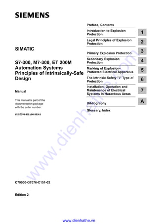
- 1. Preface, Contents Introduction to Explosion Protection 1 Legal Principles of Explosion Protection 2 Primary Explosion Protection 3 Secondary Explosion Protection 4 Marking of Explosion- Protected Electrical Apparatus 5 The Intrinsic Safety ”i” Type of Protection 6 Installation, Operation and Maintenance of Electrical Systems in Hazardous Areas 7 Bibliography A Glossary, Index C79000-G7076-C151-02 Edition 2 S7-300, M7-300, ET 200M Automation Systems Principles of Intrinsically-Safe Design Manual This manual is part of the documentation package with the order number: 6ES7398-8RA00-8BA0 SIMATIC www.dienhathe.vn www.dienhathe.com
- 2. Principlesof Intrinsically-Safe Design This manual contains notices which you should observe to ensure your own personal safety, as well as to protect the product and connected equipment. These notices are highlighted in the manual by a warning triangle and are marked as follows according to the level of danger: ! Danger indicatesthatdeath,severepersonalinjuryorsubstantialpropertydamagewillresultifproperprecautionsare nottaken. ! Warning indicatesthatdeath,severepersonalinjuryorsubstantialpropertydamagecanresultifproperprecautionsare nottaken. ! Caution indicates that minor personal injury or property damage can result if proper precautions are not taken. Note drawsyourattentiontoparticularlyimportantinformationontheproduct,handlingtheproduct,ortoaparticular partof the documentation. The device/system may only be set up and operated in conjunction with this manual. Only qualified personnel should be allowed to install and work on this equipment. Qualified persons are defined as persons who are authorized to commission, to ground, and to tag circuits, equipment, and sys- tems in accordance with established safety practices and standards. Note the following: ! Warning Thisdeviceanditscomponentsmayonlybeusedfortheapplicationsdescribedinthecatalogorthetechnical description,and only in connection with devices or components from other manufacturers which have been approved or recommended by Siemens. Thisproductcanonlyfunctioncorrectlyandsafelyifitistransported,stored,setup,andinstalledcorrectly,and operatedand maintained as recommended. SIMATICR, SIMATIC NETR and SIMATIC HMIR are registered trademarks of SIEMENS AG. Third parties using for their own purposes any other names in this document which refer to trademarksmight infringe upon the rights of the trademark owners. We have checked the contents of this manual for agreement with the hardwareandsoftwaredescribed.Sincedeviationscannotbeprecluded entirely, we cannot guarantee full agreement. However, the data in this manualarereviewedregularlyandanynecessarycorrectionsincludedin subsequenteditions. Suggestions for improvement are welcomed. E Siemens AG 1997 Subject to change without prior notice. Disclaimer of LiabilityCopyright E SiemensAG 1997 All rights reserved The reproduction, transmission or use of this document or its contents is notpermittedwithoutexpresswrittenauthority.Offenderswillbeliablefor damages.Allrights,includingrightscreatedbypatentgrantorregistration of a utility model or design, are reserved. Siemens AG BereichAutomatisierungs-undAntriebstechnik GeschaeftsgebietIndustrie-Automatisierungssysteme Postfach 4848, D- 90327 Nuernberg Siemens Aktiengesellschaft C79000-G7076-C151 Safety Guidelines Qualified Personnel Correct Usage Trademarks www.dienhathe.vn www.dienhathe.com
- 3. iii Principles of Intrinsically-Safe Design C79000-G7076-C151-02 Preface This manual provides you with information which you must take into account, when S Planning, S Installing, and S Commissioning electrical systems in hazardous areas. The manual “S7-300, M7-300, ET 200 M Automation Systems Principles of Intrinsically-Safe Design” contains basic information on explosion protection and the use of intrinsically-safe modules. The manual is subdivided into the following topics: Legal principles of explosion protection Primary explosion protection Secondary explosion protection The intrinsic safety ”i” type of protection Installation, operation and maintenance of electrical systems in hazardous areas Sect. 2 Sect. 3 Sect. 4 Sect. 6 Sect. 7 Introduction to explosion protection Sect. 1 Marking of explosion-protected electrical apparatus Sect. 5 Purpose of this manual Contents of the manual www.dienhathe.vn www.dienhathe.com
- 4. iv Principlesof Intrinsically-Safe Design C79000-G7076-C151-02 Technical descriptions of the individual blocks are provided in the reference manual “S7-300, M7-300, ET 200 M Automation Systems I/O Modules with Intrinsically-Safe Signals”, which is included in the same documentation package. This reference manual is sub-divided into the following topics: Mechanical configuration of an automation system with SIMATIC S7 explosion-proof constructional hardware SIMATIC S7 Ex digital modules SIMATIC S7 Ex analog modules SIMATIC S7 HART analog modules The minimum igntion curves depicted in this manual are subject to graphical inaccuracies. Always use the minimum ignition curves from the valid stan- dard or the relevant PTB reports for concrete calculations. The manual contains the following orientation aids in order to help you access special infomation: S At the beginning of the manual there is a complete overall table of contents as well as a list of the figures and tables contained in the complete manual. S The individual chapters have a column in the left-hand margin which summarizes the contents of the respective section. S After the Appendixes there is a glossary in which important technical terms used in the manual are defined. S At the end of the manual there is a detailed index which enables you to find the desired information quickly. Should you have any further questions on using the products described which are not answered in the manual, please contact the Siemens representative in your area. If you have any questions or remarks on the manual itself, please fill out the questionnaire at the end of the manual and send it to the address shown on the form. Please also enter your personal evaluation of the manual in the questionnaire. Siemens also offers a number of training courses to introduce you to the SIMATIC S7 automation system. Please contact your regional training center or the central training center in Nuremberg, Germany for details: D-90327 Nurernberg, Tel. (+49) (911) 895 3154. You can obtain up-to-date information on SIMATIC products from: S the Internet under http://www.ad.siemens.de/ S the Fax-Polling number 08765 - 93 00 - 50 00 Not in this Manual Note Accessing Information in the Manual Further Support Preface www.dienhathe.vn www.dienhathe.com
- 5. v Principles of Intrinsically-Safe Design C79000-G7076-C151-02 Contents Preface iii. . . . . . . . . . . . . . . . . . . . . . . . . . . . . . . . . . . . . . . . . . . . . . . . . . . . . . . . . . . . . . . . 1 Introduction to Explosion Protection 1-1. . . . . . . . . . . . . . . . . . . . . . . . . . . . . . . . . . . . 1.1 Explanation of Terms 1-2. . . . . . . . . . . . . . . . . . . . . . . . . . . . . . . . . . . . . . . . . . . . 1.2 Explosive Atmosphere 1-3. . . . . . . . . . . . . . . . . . . . . . . . . . . . . . . . . . . . . . . . . . . 1.2.1 Concentration of the Flammable Substances 1-3. . . . . . . . . . . . . . . . . . . . . . . . 1.2.2 Existence of a Hazardous Amount 1-5. . . . . . . . . . . . . . . . . . . . . . . . . . . . . . . . . 1.2.3 Effectiveness of the Ignition Source 1-6. . . . . . . . . . . . . . . . . . . . . . . . . . . . . . . . 1.3 Protective Measures 1-7. . . . . . . . . . . . . . . . . . . . . . . . . . . . . . . . . . . . . . . . . . . . . 2 Legal Principles of Explosion Protection 2-1. . . . . . . . . . . . . . . . . . . . . . . . . . . . . . . . . 2.1 Development Within the Federal Republic of Germany 2-2. . . . . . . . . . . . . . . 2.2 General Legal Requirements According to Articles 24 and 25 of the German Factory Act 2-3. . . . . . . . . . . . . . . . . . . . . . . . . . . . . . . . . . . . . 2.3 Regulations for Electrical Apparatus in Hazardous Areas (ElexV) 2-5. . . . . . 2.4 Regulations for Equipment for the Storage, Filling and Conveying of Flammable Liquids on Land (VbF) 2-9. . . . . . . . . . . . . . . . . . . . . . . . . . . . . . . 2.5 Explosion-Protection Guidelines (EX-RL) of the Employers’ Liability Insurance Association for the Chemical Industry 2-10. . . . . . . . . . . . . . . . . . . . . 2.6 Overview of Specifications, Standards and Regulations 2-12. . . . . . . . . . . . . . . 2.7 National Authorized Testing Stations 2-16. . . . . . . . . . . . . . . . . . . . . . . . . . . . . . . 2.8 Testing Stations Within the EU 2-18. . . . . . . . . . . . . . . . . . . . . . . . . . . . . . . . . . . . 2.9 Testing Stations Outside the EC 2-20. . . . . . . . . . . . . . . . . . . . . . . . . . . . . . . . . . . 2.10 Standardization Commissions 2-21. . . . . . . . . . . . . . . . . . . . . . . . . . . . . . . . . . . . . 2.11 International Publication of European Standards for Explosion Protection 2-24. . . . . . . . . . . . . . . . . . . . . . . . . . . . . . . . . . . . . . . . . . . . . . . . . . . . . . 2.12 Test and Certification Procedures 2-25. . . . . . . . . . . . . . . . . . . . . . . . . . . . . . . . . . 3 Primary Explosion Protection 3-1. . . . . . . . . . . . . . . . . . . . . . . . . . . . . . . . . . . . . . . . . . . 3.1 Avoiding Flammable Liquids 3-2. . . . . . . . . . . . . . . . . . . . . . . . . . . . . . . . . . . . . . 3.2 Increasing the Flash Point 3-2. . . . . . . . . . . . . . . . . . . . . . . . . . . . . . . . . . . . . . . . 3.3 Limiting the Concentration 3-2. . . . . . . . . . . . . . . . . . . . . . . . . . . . . . . . . . . . . . . . 3.4 Inertness 3-3. . . . . . . . . . . . . . . . . . . . . . . . . . . . . . . . . . . . . . . . . . . . . . . . . . . . . . . 3.5 Ventilation 3-3. . . . . . . . . . . . . . . . . . . . . . . . . . . . . . . . . . . . . . . . . . . . . . . . . . . . . . 3.6 Design-Related Measures 3-4. . . . . . . . . . . . . . . . . . . . . . . . . . . . . . . . . . . . . . . . www.dienhathe.vn www.dienhathe.com
- 6. vi Principles of Intrinsically-Safe Design C79000-G7076-C151-02 4 Secondary Explosion Protection 4-1. . . . . . . . . . . . . . . . . . . . . . . . . . . . . . . . . . . . . . . . . 4.1 Zone Classification 4-2. . . . . . . . . . . . . . . . . . . . . . . . . . . . . . . . . . . . . . . . . . . . . . 4.1.1 Assessing the Explosion Hazards in Zones 10 and 11 4-3. . . . . . . . . . . . . . . . 4.1.2 Notes on zone classification for Zone 0 and Zone 1 4-5. . . . . . . . . . . . . . . . . . 4.2 Types of Protection 4-6. . . . . . . . . . . . . . . . . . . . . . . . . . . . . . . . . . . . . . . . . . . . . . 4.2.1 General Stipulations (DIN EN 50014 / VDE 0170/171, Part 1) 4-6. . . . . . . . . 4.2.2 Oil Immersion ”o”(DIN EN 50015 / VDE 0170/0171, Part 2) 4-6. . . . . . . . . . . 4.2.3 Pressurized Enclosure ”p” (DIN EN 50016 / VDE 0170/0171, Part 3) 4-7. . . 4.2.4 Sand Filling ”q”(DIN EN 50017 / VDE 0170/0171 Part 4) 4-8. . . . . . . . . . . . . . 4.2.5 Flameproof Enclosure ”d”(DIN EN 50018 / VDE 0170/0171 Part 5) 4-9. . . . . 4.2.6 Increased Safety ”e”(DIN EN 50019 / VDE 070/0171 Part 6) 4-10. . . . . . . . . . 4.2.7 Intrinsic Safety ”i”(DIN EN 50020 / VDE 0170/0171 Part 7) 4-12. . . . . . . . . . . . 4.2.8 Encapsulation ”m” (DIN EN 50028 / VDE 0170/0171 Part 9) 4-16. . . . . . . . . . . 4.2.9 Intrinsically Safe Electrical Systems ”i”(DIN EN 50039 / VDE 0170/0171 Part 10) 4-17. . . . . . . . . . . . . . . . . . . . . . . . 4.3 Safety Characteristics 4-19. . . . . . . . . . . . . . . . . . . . . . . . . . . . . . . . . . . . . . . . . . . . 4.3.1 Explosion Groups 4-21. . . . . . . . . . . . . . . . . . . . . . . . . . . . . . . . . . . . . . . . . . . . . . . 4.3.2 Temperature Classes 4-24. . . . . . . . . . . . . . . . . . . . . . . . . . . . . . . . . . . . . . . . . . . . 4.4 Regulations for Explosion Protection Outside the CENELEC Member States 4-26. . . . . . . . . . . . . . . . . . . . . . . . . . . . . . . . . . . . . . . . . . . . . . . . . 5 Marking of Explosion-Protected Electrical Equipment 5-1. . . . . . . . . . . . . . . . . . . . . 5.1 Type and Method of Marking 5-2. . . . . . . . . . . . . . . . . . . . . . . . . . . . . . . . . . . . . . 5.2 Comparison Between Old and New Markings 5-6. . . . . . . . . . . . . . . . . . . . . . . 5.3 Examples of Marking 5-8. . . . . . . . . . . . . . . . . . . . . . . . . . . . . . . . . . . . . . . . . . . . 6 The Intrinsic Safety ”i” Type of Protection 6-1. . . . . . . . . . . . . . . . . . . . . . . . . . . . . . . . 6.1 Principles of Intrinsic Safety 6-2. . . . . . . . . . . . . . . . . . . . . . . . . . . . . . . . . . . . . . 6.1.1 Functional Principle 6-2. . . . . . . . . . . . . . . . . . . . . . . . . . . . . . . . . . . . . . . . . . . . . . 6.1.2 Minimum Ignition Curves for a Resistive Circuit 6-6. . . . . . . . . . . . . . . . . . . . . . 6.1.3 Minimum Ignition Curves for a Capacitive Circuit 6-8. . . . . . . . . . . . . . . . . . . . . 6.1.4 Minimum Ignition Curves for an Inductive Circuit 6-10. . . . . . . . . . . . . . . . . . . . . 6.1.5 Using the Minimum Ignition Curves 6-11. . . . . . . . . . . . . . . . . . . . . . . . . . . . . . . . 6.2 Apparatus in an Intrinsically Safe Circuit 6-12. . . . . . . . . . . . . . . . . . . . . . . . . . . . 6.2.1 Classification of Intrinsically Safe Apparatus 6-12. . . . . . . . . . . . . . . . . . . . . . . . 6.2.2 Principle of Operation of Safety Barriers 6-16. . . . . . . . . . . . . . . . . . . . . . . . . . . . 6.2.3 Apparatus without Metallic Isolation 6-17. . . . . . . . . . . . . . . . . . . . . . . . . . . . . . . . 6.2.4 Apparatus with Metallic Isolation 6-19. . . . . . . . . . . . . . . . . . . . . . . . . . . . . . . . . . . 6.3 Interconnection in the Intrinsically Safe Circuit 6-21. . . . . . . . . . . . . . . . . . . . . . . 6.3.1 Intrinsically-Safe Circuit with One Item of Associated Electrical Apparatus 6-21. . . . . . . . . . . . . . . . . . . . . . . . . . . . . . . . . . . . . . . . . . . . . 6.3.2 Intrinsically-Safe Circuit with Two or More Items of Associated Electrical Apparatus (Requirements for Installation in Zones 0 and 1) 6-23. . . Contents www.dienhathe.vn www.dienhathe.com
- 7. vii Principles of Intrinsically-Safe Design C79000-G7076-C151-02 7 Installation, Operation and Maintenance of Electrical Systems in Hazardous Areas 7-1. . . . . . . . . . . . . . . . . . . . . . . . . . . . . . . . . . . . . . . . . . . . . . . . . . . . . . . 7.1 Installation Specifications 7-2. . . . . . . . . . . . . . . . . . . . . . . . . . . . . . . . . . . . . . . . . 7.2 Contact Protection and Equipotential Bonding 7-5. . . . . . . . . . . . . . . . . . . . . . . 7.3 Cables and Conductors 7-7. . . . . . . . . . . . . . . . . . . . . . . . . . . . . . . . . . . . . . . . . . 7.4 Installation in Zone 0 7-8. . . . . . . . . . . . . . . . . . . . . . . . . . . . . . . . . . . . . . . . . . . . . 7.5 Installation in Zone 1 7-9. . . . . . . . . . . . . . . . . . . . . . . . . . . . . . . . . . . . . . . . . . . . . 7.6 Installation in Zone 2 7-11. . . . . . . . . . . . . . . . . . . . . . . . . . . . . . . . . . . . . . . . . . . . 7.7 Installation in Zones 10 and 11 7-12. . . . . . . . . . . . . . . . . . . . . . . . . . . . . . . . . . . . 7.8 Operation, Maintenance, Faults and Repairs 7-14. . . . . . . . . . . . . . . . . . . . . . . . 7.9 Systematic Procedure for the Installation of an Explosion-Proof System by Means of an Example 7-18. . . . . . . . . . . . . . . . . . . . . . . . . . . . . . . . . . . . . . . . . A Bibliography A-1. . . . . . . . . . . . . . . . . . . . . . . . . . . . . . . . . . . . . . . . . . . . . . . . . . . . . . . . . . . Glossary Glossary-1. . . . . . . . . . . . . . . . . . . . . . . . . . . . . . . . . . . . . . . . . . . . . . . . . . . . . . . Index Index-1. . . . . . . . . . . . . . . . . . . . . . . . . . . . . . . . . . . . . . . . . . . . . . . . . . . . . . . . . . Contents www.dienhathe.vn www.dienhathe.com
- 8. viii Principles of Intrinsically-Safe Design C79000-G7076-C151-02 Figures 1-1 Concentration of a flammable subtance in the air (explosion limits depend on the material) 1-4. . . . . . . . . . . . . . . . . . . . . . . . . . . 2-1 Standardized Ex sign 2-7. . . . . . . . . . . . . . . . . . . . . . . . . . . . . . . . . . . . . . . . . . . . 2-2 Interaction of the legal principles of explosion protection in the Federal Republic of Germany 2-13. . . . . . . . . . . . . . . . . . . . . . . . . . . . . . . . . . . . . 2-3 Transitional regulations for Elex in the five new German states /1/ 2-17. . . . . 2-4 Interaction of the standardization committees 2-23. . . . . . . . . . . . . . . . . . . . . . . 4-1 Example of a zone division for tank ventilation 4-5. . . . . . . . . . . . . . . . . . . . . 4-2 Type of protection oil immersion ”o” (oil-immersion) 4-6. . . . . . . . . . . . . . . . . . 4-3 Pressurized enclosure ”p” (pressurization) 4-7. . . . . . . . . . . . . . . . . . . . . . . . . . 4-4 Sand filling ”q” 4-8. . . . . . . . . . . . . . . . . . . . . . . . . . . . . . . . . . . . . . . . . . . . . . . . . 4-5 Flameproof enclosure ”d” 4-9. . . . . . . . . . . . . . . . . . . . . . . . . . . . . . . . . . . . . . . . . 4-6 Cable entry into flameproof enclosures 4-10. . . . . . . . . . . . . . . . . . . . . . . . . . . . . 4-7 Increased safety ”e” 4-11. . . . . . . . . . . . . . . . . . . . . . . . . . . . . . . . . . . . . . . . . . . . . 4-8 Cable entries for devices with ”Increased safety” 4-12. . . . . . . . . . . . . . . . . . . . 4-9 Intrinsic safety ”i” 4-13. . . . . . . . . . . . . . . . . . . . . . . . . . . . . . . . . . . . . . . . . . . . . . 4-10 Intrinsically safe circuit (example) 4-14. . . . . . . . . . . . . . . . . . . . . . . . . . . . . . . . . . 4-11 Encapsulation ”m” 4-16. . . . . . . . . . . . . . . . . . . . . . . . . . . . . . . . . . . . . . . . . . . . . . . 4-12 Intrinsically safe systems ”i-SYST” 4-18. . . . . . . . . . . . . . . . . . . . . . . . . . . . . . 5-1 Standardized EX sign 5-2. . . . . . . . . . . . . . . . . . . . . . . . . . . . . . . . . . . . . . . . . . . . 5-2 Marking of a SIEMENS analog output module for connecting actuators in a hazardous area 5-3. . . . . . . . . . . . . . . . . . . . . . . . . . . . . . . . . . . . . 5-3 Example of a certificate number 5-4. . . . . . . . . . . . . . . . . . . . . . . . . . . . . . . . . . . 5-4 Example for the marking of explosion-protected electrical equipment 5-5. . . 6-1 Block diagram for voltage/current limitation in the ”i” intrinsic safety type of protection 6-3. . . . . . . . . . . . . . . . . . . . . . . . . . . . . . . . . . . . . . . . . . 6-2 Output characteristic curve for resistive and electronic current limiting 6-4. . 6-3 Minimum ignition curves for resistive circuits of Explosion Groups I, IIA, IIC (DIN EN 50020 of 05.78, Appendix A) 6-7. . . . . . . . . . . . . . . . . . . . . 6-4 Minimum ignition voltages in capacitive circuits (DIN EN 50020, Appendix A) 6-9. . . . . . . . . . . . . . . . . . . . . . . . . . . . . . . . . . . . . . 6-5 Minimum ignition curves for inductive circuits to DIN EN 50020, Appendix A 6-11. . . . . . . . . . . . . . . . . . . . . . . . . . . . . . . . . . . . . . . . . . . . . . . . . . . . . 6-6 Typical structure of an intrinsically-safe measuring and control system 6-12. . 6-7 Classification of intrinsically-safe apparatus 6-13. . . . . . . . . . . . . . . . . . . . . . . . 6-8 Flow chart for selecting electrical apparatus for Zone 1 6-15. . . . . . . . . . . . . . . 6-9 Block diagram of a safety barrier 6-16. . . . . . . . . . . . . . . . . . . . . . . . . . . . . . . . . . 6-10 Way of working of the equipotential bonding connection 6-18. . . . . . . . . . . . . . 6-11 Application with metallic isolation 6-19. . . . . . . . . . . . . . . . . . . . . . . . . . . . . . . . . . 6-12 Permissible interconnection within an intrinsically-safe circuit 6-22. . . . . . . . . . Contents www.dienhathe.vn www.dienhathe.com
- 9. ix Principles of Intrinsically-Safe Design C79000-G7076-C151-02 6-13 Parallel connection of two outputs (only current addition possible) 6-26. . . . . . 6-14 Series connection of two outputs (only voltage addition possible) 6-27. . . . . . 6-15 State in which series and parallel connections are possible in case of faults 6-28. . . . . . . . . . . . . . . . . . . . . . . . . . . . . . . . . . . . . . . . . . . . . . . . . 6-16 Series connection 1 6-30. . . . . . . . . . . . . . . . . . . . . . . . . . . . . . . . . . . . . . . . . . . . . . 6-17 Series connection 2 6-30. . . . . . . . . . . . . . . . . . . . . . . . . . . . . . . . . . . . . . . . . . . . . . 6-18 Parallel connection 1 6-31. . . . . . . . . . . . . . . . . . . . . . . . . . . . . . . . . . . . . . . . . . . . 6-19 Parallel connection 2 6-31. . . . . . . . . . . . . . . . . . . . . . . . . . . . . . . . . . . . . . . . . . . . . 6-20 Series or parallel connection 6-32. . . . . . . . . . . . . . . . . . . . . . . . . . . . . . . . . . . . . . 6-21 Minimum ignition curve diagram for connection with electronic current limiting equipment (safety factor of 1.5 included) 6-33. . . . . . . . . . . . . . . . . . . . . 6-22 Example for the connection of hree associated apparatus with an intrinsically-safe apparatus 6-35. . . . . . . . . . . . . . . . . . . . . . . . . . . . . . . . . . . . . . . 6-23 Cumulative output lines of the connection realized in Figure 6-19 6-35. . . . . . 6-24 Minimum ignition curve diagram for connection with electronic current limiting equipment (safety factor 1.5 included) 6-36. . . . . . . . . . . . . . . . 7-1 Equipotential bonding in a hazardous area 7-6. . . . . . . . . . . . . . . . . . . . . . . . . . Contents www.dienhathe.vn www.dienhathe.com
- 10. x Principles of Intrinsically-Safe Design C79000-G7076-C151-02 Tables 2-1 Responsibility in planning and installing electrical systems in hazardous areas 2-8. . . . . . . . . . . . . . . . . . . . . . . . . . . . . . . . . . . . . . . . . . . . . . 2-2 Example: Collection of examples explosion protection guideline ZH 1/10 2-11. . . . . . . . . . . . . . . . . . . . . . . . . . . . . . . . . . . . . . . . . . . . . . . 2-3 Summary of the standards and regulations of the Federal Republic of Germany (status: 6/95) 2-14. . . . . . . . . . . . . . . . . . . . . . . . . . . . . . . . . . . . . . . . 2-4 Admitted testing stations of the CE 2-19. . . . . . . . . . . . . . . . . . . . . . . . . . . . . . . . 2-5 Summary of publications for the explosion protected electrical apparatus 2-21. . . . . . . . . . . . . . . . . . . . . . . . . . . . . . . . . . . . . . . . . . . . . . 2-6 Designation of European Standards concerning explosion protection 2-24. . . 4-1 Zones for flammable gases, vapors and mist /1/ 4-2. . . . . . . . . . . . . . . . . . . . . 4-2 Zones for flammable dusts /1/ 4-3. . . . . . . . . . . . . . . . . . . . . . . . . . . . . . . . . . . . . 4-3 Combustion and explosion characteristics in dust1) 4-3. . . . . . . . . . . . . . . . . . 4-4 Zones for rooms used for medical purposes /1/ 4-4. . . . . . . . . . . . . . . . . . . . . . 4-5 Safety characteristics of selected flammable gases 4-20. . . . . . . . . . . . . . . . . . 4-6 Explosion Group I 4-21. . . . . . . . . . . . . . . . . . . . . . . . . . . . . . . . . . . . . . . . . . . . . . . 4-7 Explosion group II 4-21. . . . . . . . . . . . . . . . . . . . . . . . . . . . . . . . . . . . . . . . . . . . . . . 4-8 Safety characteristics of flammable gases and vapors1) 4-22. . . . . . . . . . . . . . 4-9 Percentage distribution of the materials amongst the temperature classes and material groups 4-24. . . . . . . . . . . . . . . . . . . . . . . . . . . . . . . . . . . . . . 4-10 Temperature classes 4-25. . . . . . . . . . . . . . . . . . . . . . . . . . . . . . . . . . . . . . . . . . . . . 4-11 Overview of the ”i” intrinsic type of protection outside the CENELEC states 4-27. . . . . . . . . . . . . . . . . . . . . . . . . . . . . . . . . . . . . . . . . . . . 5-1 Meaning of suffix letter for certificates 5-4. . . . . . . . . . . . . . . . . . . . . . . . . . . 5-2 Markings of electrical equipment according to the old and new standards 5-6. . . . . . . . . . . . . . . . . . . . . . . . . . . . . . . . . . . . . . . . . . . . . . . . . . 5-3 Examples of the marking for explosion-protected electrical equipment 5-8. . . . . . . . . . . . . . . . . . . . . . . . . . . . . . . . . . . . . . . . . . . . . 6-1 Comparison of the safety-relevant limits 6-21. . . . . . . . . . . . . . . . . . . . . . . . . . . . 7-1 Installation specifications 7-2. . . . . . . . . . . . . . . . . . . . . . . . . . . . . . . . . . . . . . . . . 7-2 Information for work to be carried out on explosion-protected apparatus 7-15 Contents www.dienhathe.vn www.dienhathe.com
- 11. 1-1 Principles of Intrinsically-Safe Design C79000-G7076-C151-02 Introduction to Explosion Protection The following sections explain the most important basic terms in explosion protection, physical interdependences and protective measures. Section Description Page 1.1 Explanation of Terms 1-2 1.2 Explosive Atmosphere 1-3 1.3 ProtectiveMeasures 1-7 Contents Chapter Overview 1 www.dienhathe.vn www.dienhathe.com
- 12. 1-2 Principles of Intrinsically-Safe Design C79000-G7076-C151-02 1.1 Explanation of Terms The following section explains the main terms used in this documentation. The official defintion of these terms can be found in ElexV /1/ (Regulations for electrical systems in hazardous areas). Within the scope of explosion protection, industrial premises in which the assesment of explosion hazard is made, are considered on the basis of S The physical and chemical principles of explosion protection; S The safety characteristics of an explosive atmosphere; S The operational and local circumstances. In the VDE regulations industrial premises are considered to be an outdoor location or a room serving for any business operations and regularly accessible to untrained persons. ”Outdoor locations” or the word ”room” is intended to mean a generally limited volume which, in turn, can be subdivided into zones (See Section 4.1) subject to different levels of danger with respect to explosion protection. The word area is used in the following sections as a synonym for industrial premises, in accordance with international and other German regulations. This term covers explosions which, by defintion, cause an exothermic reaction (i.e. with heat emission) in explosive mixtures or explosive atmospheres; this reaction takes place on account of the temperature rise caused by the released heat, with a high velocity (order of magnitude m/s) and sudden pressure and report. In contrast, there is a deflagration if the propagation rate of the reaction is in the cm/s range. If the reaction takes place with an extremely high pressure and report and with a velocity of some km/s it is known as a detonation. This is an area in which there may be a risk of explosion or dangerous, explosive atmosphere on account of the local and operational circumstances. This is understood to mean all the system sections serving entirely or partly for the application of electrical power. It includes system sections for generating, conducting, distributing, storing, measuring, regulating, converting/ transforming and consuming electrical power. Electrical systems are formed by interconnecting electrical equipment units. Overview Area Explosion Hazardous area Electrical equipment Introduction to Explosion Protection www.dienhathe.vn www.dienhathe.com
- 13. 1-3 Principlesof Intrinsically-Safe Design C79000-G7076-C151-02 1.2 Explosive Atmosphere An explosive atmosphere is a mixture of air and flammable gases, vapors, mist or dusts which can ignite in a suitable concentration under atmospheric conditions, and in which a combustion is self-propagating after ignition from the ignition source. The atmospheric conditions applying are a total pressure of 0.8 bars to 1.1 bars and mixture temperatures of –20°C to +60°C. The following aspects must be considered when judging its explosivity or its ignition: S Degree of dispersion of the flammable substances S Concentration of the flammable substances S Existence of a hazardous quantity S Effectiveness of the ignition source. 1.2.1 Concentration of the Flammable Substances Parts of a liquid turn into the gaseous aggregate state on account of evaporation. For this reason, a mixture of vapors and air develops above an open liquid surface; the mixture need not necessarily be flammable. If the temperature is sufficiently high, however, the liquid develops such large amounts of vapor by evaporation that together with the air these form a flammable mixture above the liquid. This temperature is known as the flash point and is determined in a closed cup under specified conditions by means of extraneous ignition. However, continuous combustion is not yet possible because insufficient vapors continue to develop at this liquid temperature. If the temperature is higher and just sufficient for the changed vapor/air mixture to continue burning above the liquid, the temperature is known as the combustion point. The values of the flash point and combustion point are not physical constants but so-called substance-related characteristics of the gas-air mixtures. These are defined as safety characteristics (see also Section 4.3) because other factors such as convection and diffusion also contribute to the determination of the above temperatures. The flash point can be affected by admixtures to flammable liquids. Definition Overview Liquids - gases/vapors Flash point Introduction to Explosion Protection www.dienhathe.vn www.dienhathe.com
- 14. 1-4 Principlesof Intrinsically-Safe Design C79000-G7076-C151-02 The development of an explosive atmosphere depends on the mixture concentration forming over the liquid. When there is a mixture concentration with which the mixture is just barely explosive, the lower explosion limit (also known as the lower ignition limit) has been reached; the corresponding temperature is known as the lower explosion point. If the mixture concentration is increased, the degree of concentration finally reached is such that the mixture contains insufficient oxygen on account of the higher content of gases and vapors, and is therefore no longer explosive; the upper explosion limit or ignition limit has been reached. Above this limit, the mixture is too rich but is still combustible in an oxidizing agent. The region of concentration between the explosion limits (ignition limits) is known as the explosion region (ignition range); see Figure 1-1. ÇÇÇÇÇ ÇÇÇÇÇ ÇÇÇÇÇÇÇÇÇÇ ÇÇÇÇÇ ÇÇÇÇÇ ÇÇÇÇÇÇÇÇÇÇ ÇÇÇÇÇ ÊÊÊÊÊÊÊÊÊÊÊÊÊ ÊÊÊÊÊÊÊÊÊÊÊÊÊ ÊÊÊÊÊÊÊÊÊÊÊÊÊÊÊÊÊÊÊÊÊÊÊÊÊÊ ÊÊÊÊÊÊÊÊÊÊÊÊÊ ÊÊÊÊÊÊÊÊÊÊÊÊÊ ÊÊÊÊÊÊÊÊÊÊÊÊÊÊÊÊÊÊÊÊÊÊÊÊÊÊ ÊÊÊÊÊÊÊÊÊÊÊÊÊ ÉÉÉÉ ÉÉÉÉ ÉÉÉÉÉÉÉÉ ÉÉÉÉ ÉÉÉÉ ÉÉÉÉÉÉÉÉ ÉÉÉÉ Explosion region Concentration of air Mixture too rich 0 % 100 % Mixture too lean 0 %100 % Lowerexplosionlimit Upperexplosionlimit Concentration of the combustible material Fig. 1-1 Concentration of a flammable subtance in the air (explosion limits depend on the material) For a mixture with oxygen, the upper explosion limit is considerably higher than for a mixture with air. If an inert gas is substituted for oxygen or air, an explosion is no longer possible. The ignition temperature of a flammable gas or liquid is the lowest temperature determined in a test device for a heated wall on which the flammable substance mixed with air just barely ignites (see also Table 4-5). The ignition temperatures of gases can be classified in various temperature classes (see Section 4.3.2). Lower explosion limit Upper explosion limit Explosion region Introduction to Explosion Protection www.dienhathe.vn www.dienhathe.com
- 15. 1-5 Principlesof Intrinsically-Safe Design C79000-G7076-C151-02 Solid substances often occur in a comminuted form, such as dust. Dust deposits can be compared to a porous body and have a voidage of up to 90 %. When dust of a small grain size are whirled, it can ignite more easily because the surface increases as the comminution increases. When the temperature of a dust deposit is increased, spontaneous ignition of the combustible substance in the form of dust occurs. A smoldering or glowing fire occurs which always starts at temperatures lower than the explosion of the same dust as a dust/air mixture. Such a smoldering fire, particularly with whirling of the dust particles, can serve as the ignition source for a dust/air mixture. For this reason, the smoldering temperature, determined for the ignition of a 5-mm-high dust layer, is an important safety characteristic for dusts. If the layer thicknesses increase, smoldering can occur below this smoldering temperature. Dust/air mixtures also have explosion limits and ranges, similarly to the gases and vapors. Table 4-3 summarizes safety characteristics for dust of the most common materials. Note Unstable substances and gases: With certain chemically unstable substances and gases such as acetylene, an exothermic reaction can be initiated by ignition, even when no oxygen or air is present. 1.2.2 Existence of a Hazardous Amount An explosive atmosphere in a hazardous amount is a dangerous explosive atmosphere, i.e. the quantity is such that direct or indirect injury or damage can be expected in the event of an explosion. As a rule, 10 litres of cohesive explosive atmosphere in a closed room can be considered as hazardous, irrespective of the room’s size. However, even lesser amounts can furthermore be considered dangerous, especially if they are in the vicinity of persons and are ignited there. A rule of thumb: Room volume v 10,000 x mixture volume Example: This is reached with only 8 litres in a room of 80 m3 volume. Dust Smoldering or glowing fire Smoldering temperature Introduction to Explosion Protection www.dienhathe.vn www.dienhathe.com
- 16. 1-6 Principlesof Intrinsically-Safe Design C79000-G7076-C151-02 1.2.3 Effectiveness of the Ignition Source The effectiveness of an ignition source and therefore its ability to ignite an explosive atmosphere depends on the energy of the ignition source and the properties of the explosive atmosphere. According to /1/ (from the explosion protection guidelines), the following are ignition sources: S Hot surfaces S Flames and hot gases S Mechanically produced sparks S Electrical equipment S Transient currents, cathodic protection S Static electricity S Lightning strikes S Electromagnetic waves S Optical radiation S Ionizing radiation S Ultrasound S Adiabatic compression, shock waves of flowing gases S Chemical reactions. In practice, electrical devices and systems form the major part of the possible ignition sources. Switching sparks and components overheated by excessively high currents (i.e. in the event of a short-circuit fault) can act as an ignition source. Definition Introduction to Explosion Protection www.dienhathe.vn www.dienhathe.com
- 17. 1-7 Principlesof Intrinsically-Safe Design C79000-G7076-C151-02 1.3 Protective Measures There are two basic measures for avoiding explosions: 1. Preventing the formation of a dangerous, explosive atmosphere, called primary explosion protection 2. Preventing the ignition of a dangerous, explosive atmosphere, called secondary explosion protection Note According to ElexV, Paragraph 7, measures for preventing an explosive atmosphere are mandatory. Primary explosion protection is understood to mean all measures which prevent or restrict the development of a dangerous explosive atmosphere (see Chapter 3). This can, for example, be achieved by: S Avoiding the use of flammable liquids; S Inerting; S Substituting non-combustible substances for combustible substances; S Limiting the concentration below the lower and above the upper explo- sion limit; S Suitable equipment design; S Natural and technical ventilation measures. Detailed considerations on primary explosion protection can be found in Part E 1 ”Measures which prevent or restrict the formation of a dangerous explosive atmosphere” (in German) of the Ex-RL /1/, /4/ (see also Chapter 3). Avoiding explosions Primary explosion protection Introduction to Explosion Protection www.dienhathe.vn www.dienhathe.com
- 18. 1-8 Principlesof Intrinsically-Safe Design C79000-G7076-C151-02 There are, however, many applications in which primary protective measures cannot be applied. Secondary explosion protection measures prevent ignition, thus ensuring the safety of personnel and equipment in hazardous areas. Secondary explosion protection encompasses all measures which prevent the ignition of an explosive atmosphere. There are different standardized types of protection which are described in Section 4.2. With regard to electrical equipment secondary explosion protection is concerned with the observance of constructional requirements for electrical equipment with explosion protection. These are intended to prevent an explosion or, in the event of an explosion in the interior of the equipment, to prevent ignition of the ambient explosive atmosphere (see also Chapter 4) by means of design and/or circuiting measures. Secondary explosion protection Introduction to Explosion Protection www.dienhathe.vn www.dienhathe.com
- 19. 2-1 Principles of Intrinsically-Safe Design C79000-G7076-C151-02 Legal Principles of Explosion Protection This section informs on the legal principles of explosion protection. Section Description Page 2.1 Development Within the Federal Republic of Germany 2-2 2.2 General Legal Requirements According to Articles 24 and 25 of the German Factory Act 2-3 2.3 Regulations for Electrical Apparatus in Hazardous Areas (ElexV) 2-5 2.4 Regulations for Equipment for the Storage, Filling and Conveying of Flammable Liquids on Land (VbF) 2-9 2.5 Explosion-Protection Guidelines (EX-RL) of the Employers’ Liability Insurance Association for the Chemical Industry 2-10 2.6 Overview of Specifications, Standards and Regulations 2-12 2.7 National Authorized TestingStations 2-16 2.8 Testing Stations Within the EU 2-18 2.9 Testing Stations Outside the EC 2-20 2.10 StandardizationCommissions 2-21 2.11 International Publication of European Standards for Explosion Protection 2-24 2.12 Test and Certification Procedures 2-25 Summary Chapter Overview 2 www.dienhathe.vn www.dienhathe.com
- 20. 2-2 Principles of Intrinsically-Safe Design C79000-G7076-C151-02 2.1 Development Within the Federal Republic of Germany Since its establishment in 1893, the German Association of Electrical Engineers (VDE) has been involved in measures for protection against the hazards of electric current. The regulations for electrical apparatus with protection against firedamp and explosion, issued in 1943, formed the basis for the police ordinance on electrical apparatus in hazardous areas and installations as well as in mining installations susceptible to firedamp, dated October 13, 1943 and valid until 1963. The police ordinance was replaced in 1963 by the regulations for electrical systems in hazardous areas (ExVo). This legal basis for explosion protection did not contain detailed stipulations on the nature, operation and maintenance of electrical apparatus in hazardous areas; it rather referred in two annexed statutory regulations, to the recognized technical rules of the Employers’ Liability Insurance Association of the chemical industry and of the VDE. The regulations introduced a requirement for approval of explosion-protected apparatus by the Physikalisch-Technische Bundesanstalt (PTB) in Braunschweig or the Mines Testing Station (BVS) in Dortmund-Derne, as well as the need for type approval by the responsible authorities of the respectiveGerman federal state. Harmonization of the legal principles for explosion protection within the European Community (EC) began with the EC general guidelines on explosion proofing dated December 18, 1975. The European Committee for Electrotechnical Standardization (CENELEC) was responsible for drafting them. The requirements for the design and construction of electrical apparatus are governed in so-called constructional requirements by European Standards EN 50014 to EN 50020 and EN 50028 as well as EN 50039, which were incorporated into German standards as DIN EN 50014 to 50020 and DIN EN 50028 as well as DIN EN 50039, and which also apply as VDE regulations VDE0170/0171/5.78 (VDE 0170 for protection against firedamp and VDE 0171 for explosion protection). Adaptation of the legal principles for explosion protection in the Federal Republic of Germany to the EC guidelines took place in 1980 with the regulations for electrical apparatus in hazardous areas (ElexV). They were enacted by the Federal Government on February 27, 1980 within the meaning of Section 24 of the Factory Act /11/. The ElexV is the basis of so-called installation specifications because it governs the installation and operation of electrical apparatus in hazardous areas. 1943 1963 1975 1980 Legal Principles of Explosion Protection www.dienhathe.vn www.dienhathe.com
- 21. 2-3 Principlesof Intrinsically-Safe Design C79000-G7076-C151-02 2.2 General Legal Requirements According to Articles 24 and 25 of the German Factory Act According to Article 24 of the German Factory Act, which is valid in all states (Länder) in the Federal Republic of Germany, electrical systems in hazardous areas are subject to supervision. The text below quotes relevant passages from this article: (1) In order to protect workers and third parties against dangers caused by systems which due to their hazardous character are subject to supervision, the Federal Government is authorized to decree the following by statutory order after having consulted the parties concerned: 1. If such a system is to be installed or put into operation, or if an already operating system is to be modified, this is to be made known to the relevant authorities and certain documents are to be attached This also applies to certain other conditions relevant for the system. 2. Installing, operating or modifying such a system requires the previous permission by an authority specified in the regulation or authorized by federal law or Art. 155 Paragraph 2. 2a. Such systems or parts of such systems can obtain general approval after a design test. A general approval can be made subject to certain conditions regarding operation and maintenance. 3. Such systems must meet certain requirements, in particular regarding installation, manufacturing, design, material, equipment, maintenance and operation. 4. Such systems are subject to a test before start-up, regular inspections during operation and tests ordered by the authorities. 5. ... Systems subject to supervision according to Paragraph (1) are: 1. Steam boiler installations and pressure vessels; 2. Plants for decanting gases which are pressurized, liquefied or dissolved under pressure; 3. Pipelines under inner pressure for flammable, corrosive or poisonous gases, vapors or liquids; 4. Lifts; 5. Electrical systems in hazardous areas; 6. Acetylene installations and calcium-carbide stocks; 7. Plants for storing, decanting or transporting flammable liquids. Introduction Article 24 , Systems Subject to Supervision Legal Principles of Explosion Protection www.dienhathe.vn www.dienhathe.com
- 22. 2-4 Principlesof Intrinsically-Safe Design C79000-G7076-C151-02 Owners of systems subject to supervision and persons manufacturing or operating such systems are obliged to open the system to the experts authorized to inspect it, to permit the inspection laid down in the regulations or ordered by the authorities, to provide the personnel and resources required to this purpose and to make available to experts any information or documents required for fulfilling their task. The basic right granted by Article 13 of the German Basic Constitutional Law is restricted by these regulations. The systems subject to supervision are inspected by officially approved experts or experts officially approved for this specific purpose unless the statutory orders decreed according to Art. 24, Paragraph 1 provide otherwise. These persons are to be organized in technical surveyance organizations. Execution of the statutory order decreed according to Art. 24, Paragraph 1 is supervised by the trade supervisory authorities. The authority in charge can order a system to be closed down or removed if the system has been installed, operated or modified without the permission or expert inspection required by a statutory order according to Art. 24, Paragraph 1, No. 2 or 4. The Factory Act summarizes in general all systems requiring monitoring; these naturally include systems in hazardous areas. Parallel to ElexV, a new edition of the regulations for systems for the storage, filling and con- veying of flammable liquids on land (VbF) /21/ was issued within the scope of the Factory Act. The German Commission for Electrical Systems with Explosion Protection (DExA) is the permanent legislative advisory body according to Section 18 of ElexV. Additional regulations for the construction and installation of apparatus are specified in a statutory regulation of ElexV: S Guidelines for avoiding the hazards of an explosive atmosphere - explosion-protection guideline (EX-RL) S VDE regulations DIN VDE 0170/0171 Part 1 to Part 7, Part 9 and Part 10 - EN 50014 to EN 50020, EN 50028, 50039 (constructional requirements) DIN VDE 0165 (installation specification) Article 24b, Obligation to Tolerate Inspections Article 24c, Inspection by Experts Article 24d, Supervisory Authority Article 25 Closing Down of Systems and Preventing Operations Legal Principles of Explosion Protection www.dienhathe.vn www.dienhathe.com
- 23. 2-5 Principlesof Intrinsically-Safe Design C79000-G7076-C151-02 2.3 Regulations for Electrical Apparatus in Hazardous Areas (ElexV) Briefly described in the following are the main points of these regulations; the aspects relating to the operation of electrical apparatus are covered in Chapter 7. For hazardous areas, the installation and operation of electrical systems comprising individual or interconnected electrical apparatus are covered by ElexV. These regulations do not apply to electrical systems serving neither industrial nor business purposes and in whose hazardous area no persons are employed. Also excluded is equipment in aircraft, on seagoing and inland shipping as well as equipment of the German Federal Railways, the German Defence Force and mining enterprises. According to Section 3 of ElexV, the installation and operation of electrical apparatus in hazardous areas must comply with and be handled according to generally recognized engineering practice. The nature of the apparatus must therefore be such that, with proper operation, either S No sparks, arcing or temperatures capable of causing ignition are produced; S Or an explosion when an ignition source is present is ruled out, S Or a resulting explosion cannot be propagated in the room. These requirements can be met by one of the following measures, for example: S Restricting the energy applied in the circuit so that no sparks or temperatures capable of causing ignition can occur S Design measures which prevent the coincidence of an explosive atmosphere and an ignition source S Design-related arrangement of the housing which prevents an internal explosion in the apparatus from continuing to the environment. A notable item in ElexV is the reference to primary explosion protection so that operationally expedient measures can be required from this aspect also in order to prevent or restrict from the start the formation of an explosive atmosphere in a hazardous amount. Overview Application The nature of electrical apparatus and systems Legal Principles of Explosion Protection www.dienhathe.vn www.dienhathe.com
- 24. 2-6 Principlesof Intrinsically-Safe Design C79000-G7076-C151-02 With the introduction of ElexV the previous test certificates (approvals of the testing stations) and type approvals are replaced by a special test procedure. A significant requirement of ElexV is that electrical apparatus in hazardous areas may only be placed in operation when it is covered by special test certificates and the electrical apparatus is marked accordingly. The following are special test certificates as required by ElexV: S National test certificate, S Certificate of conformity S Inspection certificate The national test certificate provides confirmation of compliance with the constructional requirements of VDE 0170/0171/2.61 to 1.69; this was possible until May 1, 1988. A certificate of conformity confirms compliance with the constructional requirements of European Standards EN 50014 and subsequent standards. An inspection certificate can be issued if explosion protection is achieved by other measures which are not yet standardized, with the same degree of safety. A certificate of conformity or inspection certificate can be issued by every approved explosion-protection testing station of the EC member states. For the Federal Republic of Germany, the testing stations of the Physikalisch-Technische Bundesanstalt (PTB) and Mines Testing Station of the German mining technology (DMT/BVS) are currently approved. The use of explosive-proof apparatus Certificate of conformity Legal Principles of Explosion Protection www.dienhathe.vn www.dienhathe.com
- 25. 2-7 Principlesof Intrinsically-Safe Design C79000-G7076-C151-02 Devices having a certificate of conformity or inspection are provided with a standardized Ex sign by the manufacturer (see Fig. 2-1). Fig. 2-1 Standardized Ex sign All electrical apparatus with explosion protection tested after May 1, 1988 must be marked with this sign. Before that date, marking was at the discretion of the manufacturer. By marking with the Ex sign, the manufacturer confirms that S The apparatus thus marked conforms to the type for which a test certificate is held; S A routine test has been carried out at the manufacturing plant; S The manufacturer has met his obligations to the testing station. Note The certificate of conformity allows unrestricted sales of goods within the EC. Outside the EC additional tests at the national testing stations of the recipient country may be required. Exempt from the special test procedure is apparatus in which none of the electrical values 1.2 V, 0.1 A, 20 microjoules or 25 mW is exceeded (e.g. with thermocouples, Pt 100, electrical displacement sensors). In the case of such apparatus, therefore, a special test procedure and standard marking are dispensed with. The electrical data to be given by the manufacturer (such as temperature-rise behaviour, compliance with the constructional requirements of EN 50014, etc.) are sufficient to utilize such apparatus in hazardous areas. Standardized Ex Sign Exceptions Legal Principles of Explosion Protection www.dienhathe.vn www.dienhathe.com
- 26. 2-8 Principlesof Intrinsically-Safe Design C79000-G7076-C151-02 Note Although zones (see Section 4.1) have not yet been explained, it should already be noted that apparatus without a special test certificate can also be used in Zones 2, 11 and M if they meet certain requirements (see Sections 7.4 to 7.7) In Zones 0, 10 and G, however, only apparatus specifically approved for the purpose may be used. Table 2-1 provides information on the demarcation of responsibility in planning, installation, placing in service, maintenance and repair. Table 2-1 Responsibility in planning and installing electrical systems in hazardousareas Task Responsible Party System planning Overall planner, project leader (consultation with factory inspectorate) Prepare layout drawing for hazardous areas (define zones according to EX-RL), User (preferably with support of supervisory authority) Determine explosion classes for the existing gases and liquids User Select the apparatus for the hazar- dous areas Overall planner, project leader Assembly,, installation according to ElexV, i.e. DIN VDE 0165 (in Germany) Installation company Installation of intrinsically safe circuits, interconnection Computed or measured confirmation by the responsible planner or expert Commissioning Project leader Testing, operation and maintenance of the system Expert or specialist of the user Special design Expert Repair Manufacturer or expert Modification Expert Responsibility of the installing party Legal Principles of Explosion Protection www.dienhathe.vn www.dienhathe.com
- 27. 2-9 Principlesof Intrinsically-Safe Design C79000-G7076-C151-02 2.4 Regulations for Equipment for the Storage, Filling and Conveying of Flammable Liquids on Land (VbF) The VbF was re-enacted simultaneously with ElexV within the scope of the regulations of Section 24 of the Factory Act with effect from July 1, 1980. These regulations contain requirements for explosion protection as certain liquids can form an explosive atmosphere. Certain requirements for electrical apparatus were made in accordance with the subdivision of hazardous areas in zones (see Section 4.1). Wherever the explosion protection of a system depends on the functional reliability of devices, such as anti-overflow devices or certain limit sensors, they must additionally be certified as being functionally reliable by a testing station, such as the PTB or BVS. The test itself can be carried out by a suitably equipped technical supervisory body, such as the Technical Supervisory Board (TÜV). For certain electrical devices or apparatus a design approval by the local inspection authority is required. For this the authority must be presented with a report from the Physikalisch-Technische Bundesanstalt (PTB) or, depending on competence, the Federal Institution for Materials Testing (BAM) on the device or apparatus. This applies to, amongst other items, apparatus S Which is used in Zone 0 (e.g. devices for measurement such as liquid indicators, temperature, pressure and density measuring equipment); S Devices protecting against flame transmission; S Anti-overflow devices; S Leakage indicators. Within the scope of the VbF the equipment must be tested by experts before being placed in service and thereafter at regular intervals according to Section 15 of the VbF (normally every 5 years). In contrast to areas subject to the ElexV, continual monitoring by a responsible engineer does not provide an exemption from this mandatory testing. It should also be noted that both regulations ElexV and VbF for hazardous areas make the same requirements for protection against ignition for the equipment with the exception of Zone 0. Legal Principles of Explosion Protection www.dienhathe.vn www.dienhathe.com
- 28. 2-10 Principlesof Intrinsically-Safe Design C79000-G7076-C151-02 2.5 Explosion-Protection Guidelines (EX-RL) of the Employers’ Liability Insurance Association for the Chemical Industry In the guidelines for avoiding the dangers of an explosive atmosphere with a collection of examples - explosion-protection guidelines (the full title) of the Employers’ Liability Insurance Association for the Chemical Industry, specific information on the dangers in hazardous areas is given, and measures for avoiding or reducing them are shown. This is covered, in particular, by the collection of examples in which these measures on individual, potentially explosive process systems of widely differing industrial sectors are listed in detail. Useful ideas and suggestions or risk assessments are thus available for planners and users of such or similar process systems. The application of primary explosion-protection measures, in particular, can be taken from the examples (see Chapter 3) thus indicating the required, secondary explosion-protection measures (see Chapter 4). The following subjects are covered in the collection of examples of the EX-RL: S Flammable gases (gas-operated plants, gas works) S Flammable liquids (e.g. manufacture, storage, filling, cleaning, degreasing) S Manufacture and application of dyes, paints, floor-covering- and leather- cleaning agents S Manufacture and processing of rubber and plastics S Machining (comminution), processing and storing dusts or solid substances with dust deposits Legal Principles of Explosion Protection www.dienhathe.vn www.dienhathe.com
- 29. 2-11 Principlesof Intrinsically-Safe Design C79000-G7076-C151-02 Table 2-2 Example: Collection of examples explosion protection guideline ZH 1/10 Serial No. Example Characteristics/remarks/requi- rements Protective measures according to (Cn 1) (Cn. 2) (Cn. 3) E1 (Cn. 4) E3 (Cn. 5) E2 in (remaining) zones specified below (Cn. 6) 2.3 Cleaning and degreasing using flammable liquids See also Accident Prevention Regulation ”Chemischreinigung” (VBG 66) 2.3.1 Removal of stains using benzine, acetone, etc. except stain removal in dry-cleaning Solvents in sealable spraying bottles, no stocks. Small quantity of solvent in proportion to the space. E1.3.4.1 Zone 2 : 1 m 2.3.2 Areas for storing and washing cleaning cloths containing liquids whose flash point is up to 100 _C E1.3.4.2 Zone 1 : 5 m vertically 1 m 2.3.3 Areas for cleaning and degreasing metal parts in unheated plants Max. ambient temperature 40_C, spraying of the cleaning agent impossible. a) Flash point of cleaning agent below 40 _C b) Flash points of cleaning agent 40 _C or above See also ”Richtlinie für Anlagen zum Reinigen von Werkstücken mit Lösemitteln” (ZH 1/562) E1.3.4.2 E1.3.4.1 Zone 1 : 5 m vertically1,5m none 2.3.4 Cleaning individual machines Manual work. No spraying of the clearing agent Use of small quantities of the cleaning agents. Temperatures of cleaning agent and machine parts below flash point. See also ”Richtlinie für Anlagen zum Reinigen von Werkstücken mit Lösemitteln” (ZH 1/562) E1.3.4.1 none Legal Principles of Explosion Protection www.dienhathe.vn www.dienhathe.com
- 30. 2-12 Principlesof Intrinsically-Safe Design C79000-G7076-C151-02 2.6 Overview of Specifications, Standards and Regulations Summarized in Table 2-3 are the specifications, standards and regulations currently valid in the Federal Republic of Germany. Figure 2-1 shows the relationship between the various legal principles for explosion protection. In 1980, the new harmonized European Standards EN 50014 to EN 50039 replaced the previously valid VDE regulations. The European standards are published as DIN EN ... in German and are simultaneously identified as VDE regulations. Incorporation in German law is effected by means of an announcement by the Federal Employment Secretary in the Federal Gazette. In the meantime the existing standards DIN EN 50014 to DIN EN 50020 have been supplemented by some amendments marked as A1, etc. in Table 2-3. So far the installation specifications for electrical systems in hazardous areas (see Table 2-2) have only been regulated at national level. DIN VDE 0165/2.91, in particular, applies to the Federal Republic of Germany. Consultations relating to a European and international installation specification are currently in progress. Constructional requirements Installation specifications Legal Principles of Explosion Protection www.dienhathe.vn www.dienhathe.com
- 31. 2-13 Principlesof Intrinsically-Safe Design C79000-G7076-C151-02 Factory Law, Art. 24 EU Treaty Reich insurance decree. VbF EU guidelinesElexV/10.95 Turns EU law into national law and lays down: The regulation of the subject plants Prototype testing Plant inspection Maintenance Organization of experts Subdivision into zones Appendix to Article 3Allg. VwV. TRbF VBG 1 Art 44 UVV’s Guidelines EX-RL Other standards (e.g. VDI) EN Standards AVV on ElexV obliges authorities to apply the EX-RL and the VDE regulations EX-RL/9.90 classifies rooms, areas, plants - in examples - into the zones 0, 1, 2, 10, 11, G and M Guideline on static electricity VbF/TRbF Acet V/TRAC Regulation on pres- sure vessels classifies rooms, areas, plants into zones DIN/VDE 0165/2.91 regulates installation of electrical apparatus in hazardous rooms for the zones 0, 1, 2, 10, 11, G and M ElexV - Decree on electrical apparatus in hazardous rooms AVV - General administrative regulation EX-RL - Explosion-protection guidelines with examples of the Employers’ Liability Insurance for the Chemical Industry VbF - Regulations on flammable liquids TRbF - Technical instructions for flammable liquids Acet V - Acetylene regulation TRAC - Technical regulations for acetylen plants and calcium-carbide stocks UVV - Regulations on accident prevention Law Decree RegulationGuideline Technicalregulations Standard Fig. 2-2 Interaction of the legal principles of explosion protection in the Federal Republic of Germany Legal Principles of Explosion Protection www.dienhathe.vn www.dienhathe.com
- 32. 2-14 Principlesof Intrinsically-Safe Design C79000-G7076-C151-02 Table 2-3 Summary of the standards and regulations of the Federal Republic of Germany (status: 6/95) Standard/Regulation Remarks Constructional requirements DIN EN 50014 / VDE 0170/0171 Part 1/5.78 and amendments: A1 to A5 Electrical apparatus for hazardous areas: General requirements DIN EN 50015 / VDE 0170/0171 Part 2/5.78 and amendments: A1 Electrical apparatus for hazardous areas: Oil immersion ”o” DIN EN 50016 / VDE 0170/0171 Part 3/5.78 and amendments: A1 Electrical apparatus for hazardous areas: Pressurized enclosure ”p” DIN EN 50017 / VDE 0170/0171 Part 4/5.78 and amendments: A1 Electrical apparatus for hazardous areas: Powder filling ”q” DIN EN 50018 / VDE 0170/0171 Part 5/5.78 and amendments: A1 bis A3 Electrical apparatus for hazardous areas: Flameproof enclosure ”d” DIN EN 50019 / VDE 0170/0171 Part 6/5.78 and amendments: A1 to A5 Electrical apparatus for hazardous areas: Increased safety ”e” DIN EN 50020 / VDE 0170/0171 Part 7/5.78 and amendments: A1 to A5 Electrical apparatus for hazardous areas: Intrinsic safety ”i” DIN EN 50028 / VDE 0170/0171 Part 9/7.88 Electrical apparatus for hazardous areas: Encapsulation ”m” DIN EN 50039 / VDE 0170/0171 Part 10/4.82 Electrical apparatus for hazardous areas: Intrinsically safe electrical systems ”i” DIN VDE 0171 Part 13/11.86 Requirements for apparatus of Zone 10 Installation specifications (including operation) DIN VDE 57105 Part 9 / VDE 0105 Part 9/5.86 Operation of power systems, additional stipulationsfor hazardous areas DIN VDE 0165/2.91 Installation of electrical apparatus in hazardous areas DIN IEC 601 Part 1 / VDE 0750 Part 1/12.91 Electro-medical apparatus DIN VDE 0848 Part 3/3.85 Hazards caused by electro-magnetic fields (explosion-protection) ElexV - Regulations for electrical apparatus in hazardous areas, Subject to the Factory Act) (Subject to the Factory Act) VbF - Regulations for equipment for storing, filling and conveying flammable liquids on land /5.82, Legal Principles of Explosion Protection www.dienhathe.vn www.dienhathe.com
- 33. 2-15 Principlesof Intrinsically-Safe Design C79000-G7076-C151-02 Table 2-3 Summary of the standards and regulations of the Federal Republic of Germany (status: 6/95) Standard/Regulation Remarks Installation regulations (including operation) TRbF - Technical rules for flammable liquids /1.76 - 11.90 120 individual standards EX-RL - Guidelines for avoiding the dangers of an explosive atmosphere with collection of examples - Explosion-protection guideline - (EX-RL)/3.85 Explosion-protection guidelines of the Employers’ Liability Insurance for the Chemical Industry with collection of examples Legal Principles of Explosion Protection www.dienhathe.vn www.dienhathe.com
- 34. 2-16 Principlesof Intrinsically-Safe Design C79000-G7076-C151-02 2.7 National Authorized Testing Stations In the Federal Republic of Germany there are two testing stations depending on the field of application of the apparatus to be tested. The Mines Testing Station (DMT/BVS) in Dortmund-Derne tests electrical apparatus for operation in Group I (Zones 10 and 11) as well as Group II (Zone 1). The Physikalisch-Technische Bundesanstalt (PTB) in Braunschweig is responsible for the electrical apparatus of Group II (Zones 0 and 1). The task of the Technical Supervisory Board (TÜV) is the safety testing of entire systems. If the TUV employees are certified experts, the stipulations of ElexV apply to their tasks (special versions, individual testing, etc.). The Institute for Mining Safety (IfB) in Freiberg/Saxony was the approval center in Saxony, Saxony-Anhalt, Thuringia, Brandenburg and Mecklenburg- West Pommerania. The type test certificate issued by the IfB covers the apparatus manufactured according to this certificate (Figure 2.2). Apparatus with certificates of other testing stations could also be approved in agreement with the IfB by the State Department for Technical Supervision (TÜV) in the form of a device approval. At a time specified in the German ”Treaty of Union”, the ElexV will apply to new apparatus in the five new German states. For existing systems and those being installed, there will be transitional rules on the basis of the technical rules (TGL) applying so far. This will also apply to the introduction on the market of apparatus on the basis of TGL-55037 for the activity of experts in workshops for the repair of explosion-protected electrotechnical apparatus, etc. The transitional regulations for ElexV in the five new German states are given in Figure 2-2. The new German states Legal Principles of Explosion Protection www.dienhathe.vn www.dienhathe.com
- 35. 2-17 Principlesof Intrinsically-Safe Design C79000-G7076-C151-02 a) Subdivision into zones b) Existing plants c) Plants being planned or built e) Special authorization f) Plants in accordance with b), c) or d) are to be changed or shut down g) Inspection of the plants to b) and c) h) Experts d) Issued inspec tion certificates Stipulation of the zones 10, G, M Required correction for the zones 10, G, M Application of the ElexV Unlimited further operation Commissioning in accordance with former GDR law Validity of the inspection certificates issued by the Institute for Mining Safety (IfB) from 1.1.1973 - 3.10.1990 In accordance with former GDR law In case of important changes to - Their nature - Their use if avoidable dangers are to be expected Inspection in accordance with former GDR law Article 15 Para. 1 of the ElexV (extension) Article 15 Para. 3 of the ElexV Company employees with recognition by the Technical Inspectorate of the former GDR 3.10.90 3.10.90 31.12. 1991 31.12. 1992 31.12. 1995 31.12. 1991 31.12. 1992 31.12. 1995 Fig. 2-3 Transitional regulations for Elex in the five new German states /1/ Legal Principles of Explosion Protection www.dienhathe.vn www.dienhathe.com
- 36. 2-18 Principlesof Intrinsically-Safe Design C79000-G7076-C151-02 2.8 Testing Stations Within the EU The EU Commission has named the testing stations listed in Table 2-4; these can issue the certificates of conformity or inspection according to the EU explosion-protection guidelines. The obligation of mutual recognition of test certificates of the national testing stations currently only exists officially for the EU member states and Norway. Testing stations Legal Principles of Explosion Protection www.dienhathe.vn www.dienhathe.com
- 37. 2-19 Principlesof Intrinsically-Safe Design C79000-G7076-C151-02 Table 2-4 Admitted testing stations of the CE Country Code Testing Station / Location A BVFA Bundesversuchs- und Forschungsanstalt Arsenal, Elektrotechnisches Institut - Abt. Elektrotech. Sicherheit, Wien TÜV-A Technischer Überwachungsverein Österreich, Wien B ISSEP Institut Scientifique de Dervice Public Pâturages DK DEMKO Danmarks Elektriske Materielkontrol Herlev D BVS Bergbau-Versuchsstrecke, Fachstelle für Sicherheit elektrischer Betriebs- mittel der DMT-Gesellschaft für Forschung und Prüfung mbH, Dortmund PTB Physikalisch-Technische Bundesanstalt, Bundesallee 100, Braunschweig E LOM Laboratorio Oficial J.M. Madariaga Madrid F INERIS Institut National de l‘Environnement et de Risques Verneuil-en-Halatte LCIE Laboratoire Central des Industries Électriques, Fontenay-aux-Roses Cedex FIN VTT Technical Research Centre of Finland, Automation/Electrotechnical Testing, Helsinki GB EECS Electrical Equipment Certification Service, Health & Safety Executive, Derbyshire SCS Sira Certification Service Saighton Lane, Saighton, Chester I CESI Centro Elettrotecnico Sperimentale Italiano Milano N NEMKO Norges Elektriske Materiallkontroll, Oslo NL KEMA KEMA, Arnheim S SP Swedish National Testing and Research Institute, Boras For special information and questions, e.g. relating to the classification of mixtures with flammable gases, vapors or mists in temperature classes, the user can consult the testing stations (see Table2-4 and Section 2.9). Special information and questions Legal Principles of Explosion Protection www.dienhathe.vn www.dienhathe.com
- 38. 2-20 Principlesof Intrinsically-Safe Design C79000-G7076-C151-02 2.9 Testing Stations Outside the EC The following testing stations serve the European countries which are not in the EC: S Switzerland: - SEV, Schweizerischer Elektrotechnischer Verein, Zürich S Poland: - Institute for Mining Safety in Mikolow As a rule, East European countries recognize the certificates of the PTB. Examples of testing stations of non-European countries: S Canada: - CSA, Testing Laboratories, Toronto - Canadian Explosive Atomspheres Laboratories, Fuels Research Centre, Ottawa - ULC, Underwriters Laboratories, Canada S USA - UL, Underwriters Laboratories Inc., Chicago, New York, San Francisco - FM, Factory Mutual Association - MESE S Australia - SAA (Standard Association of Australia) S Japan - RIIS (The Research Institute of Industrial Safety of the Ministry of Labor) Testing stations Legal Principles of Explosion Protection www.dienhathe.vn www.dienhathe.com
- 39. 2-21 Principlesof Intrinsically-Safe Design C79000-G7076-C151-02 2.10 Standardization Commissions The international standardization commission for electrical engineering is the International Electrotechnical Commission (IEC); it receives standardization proposals from the national committees, which then result in IEC publications and IEC standards. The IEC has produced publications for the construction and installation of explosion-protected electrical apparatus, which have published in IEC Publications 79-0 to 79-19. Table 2-5 Summary of publications for the explosion protected electrical apparatus IEC CENELEC GERMANY 79-0 EN 50 014 DIN EN 50 014 General specifications 79-6 EN 50 015 DIN EN 50 015 Oil immersion “o” 79-2 EN 50 016 DIN EN 50 016 Pressurized enclosure “p” 79-5 EN 50 017 DIN EN 50 017 Powder filling “q” 79-1 EN 50 018 DIN EN 50 018 Ex-proof enclosure “d” 79-7 EN 50 019 DIN EN 50 019 Increased safety “e” 79-11 EN 50 020 DIN EN 50 020 Intrinsic safety “i” 79-18 EN 50 028 DIN EN 50 028 Encapsulation “m” 79-3 Spark testing unit for intrinsically safe circuits 79-4 Method for determining ignition temperature 79-10 ElexV Zone classification 79-14 DIN VDE 0165 Installation requirements for Group II 79-15 Electrical apparatus with type of protection ”n” 79-16 Forced ventilation for the protection of analysis rooms 79-12 Classification of gas and vapour/air mixtures on the basis of experimental safe gap and min. ignition current 79-13 Construction and operation of rooms and buildings with pressurized enclosure 79-19 Repair and maintenance of electrical apparatus for use in hazardous areas (with the exception of mines and hazardous areas). On the basis of these IEC publications, an attempt is being made to harmonize the different European and national requirements. IEC (international) Legal Principles of Explosion Protection www.dienhathe.vn www.dienhathe.com
- 40. 2-22 Principlesof Intrinsically-Safe Design C79000-G7076-C151-02 The European Committee for Electrotechnical Standardization (CENELEC) is responsible for producing European standards for the EU area. On the basis of IEC standard drafts in IEC working group TC 31 or on the basis of its own drafts, CENELEC produces European standards EN50... for explosion-pro- tected electrical apparatus. Figure 2-3 shows the interaction between various standardization commissions. The CENELEC members are the national electrotechnical committees of Austria, Belgium, Denmark, Finland, France, Germany, Greece, Ireland, Italy, Luxembourg, Netherlands, Norway, Portugal, Spain, Sweden, Switzerland, United Kingdom. CENELEC (European) Legal Principles of Explosion Protection www.dienhathe.vn www.dienhathe.com
- 41. 2-23 Principlesof Intrinsically-Safe Design C79000-G7076-C151-02 IEC draws up IEC standards and IEC publications 86 technical committees; TC 31 responsible for explosion protection CENELEC Draws up European standards (EN) or harmonization documents (HD) for the electrotechnical field EU Commission in Brussels Gazette various technical committees; TC 31 responsible for explosion protection Headoffice EN EU guidelines, various guidelines for EN National testing agency (agencies named) EU-wide recognition and free exchange of goods Other countries EFTA countries EU countries National Committees In Germany: DKE (Deutsche Elektronische Kommission in DIN and VDE) Finland Iceland Norway Portugal Sweden Switzerland Austria Belgium Denmark France Germany Greece Ireland Luxembourg Netherlands Spain UnitedKingdom Fig. 2-4 Interaction of the standardization committees Legal Principles of Explosion Protection www.dienhathe.vn www.dienhathe.com
- 42. 2-24 Principlesof Intrinsically-Safe Design C79000-G7076-C151-02 2.11 International Publication of European Standards for Explosion Protection The member states of CENELEC have undertaken to adopt with the status of a national standard, and without any change, the European standards which are issued in three official versions (English, French, German). Table 2-6 shows how the European standards for explosion protection are published in the countries listed. Table 2-6 Designation of European Standards concerning explosion protection Country EN 50 014 EN 50 015 EN 50 016 EN 50 017 EN 50 018 EN 50 019 EN 50 020 Austria EN 50 014 EN 50 015 EN 50 016 EN 50 017 EN 50 018 EN 50 019 EN 50 020 Belgium NBN C23-001 NBN C23-104 NBN C23-105 NBN C23-106 NBN C23-103 NBN C23-102 NBN C23-101 Denmark AFSNIT 50 AFSNIT 50-1 AFSNIT 50-2 AFSNIT 50-3 AFSNIT 50-4 AFSNIT 50-5 AFSNIT 50-6 Finland SFS 4094 SFS 4095 SFS 4096 SFS 4097 SFS 4098 SFS 4099 SFS 4100 France NF C23-517 NF C23-514 NF C23-515 NF C23-516 NF C23-518 NF C23-519 NF C23-520 Federal Republic of Ger- many DIN EN 50 014 VDE 0170/ 0171 T. 1 DIN EN 50 015 VDE 0170/ 0171 T. 2 DIN EN 50 016 VDE 0170/ 0171 T. 3 DIN EN 50 017 VDE 0170/ 0171 T. 4 DIN EN 50 018 VDE 0170/ 0171 T. 5 DIN EN 50 019 VDE 0170/ 0171 T. 6 DIN EN 50 020 VDE 0170/ 0171 T. 7 Italy CEI 31-8 CEI 31-5 CEI 31-2 CEI 31-6 CEI 31-1 CEI 31-7 CEI 31-9 Nether- lands NEN-EN 50 014 NEN-EN 50 015 NEN-EN 50 016 NEN-EN 50 017 NEN-EN 50 018 NEN-EN 50 019 NEN-EN 50 020 Norway 1) NEN 110 NEN 111 NEN 112 NEN 113 NEN 114 NEN 115 NEN 116 Spain UNE 21 814 UNE 21 815 UNE 21 816 UNE 21 817 UNE 21 818 UNE 21 819 UNE 21 820 Sweden SS EN 50 014 SS EN 50 015 SS EN 50 016 SS EN 50 017 SS EN 50 018 SS EN 50 019 SS EN 50 020 Switzer- land 1) SEV 1068- EN 50 014 SEV 1069- EN 50 015 SEV 1070- EN 50 016 SEV 1071- EN 50 017 SEV 1072- EN 50 018 SEV 1073- EN 50 019 SEV 1074- EN 50 020 United Kingdom BS 5501: Part 1 BS 5501: Part 2 BS 5501: Part 3 BS 5501: Part 4 BS 5501: Part 5 BS 5501: Part 6 BS 5501: Part 7 1 Not an EU member state Legal Principles of Explosion Protection www.dienhathe.vn www.dienhathe.com
- 43. 2-25 Principlesof Intrinsically-Safe Design C79000-G7076-C151-02 2.12 Test and Certification Procedures The constructional requirements of DIN VDE 0170/0171/2.61 ended on May 1, 1988 after 20 years’ validity. Since that time, only certificates of conformity are issued according to DIN EN 50014 / VDE 0170/0171 Part 1/5.78 to DIN EN 50020 / VDE 0170/171 Part 7/5.78. The following rules currently apply to previously certified apparatus: S Test certificates to VDE 0171 (editions 2.61, 2.65 and 1.69) are no longer issued since May1, 1988. S No further supplements to these test certificates can be issued.n. S For electrical apparatus tested to the old VDE requirements, no transition period has yet been specified for their continued use and introduction on the market. S These certificates of conformity to European standards of the first generation (Edition 1977/1978) were only issued until December 31, 1987. S They are valid until January 1, 2005. S Supplements will no longer be issued. S The so-called ”B” generation of certificates of conformity includes the amendments (A1 etc.) to the European standards drawn up in the course of time, and is identified by an additional ”B” in the certificate number (e.g. PTB No. Ex-88.B.2149). S The electrical apparatus bearing this identification fulfils the valid CENELEC standards. S Certificates of conformity of this generation were still issued until the end of February 1996 as supplements. S They remain valid until 31.12.2009. S With the ”C” generation of certificates of conformity issued since January 1, 1989, only slight changes were made with respect to the ”B” generation; it is therefore often possible to simply reissue the ”B” as ”C” certificates (e.g. certificate number PTB No. Ex-91.C.2110). S The ”C”-generation were issued until 31.12.1994. S Certificates of conformity of the ”D” are being issued since 1.1.1995. The ”D” generation takes modifications 4 and 5 of EN 50019 and modifications 3, 4 and 5 of EN 50020 into consideration. Test certificates to VDE 0171 old form Certificates of conformity of the ”A” generation Certificates of conformity of the ”B” generation Certificates of conformity of the ”C” generation Certificates of conformity of the ”D” generation Legal Principles of Explosion Protection www.dienhathe.vn www.dienhathe.com
- 44. 2-26 Principlesof Intrinsically-Safe Design C79000-G7076-C151-02 The following data and statements are taken from the Leaflet on the status of the EN 50 014 ff standards and the EU guidelines for Ex Group II /26/. The following guidelines have been enacted by the EU for the field of explosion-proof electrical apparatus for use in Group II: Basic guideline (76/117/EEC) of 18.12.1975 Individual guideline (79/196/EEC) of 06.02.1979 Adaptation guideline (84/47/EEC) of 16.01.1984 Adaptation guideline (88/571/EEC)) of 10.11.1988 Modification guideline (90/487/EEC)) of 17.09.1990 Adaptation guideline (94/26/EC) of 15.06.1994 The corresponding standard status, the cetification and the right of free mo- vement of goods are listed in the next table. Basic standard (1st Gen.) Changes B Generation Changes and additional standards C Generation Changes D Generation General requirements Oil immersion ”o” Pressurized enclosure ”p” Sand filling ”q” Flameproof enclosure ”d” Increased safety ”e” Intrisic safety ”i” EN 50 014 EN 50 015 EN 50 016 EN 50 017 EN 50 018 EN 50 019 EN 50 020 + A1 ... A4 + A1 + A1 + A1 + A1 ... A2 + A1 ... A2 + A1 + A5 + A3 + A3 + A2 + A4 ... A5 + A3 ... A5 Encapsulation ”m” Intrisic safety systems Electrostatic manual spray equipment EN 50 028 EN 50 039 EN 50 050 EN 50 053 Parts 1, 2, 3 EU guideline of 79/196/EEC 06.02.1979 84/47/EEC 16.01.1984 88/571/EEC 10.11.1988 90/487/EEC 17.09.1990 94/26/EC 15.06.1994 Certificates of conformity issued until 31.12.1987 31.12.1992 29.02.1996 Example for PTB No. Ex-81/1234 Ex-85.B.1234 Ex-91.C.1234 Ex-95.D.1234 Free EU movement of goods until 30.06.2003 on the basis of Guideline 94/9/EC In view of the relatively minor technical changes in the D-generation standards it will generally be possible to also include components and partial certificates conforming to the B- and C-generations in the new D certificates. A general changeover to the D generation is not necessary (but possible under expenses in individual cases), particularly since the 2nd version of the EN European standards is already being prepared. Status of the EN 50 014 ff standards and the EU guidelines for Ex Group II Legal Principles of Explosion Protection www.dienhathe.vn www.dienhathe.com
- 45. 3-1 Principles of Intrinsically-Safe Design C79000-G7076-C151-02 Primary Explosion Protection Measures for primary explosion protection are mainly required and explained in the explosion protection guidelines of the Employers’ Liability Insurance Association (BG) for the Chemical Industry (EX-RL) and in ElexV /1/. They must chiefly be applied by planners and users of equipment and are primarily intended to prevent or limit the development of an explosive atmosphere. Various methods of realizing this primary explosion protection are given in the following sections. Section Description Page 3.1 Avoiding Flammable Liquids 3-2 3.2 Increasing the Flash Point 3-2 3.3 Limiting the Concentration 3-2 3.4 Inertness 3-3 3.5 Ventilation 3-3 3.6 Design-Related Measures 3-4 Overview Chapter Overview 3 www.dienhathe.vn www.dienhathe.com
- 46. 3-2 Principles of Intrinsically-Safe Design C79000-G7076-C151-02 3.1 Avoiding Flammable Liquids A review is carried out here to establish whether flammable substances can be replaced by nonflammable ones. Flammable solvents or cleaning agents can, for example, be replaced by aqueous solutions. 3.2 Increasing the Flash Point The flash points of flammable liquids can be changed by admixture. In the case of nonflammable admixtures, the flash point is usually raised; this is quite possible by, for example, adding water to water-soluble flammable substances. A satisfactory level is achieved if the flash point is at least 5 K higher than the processing temperature or room temperature. 3.3 Limiting the Concentration With this measure an attempt is made to keep the concentration of flammable substances below the lower or above the upper explosion limit in order to prevent the formation of an explosive atmosphere in a hazardous amount. For liquids it is preferable in practice to attempt to keep the concentration below the lower explosion limit, because the equipment overhead for maintaining saturated vapor concentrations is very high. For gases, it is often possible to keep the concentration outside the hazardous area. A problem that may occur, however, is that the hazardous area has to be passed through during startup or shutdown of a system. In the case of dust it is very difficult in practice to avoid an explosive atmosphere by limiting the concentration. Liquids Gases Dust Primary Explosion Protection www.dienhathe.vn www.dienhathe.com
- 47. 3-3 Principlesof Intrinsically-Safe Design C79000-G7076-C151-02 3.4 Inertness The formation of an explosive atmosphere is prevented by adding gaseous nonflammable substances such as carbon dioxide, nitrogen, water vapor or inert substances in powder form. Once the oxygen content is less than 10% by volume an explosive atmosphere generally no longer exists. For inertness the minimum values of the ratio of the contents by volume of inert gas to the particular flammable gas have been determined (see ElexV /1/), at which an explosive atmosphere is no longer formed irrespective of the addition of air. In practice, this is significant in case of leaky apparatuses in order to prevent the development of ignitable mixtures. 3.5 Ventilation In practice ventilation is also often used to prevent or restrict the formation of an explosive atmosphere. In natural ventilation the air in a room is exchanged every hour; in cellar rooms only about 40% of the air is changed every hour, but this also depends on the specific circumstances relating to convection. To assess the concentration of the resultant mixture and the required air intake and removal measures, it is necessary to know the amount of flammable gases and vapors flowing out as well as the mixing conditions. If possible, ventilation specialists should be consulted. Greater amounts of air and better air channelling are possible with technical ventilation. However, such a system requires continuous attention and necessary maintenance. Natural ventilation Technical ventilation Primary Explosion Protection www.dienhathe.vn www.dienhathe.com
- 48. 3-4 Principlesof Intrinsically-Safe Design C79000-G7076-C151-02 3.6 Design-Related Measures The measures taken here do not prevent an explosion but restrict its effects to a harmless degree. An explosion-proof design is such that the system involved can withstand the maximum explosion or detonation pressure. In the case of explosion pressure relief, when an explosion is initiated or has spread to a certain extent, the originally closed apparatus is briefly or permanently opened in a safe direction (pressure relief valve). With explosion suppression, the flames are extinguished with suitable extinguishing agents immediately after the onset of ignition, so that at most a partial explosion with the least possible pressure occurs. Devices protecting against flame transmission are used, for example, with non-gastight system sections, i.e. fittings are designed to be explosion-proof, continuous combustion or detonation-proof. Explosion-proof design Explosion pressure reflief Explosion suppression Devices protecting against flame transmission Primary Explosion Protection www.dienhathe.vn www.dienhathe.com
- 49. 4-1 Principles of Intrinsically-Safe Design C79000-G7076-C151-02 Secondary Explosion Protection Although methods for primary explosion protection should preferably be applied as a means of explosion protection, explosion hazards cannot be avoided in many areas. Measures for secondary explosion protection are then employed. These are then specified in the constructional requirements for the various types of protection for explosion-protected electrical equipment. The extent of secondary explosion protection measures depends on the probability of a dangerous explosive atmosphere occurring. This assessment is first based on a zone classification of hazardous areas. Section Description Page 4.1 ZoneClassification 4-2 4.2 Types of Protection 4-6 4.3 Safety Characteristics 4-19 4.4 Regulations for Explosion Protection Outside the CENELEC Member States 4-26 In this chapter Chapter Overview 4 www.dienhathe.vn www.dienhathe.com
- 50. 4-2 Principlesof Intrinsically-Safe Design C79000-G7076-C151-02 4.1 Zone Classification Hazardous areas are classified in different zones according to the time-related and local probability of the presence of a dangerous explosive atmosphere. The definition of these zones is given in ElexV and in installation specifications DIN VDE 0165/2.91. The stipulations of the constructional requirements entitled ”Electrical equipment for hazardous areas” (DIN EN 50014 etc.) also differ in accordance with the application in the various zones. There are two main justifications for classification in zones: firstly there are the safety-related reasons. Secondly there are economic reasons since a differentiation in the relevant area places demands of differing degrees on the devices required in relation to the degree of danger. This means that devices in areas continuously subjected to explosion hazard are subject to higher requirements, and those in less hazardous areas to lower requirements. As a rule, 95% of equipment is installed in Zone 1 and only 5% of devices in Zone 0. An expert should be consulted to specify the zones. The zone definitions are described in Tables 4-1 and 4-2. An example is given in Figure 4-1. Table 4-1 Zones for flammable gases, vapors and mist /1/ Zone Area covered Examples Zone 0 Covers areas in which there is a continuous or long-term dangerous explosiveatmosphere. In the interior of vessels or equipment (evaporators, reaction vessels, etc.) Zone 1 Covers areas in which the occasional occurrence of a dangerous, explosive atmosphere can be expected. Immediate vicinity of Zone 0; Immediate vicinity of charging doors; in the area of filling and discharge equipment, in the area of fragile equipment or lines made of glass, ceramics and the like; in the close vicinity of insufficiently tight packing glands, e.g. on pumps, gate valves within equipment such as evaporators, reaction vessels. Zone 2 Covers areas in which the occurrence of a dangerous, explosive atmosphere can be expected, but only rarely and briefly. Areas surrounding Zones 0 and 1; In the close vicinity of flange joints with flat packings of the usual design on piping in enclosed rooms. Secondary Explosion Protection www.dienhathe.vn www.dienhathe.com
- 51. 4-3 Principlesof Intrinsically-Safe Design C79000-G7076-C151-02 Table 4-2 Zones for flammable dusts /1/ Zone Area covered Examples Zone 10 Covers areas in which there is a long-term or frequent dangerous explosiveatmosphere. In the interior of equipment such as mills, driers, mixers, silos, delivery piping, etc. when a dangerous amount of dust can form. Zone 11 Covers areas in which the occasional occurrence of a dangerous explosive atmosphere for a short time can be expected on account of whirling of deposited dust. In the immediate vicinity of equipment containing dust, and from which dust can be emitted through leaks, and where dangerous amounts of dust can be deposited (e.g. in mill rooms). 4.1.1 Assessing the Explosion Hazards in Zones 10 and 11 Dust becomes deposited and can thus accumulate. In the event of an explosion resulting from merely a small amount of dust-laden atmosphere, the leading explosion pressure wave can cause this deposited dust to whirl up thus providing a large amount of combustible matter. Table 4-3 shows an extract from the combustion and explosion characteristics of dust together with, as a comparison, the minimum ignition energies for acetylene, methane and hydrogen. These suggest that the risk of explosion with dust is much lower than with gases, vapors and mists. It should be noted, however, that gaseous substances released by a process or resulting from a malfunction, are usually diluted rapidly by the existing air. This is not the case with combustible dust. Table 4-3 Combustion and explosion characteristics in dust1) Substance Ignition temperature [_C] Smoldering tempera- ture [_C] Min. ignition energy [mJ] Lignite 410 – 430 230 – 250 150 – 400 Coal 460 – 850 240 – 450 - Wood 470 – 520 290 – 320 7 – 100 Milk powder 50 – 490 Wheat flour 450 – 610 280 – 400 100 – 500 Methyl cellulose 390 – 430 320 – 450 > 2000 Aluminium 560 – 840 270 – 430 29 Acetylene 305 2) 0.019 2) Methane 595 2) 0.28 2) Hydrogen 560 2) 0.016 2) 1) Extractfrom combustion and explosion characteristics of dusts of the Employers’ Liability Insurance Institute for Work Safety and the Mines Testing Station (1987 edition) /14/. 2) According to Redeker, Schoen: (in German) Safety characteristics of flammable gases and vapors /3/ Dust Secondary Explosion Protection www.dienhathe.vn www.dienhathe.com
- 52. 4-4 Principlesof Intrinsically-Safe Design C79000-G7076-C151-02 The following table describes the zones for rooms used for medical purposes. Table 4-4 Zones for rooms used for medical purposes /1/ Zone Area covered Zone G Also known as ”enclosed medical gas systems”. Covers cavities, not necessarily enclosed on all sides, in which explosive mixtures (other than an explosive atmosphere) are produced, transferred or applied in small amounts either continuously or occasionally. Zone M Also known as a ”medical environment”. Covers the part of a room in which an explosive atmosphere can occur in in small amounts and only for a short time, because of the application of analgesic agents or medical skin cleansing or disinfection agents. Zones for rooms used for medical purposes Secondary Explosion Protection www.dienhathe.vn www.dienhathe.com
- 53. 4-5 Principlesof Intrinsically-Safe Design C79000-G7076-C151-02 4.1.2 Notes on zone classification for Zone 0 and Zone 1 Zone 1 at volumetric flow > 60 m3/h Zone 2 at volumetric flow > 60 m3/h Immediate vicinity when volume- tric flow v 60 m3/h Dome shaft = Zone 1 Dimensions in m 3 R, max. 5.0 Min.4.03.0 w0,8 Tank, interior = Zone 0 at flash point < 35_C R 2 R Fig. 4-1 Example of a zone division for tank ventilation Note The collection of examples of EX-RL of the Employers’ Liability Insurance for the Chemical Industry /4/ is helpful when the individual zones of a hazardous area and even the non-hazardous areas are to be defined in an Ex zone plan. The assessment and therefore the zone classification of the hazardous area are defined by the user together with an expert or the competent supervisory authority (e.g. Factory Inspectorate, Technical Inspectorate). In general it should also be noted that only electrical equipment for which a special test certificate from a recognized testing station exists may be installed in Zones 0 and 1. equipment for Zone 0 must be specially certified for that zone. The equipment certified for Zones 0 and 1 may also be used in Zone 2. Furthermore, equipment which complies with the requirements of DIN VDE 0165/2.91 Section 6.3 may also be used in Zone 2. A detailed discussion of installation specifications for the individual zones can be found in Chapter 7. Secondary Explosion Protection www.dienhathe.vn www.dienhathe.com
- 54. 4-6 Principlesof Intrinsically-Safe Design C79000-G7076-C151-02 4.2 Types of Protection The individual types of protection for electrical equipment are described briefly in the following passages. These types of protection encompass all the special design-related and circuit-related measures which prevent the ignition of an ambient explosive atmosphere by sparks or an excessive temperature rise of electrical equipment, i.e. the intention is to rule out the simultaneous occurrence of an ignition source and a hazardous amount of explosive mixture. 4.2.1 General Stipulations (DIN EN 50014 / VDE 0170/171, Part 1) Defined in the general stipulations are requirements applying to the construction of explosion-protected electrical equipment for all types of protection. These requirements relate to, for example, seals, connecting elements, terminal compartments, cable routing and fuses; also given are the test requirements as well as equipment markings. 4.2.2 Oil Immersion ”o” (DIN EN 50015 / VDE 0170/0171, Part 2) In this type of protection electrical equipment or parts of the electrical equipment are immersed in oil, thus ensuring that an explosive atmosphere above the oil surface or outside the housing is not ignited (Figure 4-2). Transmission of the flame to the area above the oil surface is thus prevented. Precludes an explosive atmosphere Sparks and temperature ri- ses do not lead to an explo- sion Explosive Atmosphere Oil Fig. 4-2 Type of protection oil immersion ”o” (oil-immersion) This type of protection is mainly applied to electrical equipment in power engineering which produces sparks and/or dangerous temperatures during operation or in a malfunction (e.g. motors, transformers, switchgear). This type of protection is rarely used for electrical equipment in measurement and control systems. Secondary Explosion Protection www.dienhathe.vn www.dienhathe.com
- 55. 4-7 Principlesof Intrinsically-Safe Design C79000-G7076-C151-02 4.2.3 Pressurized Enclosure ”p” (DIN EN 50016 / VDE 0170/0171, Part 3) With this type of protection an explosive atmosphere is prevented from penetrating into the housing of electrical equipment by keeping a protective gas (inert gas, air, etc.) in the housing at an overpressure ( 0.5 mbar) against the ambient atmosphere (Figure 4-3). The pressure is maintained with or without continuous flushing with inert gas or air. Sparks and temperature rises do not cause an explosion Explosive Atmosphere Flushing with fresh air or inert gas Fig. 4-3 Pressurizedenclosure”p”(pressurization) The pressure of the inert gas or air must be monitored with an independent device which immediately shuts down all non-intrinsically-safe circuits in the event of a pressure drop. After pressure has been restored these circuits may only be switched on again when the possibly explosive atmosphere in the housing has been diluted to less than the lower explosion limit by adequate flushing. The monitoring system must be certified with a suitable type of protection. This type of protection is used for large non-explosion-protected electrical equipment such as motors, transformers, units with high power, luminaires and programmable controllers operating in a hazardous area. A distinction is made between the following types of pressurized enclosure: S Pressurized enclosure with continuous flushing S Pressurized enclosure with compensation for leakage losses Secondary Explosion Protection www.dienhathe.vn www.dienhathe.com
- 56. 4-8 Principlesof Intrinsically-Safe Design C79000-G7076-C151-02 4.2.4 Sand Filling ”q” (DIN EN 50017 / VDE 0170/0171 Part 4) Here the housing of electrical equipment is filled with fine-grained material to ensure that provided it is used as specified an arc arising within the housing does not ignite an ambient explosive atmosphere. Neither flames nor excessive temperatures on the housing surface may cause ignition (Figure 4-4). This measure is often applied to capacitors, batteries, transformers and control circuits with hot or spark-emitting parts. asphyxiates an impending explosion Fine-grained material Explosive Atmosphere Fig. 4-4 Sand filling ”q” Secondary Explosion Protection www.dienhathe.vn www.dienhathe.com
- 57. 4-9 Principlesof Intrinsically-Safe Design C79000-G7076-C151-02 4.2.5 Flameproof Enclosure ”d” (DIN EN 50018 / VDE 0170/0171 Part 5) In this type of protection those parts which could ignite an explosive atmosphere are enclosed in a housing. The design of this housing is such that in the event of an explosive mixture igniting within the housing it withstands the corresponding pressure and prevents a transfer of the explosion to the ambient explosive atmosphere (Figure 4-5). In this case, therefore, an explosion in the housing is permissible; this is why the housing must be so designed that it withstands the explosive pressure and prevents the explosion from travelling to the exterior by means of a so-called flameproof joint. Defined in the stipulations for this type of protection are design guidelines for material, wall thickness, gap width, gap length, etc.. This type of protection is very common; it is used for electrical equipment which emits sparks and/or considerable temperatures during operation, such as switches, motors, heaters, incandescent lamps and analyzers. Gap length L Gap length L Gap width W Gap width W Housing wall and narrow gap limit the explosion to the inside of the housing Sparks, temperature rise, with possible explosion Explosive Atmosphere Fig. 4-5 Flameproof enclosure ”d” Secondary Explosion Protection www.dienhathe.vn www.dienhathe.com