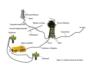
This document provides an overview of subsea pipeline systems. It discusses the key components including wellhead platforms, risers, pipelines, manifolds, and flowlines. It then describes various types of subsea pipelines and their purposes for transporting hydrocarbons from offshore production units to shore. The rest of the document outlines the major design considerations and analyses performed for subsea pipelines, such as sizing, material selection, mechanical design, stability, crossings, and cathodic protection. Standards and codes used for subsea pipeline design are also listed.


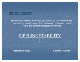
![Vertical stability
Sinking in to the sea bed during maximum fluid density
condition.
Floating of Buried Pipeline during Empty condition Soil
Liquefaction.
The Pipe sinkage is determined as the depth at which the applied
pipe pressure equals the soil bearing resistance.
Soil deformation(pipe sinkage)H,is given by:
sinkage)H
H = D/2-[(D/2)2 ± (B/2)2]1/2
D/2-
Where,
D = Overall pipe outside diameter including pipe coatings
B = Projected contact area between pipe and soil =P/qu
Where,
qu = CNC +1/2BK NK
+1/2BK
qu = Ultimate bearing capacity of soil
P = Pipe submerged weight including pipe coatings and in water
filled condition per unit length.](https://image.slidesharecdn.com/98338181-overview-to-subsea-system-131023214853-phpapp02/85/subsea-20-320.jpg)