This document provides an overview of subsea field development. It discusses key considerations like deep water vs shallow water development, wet tree vs dry tree systems, standalone vs tie-back development, and artificial lift methods. It also covers topics like subsea processing, template and clustered well systems, and daisy chain configurations. The document compares standalone and tie-back developments and outlines the decision process for selecting between the two options.
Overview of subsea field development presented by Dr. M Hamid Siddique, focusing on the lecture's unit details.
An overview of subsea field development, including types, processes, facility selection, and production challenges.
Classification of subsea development into shallow, deep, and ultra-deep water based on depth measurements.
Comparison of wet tree vs. dry tree systems, their installation, suitability based on reservoir geometry, and operational implications.
Further insight into wet tree systems, discussing configurations for subsea wells and efficiency.
Description of subsea tie-back systems, their economic benefits, designs, and flow assurance management.
Key factors affecting tie-back challenges, focusing on cost, safety, environmental impact, and recovery rates.
Evaluation criteria for choosing between stand-alone and tie-back facilities based on economic and operational factors.
Detailed considerations for assessing the viability of stand-alone facilities vs. tie-backs for oil and gas development.
Overview of types of stand-alone facilities including fixed platforms, compliant towers, semi-submersibles, and more.Explanation of artificial lift techniques such as gas lift, subsea boosting, and electric submersible pumps.
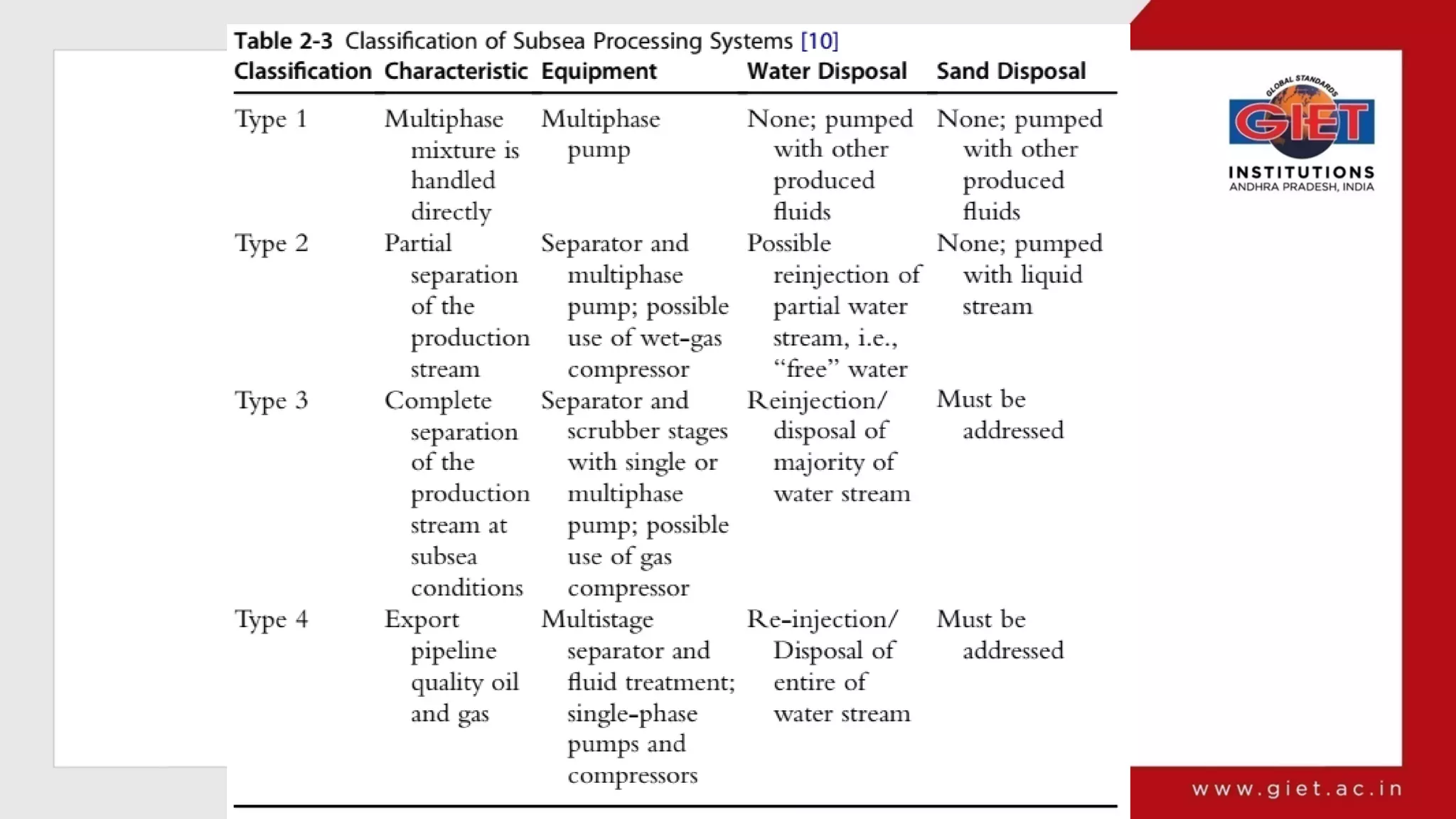
Definition and benefits of subsea processing, including boosting, separation, and its influence on flow assurance.
Various subsea well configurations like satellite systems, clustered well systems, and daisy chains optimizing production.
Subsea Field Development
PresentedBy:
Dr. M Hamid Siddique
Assistant Professor
Petroleum Engineering
GCE, Rajahmundry
Lecture Details:
Unit : Lecture 3
SSE/PET, 4-2
2.
Subsea Field DevelopmentOverview
CONTENTS
• Deep-water or Shallow water development
• Wet Tree & Dry tree systems
• Subsea Tie-back development
• Standalone development
• Artificial lift methods and constraints
• Subsea Processing
• Template, Clustered well system & Daisy Chain
• Subsea field development assessment
3.
Subsea Field DevelopmentOverview
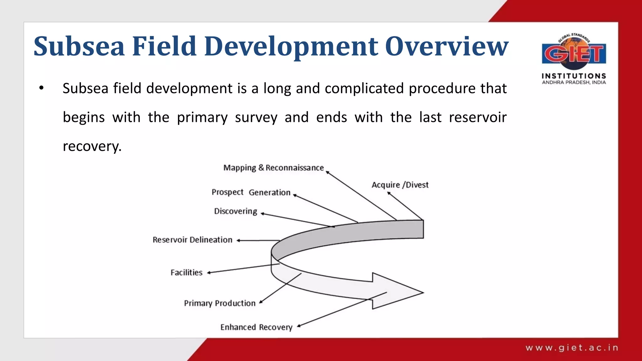
• Subsea field development is a long and complicated procedure that
begins with the primary survey and ends with the last reservoir
recovery.
4.
Subsea Field DevelopmentOverview
• Initially, mapping and reconnaissance are conducted by exploration geologists
and geophysicists.
– They ultimately delineate the development area’s geology based on the data
gathered from old wells, seismic analysis, and any other information that is
available.
– Check for sub-regional features (fold, fault, traps for HC etc.)
– Check for stratigraphy (porosity and permeability)
– The burial history of the basin (About source rock history for HC generation)
• Reservoir description phase (Drilling delineation wells, 3D seismic analysis)
5.
Subsea Field DevelopmentOverview
• Decision on the optimum subsea field layout and pipeline route.
• Selection of production facilities based on field layout and installation
considerations.
• After all well and equipment testing, the field begins to produce oil and gas.
However, as more and more oil and gas are transported to
the host structure from the reservoir, the reservoir pressure will decrease, and
need to recovery to keep the production being transported from the reservoir.
6.
Field architecture
• Deep-wateror shallow-water development;
• Dry tree or wet tree;
• Stand-alone or tie-back development;
• Subsea processing;
• Artificial lift methods;
• Facility configurations (i.e., template, well cluster, satellite wells,
manifolds).
•
7.
Field architecture
• Deep-wateror shallow-water development;
Subsea field development categorized according to the water depth:
• Shallow-water ( less than 200m or 656 ft) i.e. it’s the depth where a
sea diver can reach.
• Deep-water subsea (200-1500m or 656ft to 5000ft)
• Ultra-deepwater subsea (1500 m or 5000ft and above)
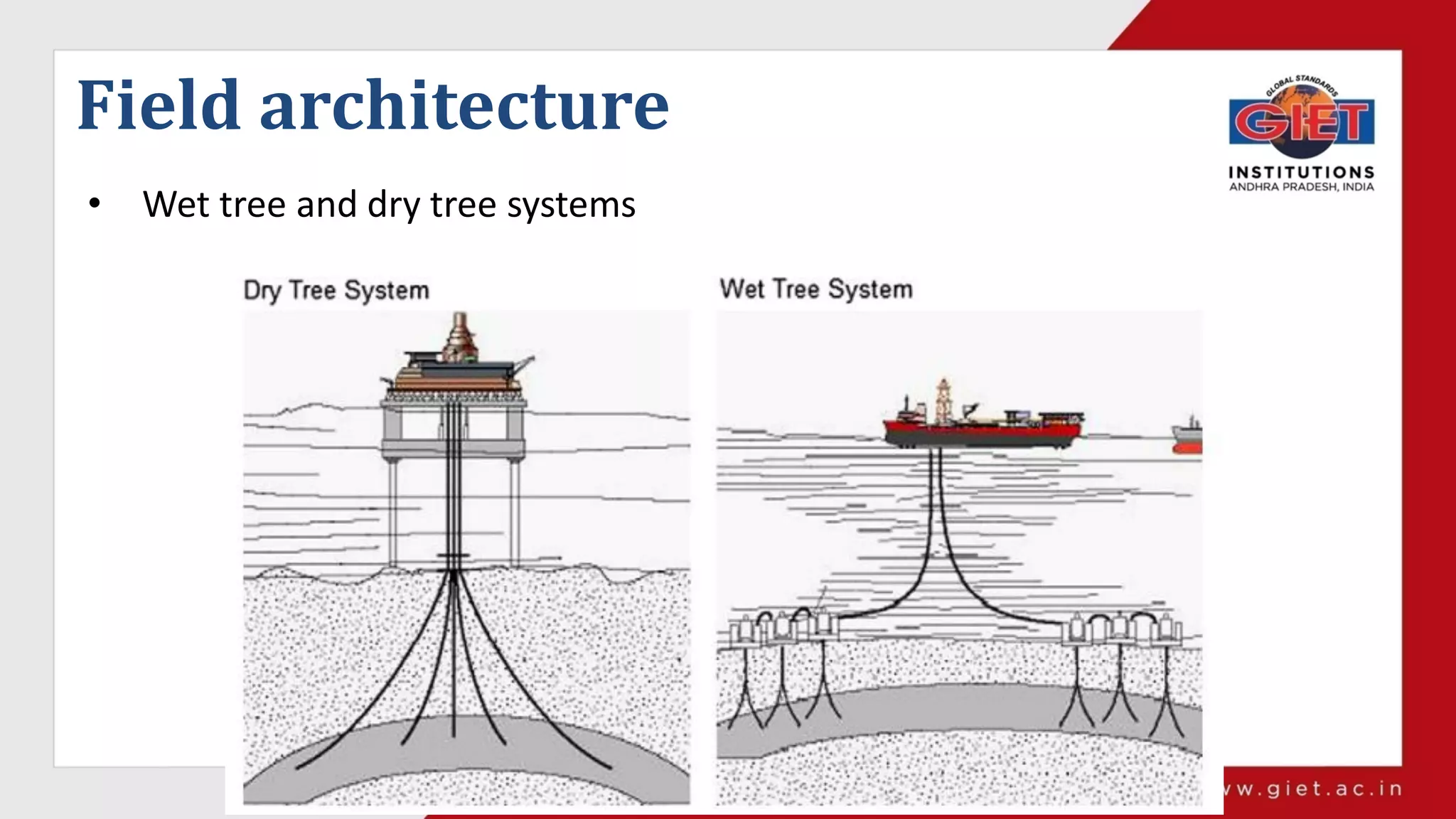
Dry Tree WetTree
Located close to the platform Located anywhere in the field
Used till 500 ft Can be used at any depth
Suitable for reservoir geometry where a
single drilling location can reach all well
locations
Suitable to all reservoir geometries and
areal sizes, and allow increased flexibility
in field layouts, such as multiple
individual wells and multiple drill centers.
The surface tree is installed on the
surface of the production deck
Entire facilities are dipped in water and
control through hydraulic lines.
It limits hull selections to SPARs or
tension leg platforms
Can be used with any hull form, typically
used in conjunction with FPSOs
Minimize flow assurance because of
vertical path.
Change of flow blockage due to long riser
and pipelines
12.
Dry Tree systems
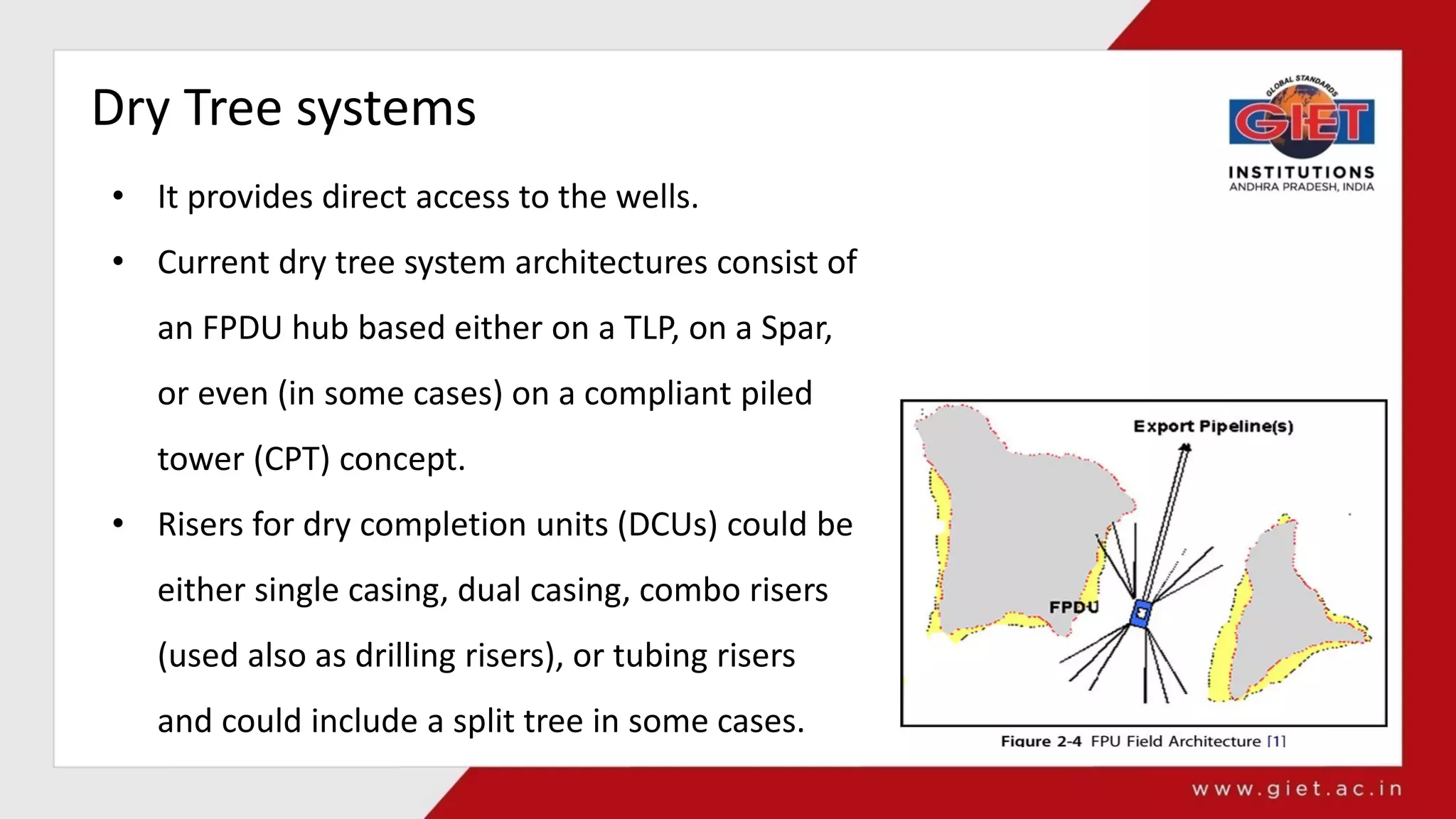
•It provides direct access to the wells.
• Current dry tree system architectures consist of
an FPDU hub based either on a TLP, on a Spar,
or even (in some cases) on a compliant piled
tower (CPT) concept.
• Risers for dry completion units (DCUs) could be
either single casing, dual casing, combo risers
(used also as drilling risers), or tubing risers
and could include a split tree in some cases.
13.
Wet Tree systems
•Wet tree system, the subsea field layout usually comprises two types:
1. Direct access wells,
2. Subsea wells clusters
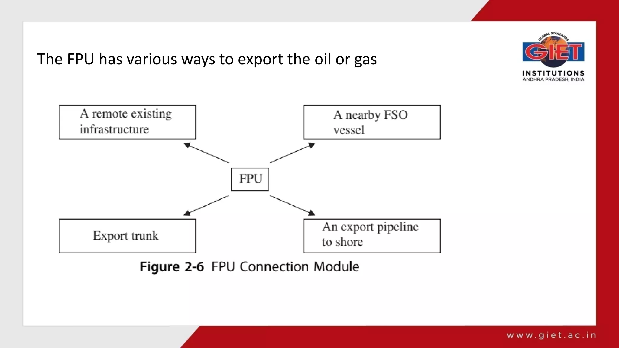
The direct access is less used i.e. usually, based on semi-submersible floating
production and drilling units (FPDUs) with oil export either via pipeline or to a
nearby floating storage and offloading (FSO) unit.
It provide direct and cost effective access from the surface to the wells to allow for
workover or drilling activities directly from the production support, especially for
deepwater interventions.
14.
Wet Tree systems
•Wet tree system, the subsea field layout usually comprises two types:
1. Direct access wells,
2. Subsea wells clusters
A subsea cluster of wells gathers the production in the most efficient and cost-
effective way from nearby subsea wells, or (when possible) from a remote /distant
subsea tie-back to an already existing infrastructure based on either a floating
production, storage and offloading (FPSO) or a floating production unit (FPU),
depending on the region considered.
15.
Subsea well clustersand subsea direct access wells
1. Subsea tie-back system which is normally as a supplement for subsea cluster well
developments.
2. FPU architecture, Typically a barge, semi-submersible, or even a mini-TLP type
vessel is used.
3. FPSO usually utilizes a ship-shaped or barge-type vessel as the host structure that is
moored either via a turret and weathervaning system to allow for tandem
offloading or spread moored with offloading via a distant buoy or still in tandem
mode.
System Selection
• Economicfactors: Estimation of cost and time
• Technical factors: Reservoir depletion plan, location,
operating philosophy, maturity and reliability.
• External factors: project risks, project management,
innovative thinking, operator preferences, and people
18.
Subsea Tie-back Development
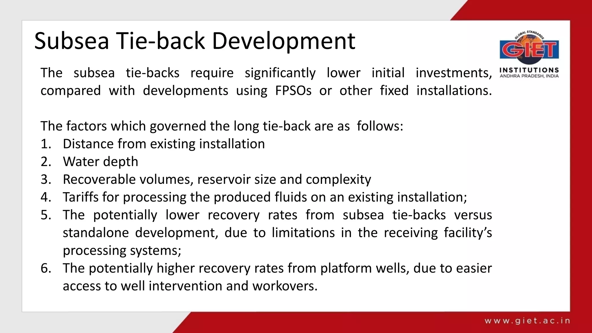
Thesubsea tie-backs require significantly lower initial investments,
compared with developments using FPSOs or other fixed installations.
The factors which governed the long tie-back are as follows:
1. Distance from existing installation
2. Water depth
3. Recoverable volumes, reservoir size and complexity
4. Tariffs for processing the produced fluids on an existing installation;
5. The potentially lower recovery rates from subsea tie-backs versus
standalone development, due to limitations in the receiving facility’s
processing systems;
6. The potentially higher recovery rates from platform wells, due to easier
access to well intervention and workovers.
Tie-Back Field Design
Thedesign and specifications of the subsea flowlines are driven by the
needs of flow assurance management. Flow assurance management
includes ensuring that the unprocessed well fluids:
1. Are able to reach the processing facility;
2. Arrive at the process facility above critical temperatures (such as the
wax appearance temperature or cloud point and the hydrate
creation temperature);
3. Can be made to flow again after a planned or unplanned shutdown
(particularly with respect to clearing hydrate blockages);
4. Avoid hydrates, wax, asphaltene, scale, sand, and other undesirable
contents from building up in the flowline;
5. Can be made to flow at a range of driving pressures, flow rates, and
compositions.
23.
Tie-Back Field Design
Dualflowlines with an end-to-end loop, which are customarily
used for subsea tie-backs, provide a full circuit for the pig so
that the pig can pass through the flowline from the production
platform, through the tie-back flowline, and then back to the
production platform, as shown in Figure.
24.
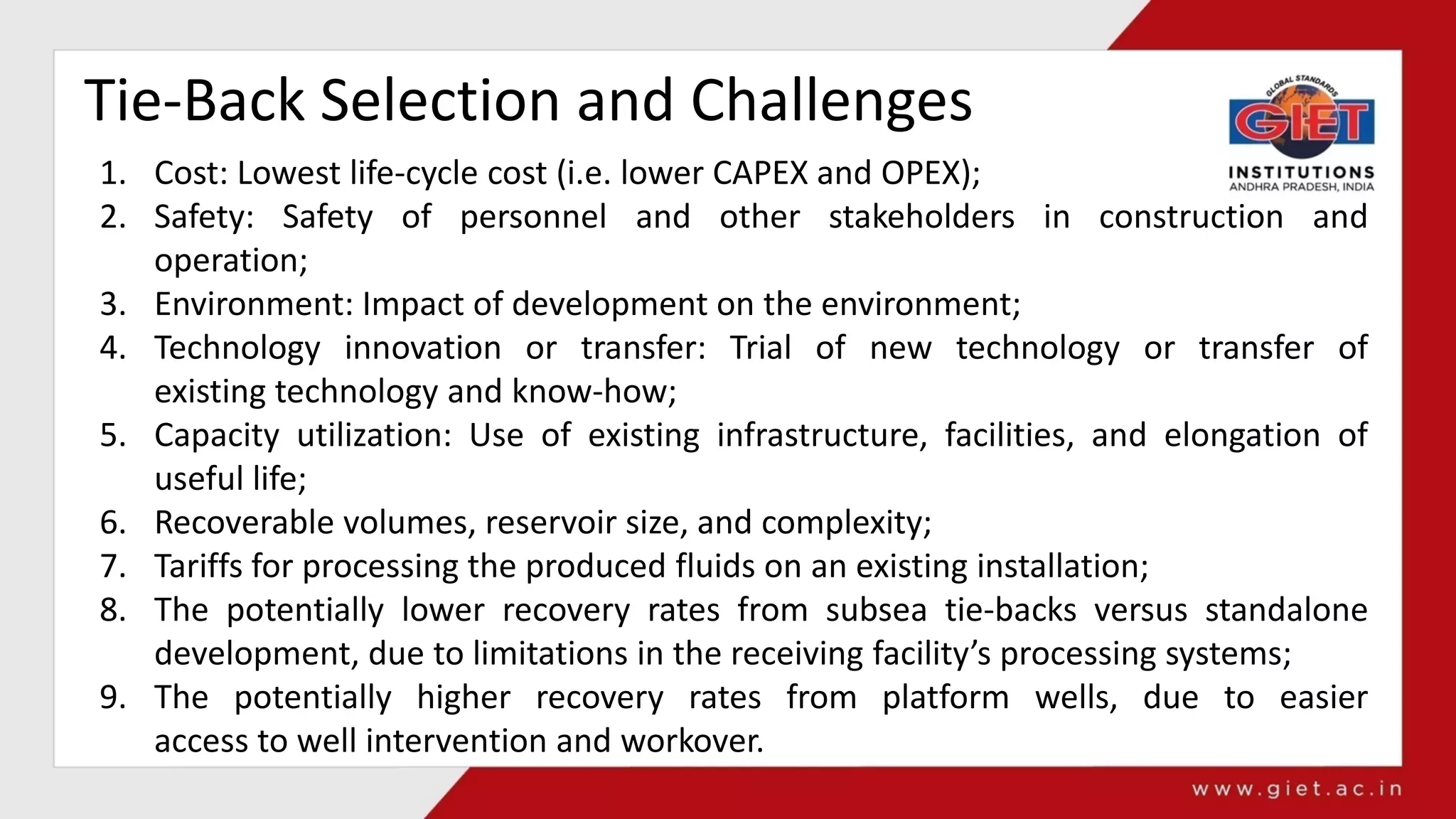
Tie-Back Selection andChallenges
1. Cost: Lowest life-cycle cost (i.e. lower CAPEX and OPEX);
2. Safety: Safety of personnel and other stakeholders in construction and
operation;
3. Environment: Impact of development on the environment;
4. Technology innovation or transfer: Trial of new technology or transfer of
existing technology and know-how;
5. Capacity utilization: Use of existing infrastructure, facilities, and elongation of
useful life;
6. Recoverable volumes, reservoir size, and complexity;
7. Tariffs for processing the produced fluids on an existing installation;
8. The potentially lower recovery rates from subsea tie-backs versus standalone
development, due to limitations in the receiving facility’s processing systems;
9. The potentially higher recovery rates from platform wells, due to easier
access to well intervention and workover.
STAND-ALONE DEVELOPMENT
The decisionto select long tie-backs or a new stand-alone facility can be
based on an overall consideration of various factors:
1. Lowest life cycle cost (i.e., lower CAPEX and OPEX). For the service
provider, the first avenue for cost reduction typically focuses on
CAPEX, specifically the reduction of up-front expenditures related to
materials and equipment;
2. Safety of personnel and other stakeholders in construction and
operation;
3. Impact of the particular facility on the environment;
4. Trials of new technology when subsea tie-backs are used as compared to
the transfer of existing technology and know-how when stand-alone
facilities are used;
5. Use of existing infrastructure and facilities and elongation of useful life
when subsea tie-backs are used;
27.
STAND-ALONE DEVELOPMENT
1. Capacityof the existing installation such as processing facilities, space,
weight, and budget;
2. Recoverable volumes, reservoir size, and complexity. If the recoverable
volume cannot justify the need for a new stand-alone facility, subsea
tiebacks with lower investment can be used;
3. Tariffs for processing the produced fluids on an existing installation;
4. The potentially lower recovery rates from subsea tie-backs versus
standalone development, due to limitations in the receiving facility’s
processing systems;
5. The potentially higher recovery rates from platform wells, due to easier
access to well intervention and workover.
28.
Comparison between theStand-Alone and
Tie-Back Developments
Tie-back projects are an important component of oil and gas production. Advances in
technology have made them less expensive, while the economic advantages of
developing fields by tying them into existing infrastructure are obvious.
Classification of Stand-AloneFacilities
• Fixed Platform: Various types of structure, steel jackets, concrete caisson, floating
steel, and even floating concrete. Economically feasible upto 1700(520 m)
• Compliant towers: These platforms consist of slender flexible towers used as
conventional deck for drilling and production operations. Typically used in water
depths ranging from 1500 to 3000 ft (450 to 900 m).
• Semi-submersible platforms: These platforms have hulls (column and pontoons) of
sufficient buoyancy to cause the structure to float, but of weight sufficient to keep
the structure upright. Semi-submersibles can be used in water depths from 200 to
10,000 ft (60 to 3050 m).
• Jack-up platforms: are platforms that can be jacked up above the sea using legs
that can be lowered, much like jacks. These platforms are typically used in
water depths up to 400 ft (120 m), although some designs can go to 550 ft (170 m)
depth.
33.
Classification of Stand-AloneFacilities
• Floating production systems (FPS): Generally (but not always) in the shape of ships,
equipped with processing facilities. Some variants of these applications, called
FSOs, FSUs, and FPSOs, are used exclusively.
• Tension leg platforms (TLPs): TLPs are floating platforms tethered to the seabed in
a manner that eliminates most vertical movement of the structure. TLPs are used in
water depths up to about 6000 ft (2000 m).
• Spar platforms: Spars are moored to the seabed like TLPs, but whereas a TLP has
vertical tension tethers, a spar has more conventional catenary mooring lines. The
deepest spar, Shell Perdido, located in outer continental shelf blocks in Alaminos
Canyon in the Gulf of Mexico, is installed at an almost 8000-ft (2438-m) water
depth.
34.
Artificial Lift Methodsand Constraints
• The lack of energy in a reservoir can affect the flow rate of oil, gas, or water
and artificial lift is used to supplement the reservoir energy.
• Artificial lifts also boost well production by reducing bottomhole pressure
at wells that are deemed not economically viable.
Basic Artificial Lift Methods
• Gas Lift
• Subsea boosting
• Electric submersible pumps
35.
1. Gas Lift
Theneed of gas lifting is assessed based on the following info:
1. Fluid composition and properties such as solution gas-oil ratio, oil formation
volume factor Oil viscosity, and gas compressibility factor.
2. Maximum water content, etc.
3. Multiphase flow correlations
4. Well profile, production rate data, bottomhole flowing pressure, average reservoir
pressure at mid perforation, and surface gas-lift pressure need to optimize the gas-
lift system.
2. Subsea PressureBoosting
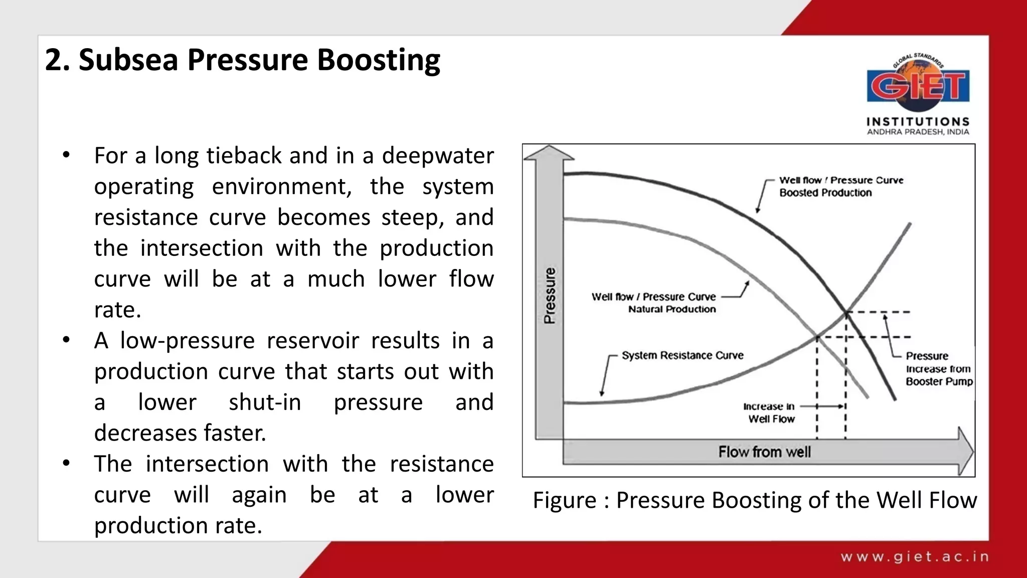
Figure : Pressure Boosting of the Well Flow
• For a long tieback and in a deepwater
operating environment, the system
resistance curve becomes steep, and
the intersection with the production
curve will be at a much lower flow
rate.
• A low-pressure reservoir results in a
production curve that starts out with
a lower shut-in pressure and
decreases faster.
• The intersection with the resistance
curve will again be at a lower
production rate.
39.
2. Subsea PressureBoosting
• Subsea pumps can be used to increase the pressure of the fluid.
• The subsea pump systems are designed to operate for long periods of time
without maintenance. Regular maintenance may be required every 5 years due to
general wear.
• The pumps are of a modular insert design and consist of a driver unit and a
pumping unit.
• Two main booster pump technologies are available, the positive displacement
pump and the centrifugal booster pump.
40.
3. Electric SubmersiblePump (ESP)
• ESP technology is an ideal solution to produce significantly higher fluid
volumes and provide the necessary boost to deliver the production flow to
the host platform.
• The high-volume capacity, wide operating range, and efficiencies up to 40%
higher than the gas-lift process make ESP systems more attractive for
deepwater subsea wells.
• Traditionally, ESP systems are installed downhole.
41.
Subsea Processing
Subsea processing(SSP) can be defined as any handling and
treatment of the produced fluids for mitigating flow assurance
issues prior to reaching the platform or onshore. This includes:
• Boosting;
• Separation;
• Solids management;
• Heat exchanging;
• Gas treatment;
• Chemical injection.
42.
Subsea Processing
The benefitsof introducing subsea processing in a field development could
be:
• Reduced total CAPEX, by reducing the topside processing and/or
pipeline CAPEX;
• Accelerated and/or increased production and/or recovery;
• Enabling marginal field developments, especially fields at deepwater/
ultra-deepwater depths and with long tie-backs;
• Extended production from existing fields;
• Enabling tie-in of satellite developments into existing infrastructure by
removing fluid;
• Handling constraints;
• Improved flow management;
• Reduced impact on the environment.
43.
Subsea Processing
1. Subseaboosting, is one means of increasing the energy of the system.
2. Subsea separation can be based either on two- or three-phase separation:
• Two-phase separators are used for separation of any gas–liquid system
such as gas–oil, gas–water, and gas–condensate systems.
• Three-phase separators are used to separate the gas from liquid phase
and water from oil.
45.
TEMPLATE, CLUSTERED WELLSYSTEM, AND DAISY CHAIN
Subsea production equipment can be configured in multiple ways based
on the field specifications and operator’s approach to operation.
1. Satellite well system
2. Template and Clustered Well System
46.
1. Satellite WellSystem
• Satellite wells are typically
used for small developments
requiring few wells.
• Often the wells are widely
separated and the
production is delivered by a
single flowline from each
well to a centrally located
subsea manifold or
production platform.
47.
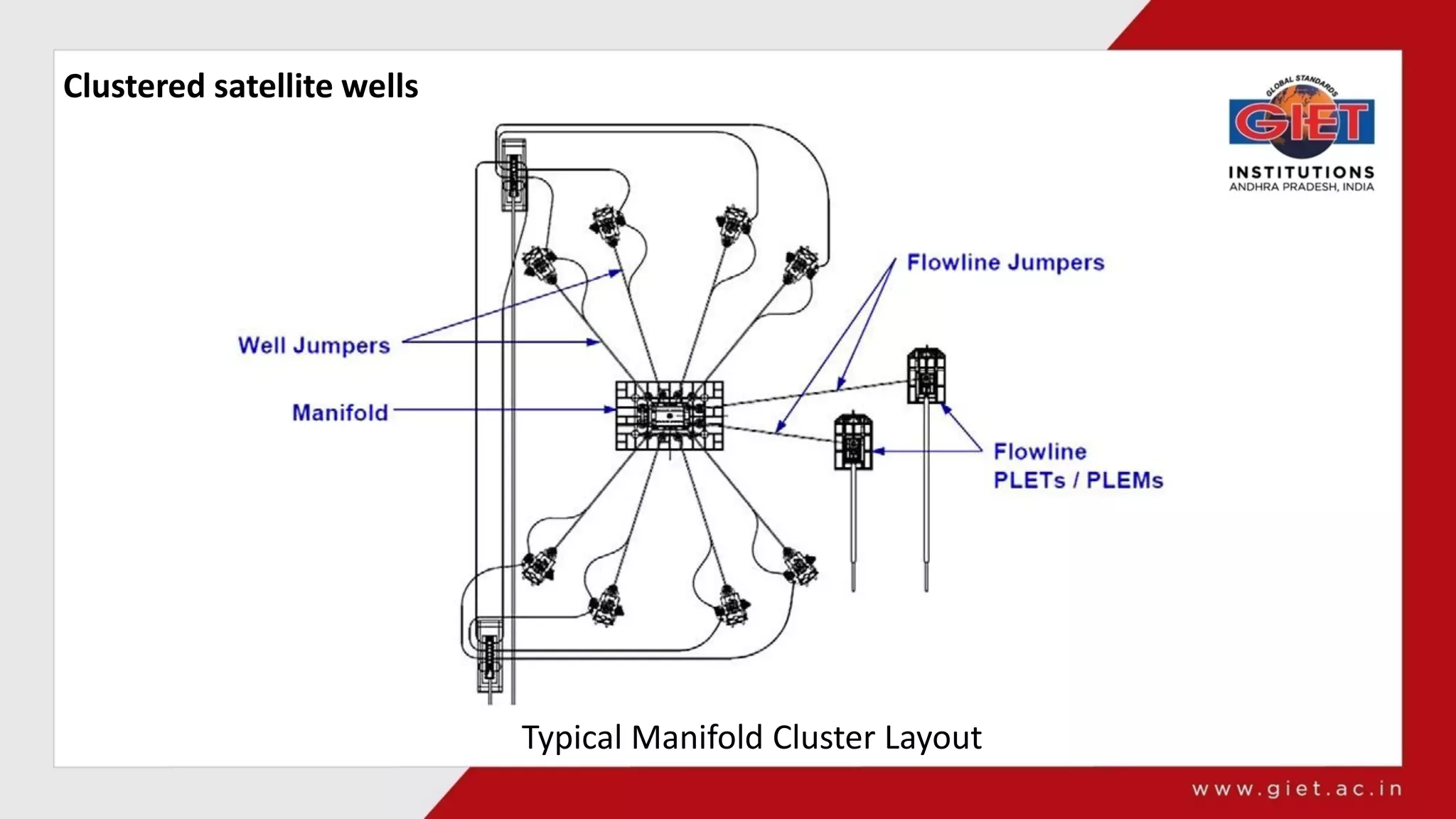
2. Template andClustered Well System
• If subsea wells can be grouped closely together, the development cost will
usually be less than that for an equivalent number of widely dispersed
wells.
• Well groupings may consist of satellite wells grouped in a cluster, or a well
template, in which the well spacing is closely controlled by the template
structure.
Production well templetes
•Its an another way of clustering wells is by means of a well template.
• Well templates are structural weldments that are designed to closely
position a group of well conductors. Well templates may support two
wells or more than a dozen wells.
• Apart from reservoir considerations, the number of wells in a well
template is only limited by the size of the well template that can be
handled by the installation vessel.
• Small templates are usually deployed from the drilling rig.
• Larger ones may require a special installation vessel with heavier lift
capacity or better handling characteristics.
51.
Production well templetes
Thefollowing are some benefits of production well templates as
compared to clustered satellite wells:
• Wells are precisely spaced.
• Manifold piping and valves can be incorporated.
• Piping and umbilical jumpers between the trees and manifolds may be
prefabricated and tested prior to deployment offshore.
Piping and umbilical interfaces are less expensive than for clustered
wells.
• Installation time is reduced by modularizing much of the equipment.
• Short flowline piping distances (compared to a cluster) reduce the
problems associated with flow assurance (e.g., wax and hydrate
formation) and the need for extensive pipe insulation.
• Horizontal loads imposed by drilling can be taken by the template
structure as opposed to the tree and conductor in the case of a satellite
well.
52.
Production well templetes
Thefollowing are some disadvantages of production well templates as
compared to clustered satellite wells.
• Design and fabrication time may be longer due to greater complexity.
• There may be safety concerns related to simultaneous drilling and
production operations.
• Heavy templates may be more susceptible to subsurface instability, such
as shallow-water flows.
• There is less flexibility in determining well locations.
• ROV access may be limited due to space constraints.
53.
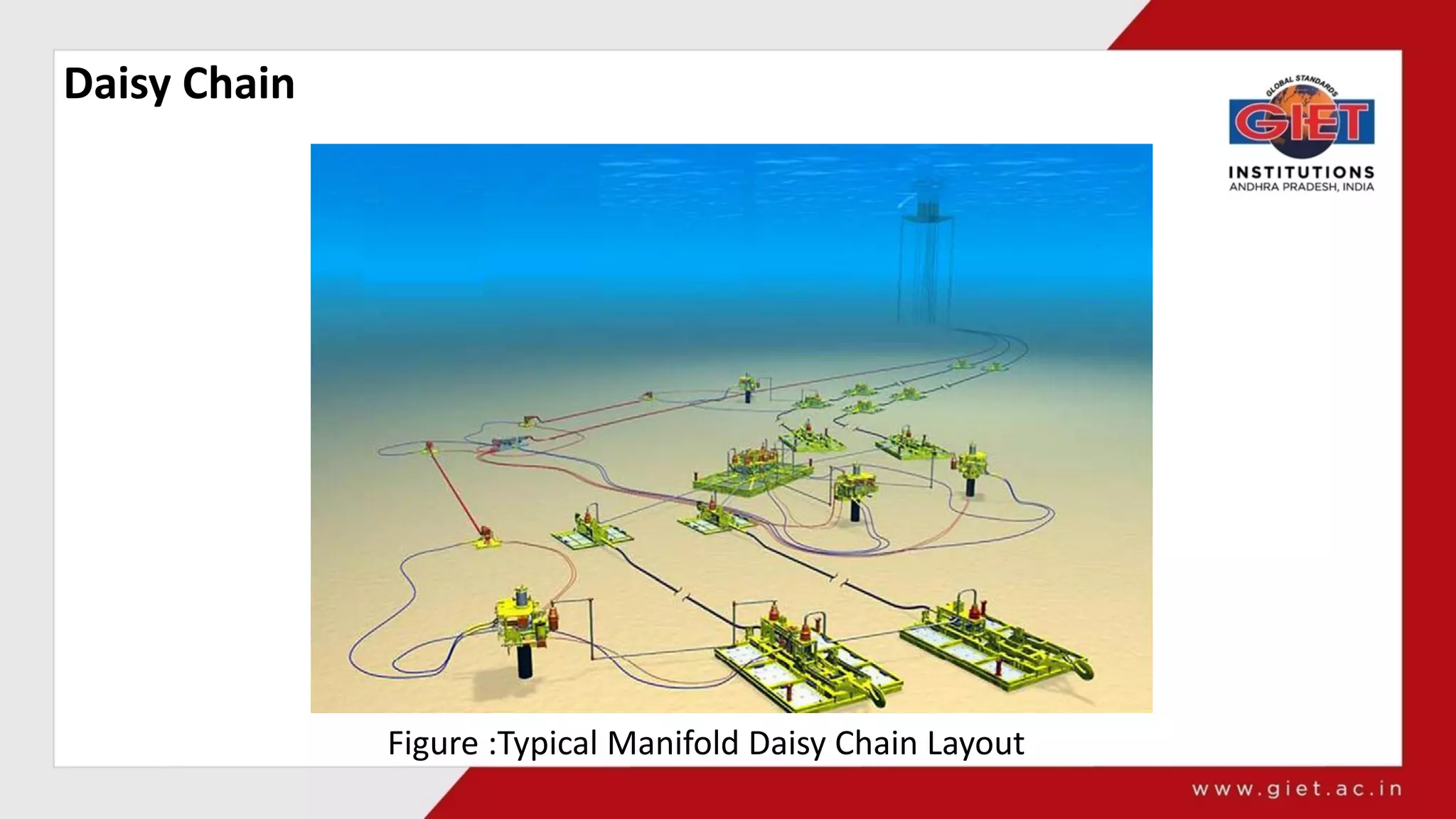
Daisy Chain
• Thedaisy chain subsea wells consist of two or more subsea satellite wells
joined by a common flowline (and possibly umbilical in series).
• Each subsea tree may have a choke installed to avoid pressure
imbalances in the flows.
• Using daisy-chained wells allows for the combined use of infield flowlines by
more than one well, and may provide a continuous loop for round-trip
pigging if needed.
• By arranging wells in a daisy-chained loop, operators can better utilize the
flowlines to the two completions. The dual flowlines provide the capability
for:
• Round trip pigging;
• Diverting both production flows into a single flowline if the second is
damaged;
• Individually testing the two wells whenever needed through
independent lines.
Assignment No. 1
1)Explain different type of booster stations in in subsea production
development.
2) What do you mean by subsea field development assessment?