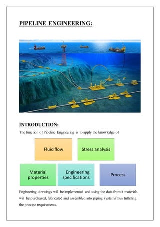
This document summarizes a study report on offshore pipeline engineering completed by Kaarthik Saravanan as an intern at McDermott Middle East Inc. in Dubai from June to July 2016. The report provides an overview of pipeline engineering for offshore oil and gas projects, including the design process, materials selection, and typical offshore structures like platforms, jackets, risers, and tie-ins used for pipeline transportation.
Subsea Field Development for an ideal Green field.Emeka Ngwobia
• The Daiyeriton Field is a green field development project. The subsea field layout with its drill centers has been illustrated in slide 2. New flowlines and pipelines will tie-in to the existing Daiyeriton floating production, storage, and offloading (FPSO) vessel. The new system will enable the transportation of production and injection fluids to and from the Daiyeriton field facilities from five new drill centers: DC-SW, DC-NW, DC-SE, DC-NE and DC-E. DC-SE, DC-SW, DC-NE and DC-E are dedicated production drill centers while DC-NW is a dedicated WI drill center. Gas lift will be provided at the riser base of a new 12-inch production flowline.
•The water depth at the proposed development sites range from 800 m to 1000 m.
This document provides an overview of subsea pipeline systems. It discusses the key components including wellhead platforms, risers, pipelines, manifolds, and flowlines. It then describes various types of subsea pipelines and their purposes for transporting hydrocarbons from offshore production units to shore. The rest of the document outlines the major design considerations and analyses performed for subsea pipelines, such as sizing, material selection, mechanical design, stability, crossings, and cathodic protection. Standards and codes used for subsea pipeline design are also listed.
This document provides an overview of subsea field development. It discusses key considerations like deep water vs shallow water development, wet tree vs dry tree systems, standalone vs tie-back development, and artificial lift methods. It also covers topics like subsea processing, template and clustered well systems, and daisy chain configurations. The document compares standalone and tie-back developments and outlines the decision process for selecting between the two options.
Royal IHC (IHC) is focussed on the continuous development of design and construction activities for the specialist maritime sector. It is the global market leader for efficient dredging and mining vessels and equipment – with vast experience accumulated over decades – and a reliable supplier of innovative ships and supplies for offshore construction.
IHC has in-house expertise for engineering and manufacturing integrated standard and custom-built vessels, advanced equipment and also providing life-cycle support. This integrated systematic approach has helped to develop optimum product performance and long-term business partnerships.
The company’s broad customer base includes dredging operators, oil and gas corporations, offshore contractors and government authorities.
Technological innovation will remain the company’s underlying strength through its continuous investment in research and development. Moreover, it helps to safeguard a sustainable environment.
MCS is a leading provider of advanced subsea engineering and software solutions to the offshore oil and gas industry. It has over 25 years of experience working on projects globally and employs over 220 people across 5 continents. MCS's services include riser and mooring engineering, subsea and pipeline engineering, subsea integrity management, drilling and intervention engineering, and delivery management. It has expertise in deepwater, HPHT, and cyclonic environments.
ottobre 2016 - articolo Saipem bollettino SPEAndrea Intieri
This document provides an overview of flexible pipe and umbilical laying systems used in the offshore oil and gas industry. It describes the main components of flexible laying systems, including storage systems like reel hub drives and carousels, product handling systems, and horizontal and vertical laying systems. It highlights some of the capabilities of state-of-the-art flexible laying vessel Normand Maximus, including its 550 tonne vertical laying system and under deck storage basket.
This document provides an overview of FPSO (floating production storage and offloading) vessel design and systems. It discusses the key components of an FPSO including the hull, mooring systems, fluid transfer systems, topside process facilities, marine systems for cargo handling and offloading, and support utilities. The document focuses on turret mooring systems as the predominant mooring type used on FPSOs and how they enable weathervaning and fluid transfer between subsea infrastructure and the topside processing facilities.
The document discusses the challenges of developing offshore oil and gas fields, particularly in deep waters and remote locations. It notes that while offshore development technologies have enabled projects in up to 3,000m of water, developing fields in ultra-deep waters and frontier regions requires further technological advances. Specifically, it focuses on the need for high-capacity pipe-lay vessels using J-lay or reel-lay methods to install thick-walled pipes in these challenging environments, with each method having advantages depending on the characteristics of the specific field development project. Saipem's new flexible lay and construction vessel, the Normand Maximus, is presented as an innovative vessel designed to aid in ultra-deep water SURF installation and field
The document discusses FPSO layout and turret design. It explains that the key considerations for FPSO layout include cargo capacity, equipment location, hull structure, and integration of marine and topside systems. Internal turrets are suitable for deep water and large numbers of risers, while external turrets eliminate the need for a CALM buoy but risk slamming in large waves. Choosing between internal and external turrets depends on factors like water depth and wave height. An internal turret's position varies along the vessel length depending on its active stationkeeping abilities.
This document provides an overview of offshore oil and gas production systems. It describes the major components which include wells, platforms, pipelines and processing facilities. It outlines different types of offshore platforms suited for varying water depths, such as fixed steel structures, compliant towers, jack-up platforms and floating production systems. It discusses the crews and roles required to operate offshore platforms. It also summarizes fire and explosion protection systems, environmental protection measures, and how supervisory control and data acquisition (SCADA) systems are used to remotely monitor wells.
This document provides a summary of Chinmoy Pathak Choudhury's winter internship at Indian Oil Corporation Limited's Bongaigaon Refinery from January 2nd to January 17th, 2013. It discusses various occupational safety and health hazards in the construction industry and their solutions. Specific hazards covered include scaffolding, fall protection, hazard communication, stairways, ladders, trenching, and cranes. It also provides safety checklists for proper use of personal protective equipment like eye and face protection, foot protection, and hand protection. The document contains three chapters, with the first chapter focusing on occupational safety and health in construction, the second on structural welding, and the third on storage of cement bags in a warehouse
Anteneh Getachew Kebede has over 15 years of experience managing water resource engineering projects in Ethiopia. He has worked on projects such as dams, water treatment plants, pipelines, and hydropower stations. Currently, he owns three construction and trading companies and serves as a general manager and project engineer on water infrastructure projects. He holds degrees in water resource engineering and qualifications as a professional engineer in Ethiopia.
This document discusses subsea marine operations related to oil and gas extraction including:
1) Piping layout and design for transporting fluids from subsea locations.
2) Installation of umbilicals and cables to supply control and chemicals to subsea wells.
3) Tie-in operations to connect pipelines from subsea structures to platforms without using divers.
4) Positions in high demand include piping designers and subsea engineers.
Marginal offshore production platform feasibilityguest651e92c
Final presentation of a feasibility study performed this year (2009) covering many aspects of marginal platform design, fabrication, transport and installation.
This document provides information about an upcoming 4-day training course on FPSO and FLNG design and technology. The course will be conducted from May 23-26, 2016 in Singapore by two experienced instructors. It will cover key technical aspects of FPSO and FLNG design projects, including topside and subsurface systems, regulatory standards, and case studies. Past participants found the training to be informative and beneficial for their work in the floating production industry.
FPSOs are floating production, storage, and offloading systems used in offshore oil and gas production. They are converted tankers that produce hydrocarbons, store them onboard, and then offload them to shuttle tankers for transport to shore. FPSOs typically have oil and gas processing equipment, storage tanks, living quarters, and mooring or dynamic positioning systems to remain on location. Produced liquids and gas are transferred from subsea wells to the FPSO where they are separated, stored, and offloaded to tankers for transport to shore.
The document provides a curriculum vitae for Mikael Struer Kirkegaard summarizing his qualifications and over 30 years of experience in naval architecture, marine, offshore, and subsea engineering. He has worked on numerous projects around the world involving design, construction, quality assurance, inspection, analysis, and project management. His experience includes roles with companies such as Maersk Contractors, DNV, BG Group, Inpex Australia Operations, and Bumiarmada.
Ronald Smith has over 50 years of experience in structural, civil, mechanical, piping, and subsea engineering for the oil and gas industry. He has worked on numerous subsea projects around the world, taking on roles such as lead engineer, senior engineer, and designer. His experience includes work on subsea manifolds, pipelines, risers, production systems, and development studies.
This document discusses the design and operation of topside processing facilities for gas fields. It begins by describing different types of gas field topsides, including fixed jacket platforms, compliant towers, tension leg platforms, spars, semi-submersibles, and floating production storage and offloading vessels. It then covers the design engineering process for topsides, including the FEED and detailed engineering phases. Finally, it discusses factors to consider in the design of offshore processing facilities, such as minimizing liquid misdistribution and designing for LNG storage and offloading.
Mooring analysis involves designing an offshore mooring system to withstand extreme environmental conditions like 100-year storms. Key factors in the mooring layout include the strength of each mooring line, seabed topography, and directions of wind, waves and currents. Common mooring patterns are distributed to balance loads and provide redundancy. Analysis calculates line tensions and vessel excursions in storms, traditionally analyzing mooring and risers separately but now integrated. The purpose is to ensure the vessel stays within acceptable distance limits under worst loads.
Umair Khaliq is an engineering geologist with over 6 years of experience in tunnel engineering, geotechnical investigations, and construction supervision. He has worked on several hydropower and infrastructure projects in Pakistan, including the Gulpur Hydropower Project and Neelum-Jhelum Hydropower Project. His responsibilities have included tunnel instrumentation, geological mapping, geotechnical analysis, and supervision of tunnel construction activities like rock bolting and shotcrete installation. He has strong skills in geological and geotechnical software as well as project report writing.
This document appears to be a project report for designing a sump well with a capacity of 200 kl at the NRI campus in Bhopal, India. It includes sections on introduction, campus details, water requirements, design of the sump well, pump house, and various cost estimates. The project involves designing critical water infrastructure for the campus including a sump well to store water, meeting the daily water needs of the campus population.
This document outlines the expertise of a course director including managing pressure drilling systems, multilateral wells, and coiled tubing underbalanced drilling. It also lists equipment and activities related to geophysical well logging, underreaming, cement plug placing, fishing operations, risk analysis, coiled tubing equipment, nitrogen application, separation systems, and management/control systems for drilling operations.
This document provides an overview of different types of offshore structures used in oil and gas exploration. It discusses jack-up rigs, semi-submersibles, drill ships, concrete platforms, jacket platforms, tension leg platforms, wellhead platforms, floating production storage and offloading (FPSO) systems, spar platforms, subsea production systems, guyed towers, and shuttle tankers. Each structure is described in 1-2 paragraphs outlining its key characteristics and applications. The document also provides a high-level introduction to designing offshore structures and considering factors like loads, specifications, and stability in deep waters.
Spencer Atkinson has over 33 years of experience in ship repair, refit, conversion, and engineering in both commercial and naval markets. He has extensive experience managing projects, estimating costs, negotiating contracts, planning work, overseeing subcontractors, and ensuring projects are completed on time and on budget. His most recent and largest project was managing the £47 million refit of the RFA Fort Victoria from 2013-2015, which involved overseeing 450 workers and 350 subcontractors across 59 specification areas.
Romeo Costescu is a principal structural engineer from Norway with over 30 years of experience. He has extensive experience performing structural analysis and design work for offshore oil and gas projects. His areas of expertise include finite element analysis, structural analysis and design, pipe stress analysis, lifting and transportation analysis, and project management. He is proficient in various analysis software like ANSYS, LS-DYNA, ABAQUS, and is seeking a new engineering challenge.
The basic principle behind any hydraulic system is Pascal's Law. "Pressure applied anywhere to the body of fluid causes a force to be transmitted equally in all directions, with the force acting at right angles to any surface in contact with the fluid."
Este documento resume la estructura de almacenamiento utilizada por los sistemas operativos. Explica que la memoria principal es la más rápida pero no lo suficientemente grande para almacenar todos los programas y datos, por lo que utiliza segmentos para la memoria de texto, datos y pila. También describe la memoria secundaria como más lenta pero de mayor capacidad, como los discos duros. Finalmente, introduce la memoria terciaria como la más lenta y de almacenamiento fuera de línea.
This document provides a summary of Johnathan Broady's qualifications including his education, awards, technical experience, publications, memberships, and teaching experience. He holds an M.S. in Animal Sciences from Auburn University and a B.S. in Biology from Washington State University. Currently he works as the Food Safety Superintendent at JBS Souderton plant where he oversees food safety audits and liaises with the USDA. He has extensive experience in food safety and microbiology research.
Net Present Value (NPV) is a method used to analyze the profitability of a capital project by discounting the future cash flows to their present value. NPV is calculated as the difference between the present value of cash inflows and the present value of cash outflows. Costs that should be included in an NPV analysis are capital expenditures and operational costs directly attributable to the project, with index costs if greater than one year. Costs like depreciation and overhead allocation should be excluded from the NPV calculation. A clear process with quotes, workings, and an NPV calculation with references is important for an accurate analysis.
This document provides information on Abhay Ocean India Pvt Ltd, a company that specializes in marine engineering projects such as submarine pipelines, marine intakes/outfalls, and dredging. It details the company's experience with various marine outfall projects. It also outlines the scope of work for a proposed sea water intake and reject outfall system for a desalination plant, including surveying, designing, supplying, installing, and testing the submarine pipelines and intake/diffuser structures.
Daniel Cobar is applying for the position of Lead Pipeline Engineer. He has over 15 years of experience in pipeline design, construction, and commissioning for both offshore and onshore projects around the world. Some of his project experience includes working on the Caspian Sea Pipeline Expansion Project and the Angola LNG Project. He has extensive knowledge of pipeline codes and standards and software like MicroStation, AutoCAD, and CAESAR II.
This document provides a summary of Hafeeda V's qualifications and experience as a pipeline engineer. She has over 2.5 years of experience in flexible pipe design and analysis. She is proficient in technical software such as Orcaflex, AutoCAD, Mathcad, PLAXIS, DEEPSOIL and Siesmosoft. She has worked on numerous offshore pipeline projects in her role at Technip India Limited and is seeking a new position as a subsea or offshore engineer.
The document outlines several projects the author worked on between 1997-2009:
1) Between 2009-2008, the author managed decommissioning of oil platforms and fiber optic cable laying projects.
2) In 2006, the author managed projects involving life of field seismic installation for BP, including gravity base design.
3) Between 1997-2002, the author managed various subsea installation projects for umbilicals, drilling templates, and wet buckle repair systems.
4) The author has experience managing trenching systems and working on numerous construction and pipe-lay vessels.
Jundee Mar Tejedo has over 10 years of experience as a QA/QC Engineer and Civil Engineer in Qatar and the Philippines. He has extensive experience managing construction projects, including roads, infrastructure, grading works, and more. He is proficient in quality control, project coordination, resource management, and ensuring safety and regulatory compliance. Tejedo holds a Bachelor's degree in Civil Engineering and is a licensed Civil Engineer in the Philippines.
DESIGN OF A MODEL HAULAGE TECHNIQUE FOR WATER FLOODING CAISSON ASSEMBLY.Emeka Ngwobia
Presented in this study is the engineering solution to the movement of a 63m, 45tons Caisson from a fabrication yard to a field location in the Gulf of guinea. This was achieved by dividing the whole process into three stages; firstly by using excel sheets with relevant design formulas to design the spreader bar configuration to lift the caisson from the quayside to a crane barge conveniently, showing the necessary lifting sequence employed to complete this process, also designing the lifting accessories needed which includes pad eyes, shackles, wire rope and spreader bars according to relevant codes and standards The first spreader Is an I beam of length of 25m and section with dimension 533mm by 229mm weighing 129kg/m, the second beam and the third beam are designed similarly as an I beam of length 9m and section 533mm by 229mm weighing 129kg/m. The choice of pad eye to be welded on the spreader beam was based on the working limit of the pad eye, which was analytically designed using spread sheet, performing necessary checks to make sure it will not break off during the lifting operations. It is reinforced with cheek plates at the pin hole to reduce the stresses at the pin hole. The total pad eye used for this operation is 16. The choice of shackle attached to each of the pad eye was based on the total self weight of all the lifting materials(55tons), according to the Crosby group catalogue it is an S2130 bow shackle of Nominal size 50.8mm, Stock no 1019659 and weight 23.7002kg, also the wire rope configuration chosen to based on the safe working load limit according to the Bethlehem wire rope general purpose catalogue ASME B30.5- 1995 the wire rope has nominal strength of 53.1tons, sling class 19x7 IWRC(Purple or extra improved ploy (EIP Steel).
. Secondly, by providing solutions to sea fastening for the caisson on the deck of the crane barge, which was modeled using STAADPRO, which involved support designs and loss of support designs, so as to accommodate for the hydrodynamic effect while the caisson is being transported by the crane barge, having in mind that the crane barge chosen will adequately accommodate the caisson because of the deck space required to fit the 63m long caisson, from the analysis the Caisson is supported by steel beams spaced at 10 m interval which is fastened with the aid of a clamp as seen in the detailed drawings, this caisson and beam supports are modeled with staadpro software and support reactions obtained. These supports are now spaced at 20 m intervals and analyzed to simulate a situation where there is a loss of support reaction during transportation of the caisson. A saddle clamp is to joined to a H beam for support to hold it to the deck at varying length and at the starting point a pivot made from a pad eye joined with a pin to connect the saddle clamp to allow for easy lifting of the caisson when it is at 25m to the FPSO.
This document provides an analysis of a typical offshore bridge connecting adjacent offshore platforms. It begins with an introduction to offshore oil and gas exploration and production. It then describes the types of structures used in offshore development like wellhead platforms, process platforms, and living quarters platforms. The types of offshore structures are categorized into bottom fixed structures, floating structures, and subsea systems. Bottom fixed structures include jackets, compliant towers, and gravity-based structures. Floating structures include spar platforms, tension leg platforms, floating production systems, and floating production, storage, and offloading units. The document outlines the preliminary requirements for designing offshore structures like platform geometry, concept selection, and types of loads on the platform including gravity loads and environmental loads.
The document provides information on the key aspects of planning and constructing a cross-country pipeline project. It discusses surveying the route, acquiring rights-of-way, assembling and welding pipe sections, lowering the pipe into the ground, installing valves and crossing structures, backfilling trenches, testing the pipeline integrity, and implementing cathodic protection. The overall process involves detailed engineering design, procurement, and managing construction to safely deliver bulk fluids across long distances via an underground pipeline system.
Meshak's CV provides information on his qualifications and experience as an NDT Inspector. He has over 4 years of experience in non-destructive testing for the marine, offshore, and onshore oil and gas industries. He holds professional certifications from BINDT and ASNT and has worked on projects for clients like Shell, SBM Offshore, and Keppel Shipyard. He has specialized experience performing ultrasonic testing on welds, pipes, vessels, and other equipment.
Meshak's CV provides information on his qualifications and experience as an NDT Inspector. He has over 4 years of experience in non-destructive testing for the marine, offshore, and onshore oil and gas industries. He holds professional certifications from BINDT and ASNT and has worked on projects for clients like Shell, SBM Offshore, and Keppel Shipyard.
Remotely Operated Vehicles (ROVs), A Subsea EnablerAhmed Abo Bakr
A brief of my Udemy Course: Remotely Operated Vehicles (ROVs), A Subsea Enabler
Discovering The Deepwater World Made Possible, With a Focus on the Petroleum Engineering (Oil and Gas Industry)
If you like the slides, you can find the full course on Udemy here: https://www.udemy.com/course/remotely-operated-vehicles-rovs-a-subsea-enabler/?referralCode=AE53ABB765F1B8FD2F27
Unlock the mysteries of Remotely Operated Vehicles (ROVs) with this comprehensive course based on my book "Remotely Operated Vehicles (ROVs): Current Systems, Future Trends, and Operational Challenges" available on Amazon.
Discount Offer:
*Reach out to me on LinkedIn for a Special Discounted Rate for University Students!*
This course coupled with the Summary Q & A and practice questions shall take you on a step-by-step journey to learn more and more about ROVs, covering the following main concepts:
Module 1: Understanding ROVs
-Historical Background and Maturity
-ROV Classifications
-Applications and Capabilities
-ROV Systems, Components, and Tooling
Module 2: ROV Trends
-Resident ROV (RROV) and Empowered ROV (EROV)
-Benefits, Working Principles, and System Challenges
-AUV System Components and Levels of Autonomy
-Virtual Reality (VR) and Augmented Reality (AR)
-Hybrid Solutions
Module 3: Challenges and Opportunities
-Reliability and Maintainability
-Addressing Poor Visibility and Weather Dependency
-Tackling Lost and Malfunctioned Vehicles
-Safeguarding Against Security Threats
Module 4: ROV Professionals Survey
-Methodology and Approach
-Survey Questions and Results Discussion
-Operational and Safety Challenges
-Incidents and Near Misses
What You Will Learn:
-An in-depth knowledge of ROV systems, subsystems, and components.
-Explore ROV tooling and understand its applications.
-Stay updated on the latest ROV trends and recent developments.
-Address challenges faced by Resident ROV (RROV) and Empowered ROV (EROV) systems.
-Understand AUV system components and their main operations.
-Identify and overcome challenges, opportunities, and threats in underwater vehicles.
-Gain insights from a survey of ROV professionals, including pilots, engineers, and industry representatives.
Why Enroll:
This course provides a step-by-step journey through the fascinating world of ROVs. Whether you are a student, engineer, or industry professional, this course equips you with the knowledge and skills needed to navigate the complexities of underwater vehicles.
Don't miss the chance to explore the depths of ROV technology! Enroll now and understand this field.
Paul M. Wilson is a subsea and drilling engineer with over 16 years of experience in subsea operations including structural engineering, equipment design and installation, and underwater data collection. He has worked for various companies conducting inspections, surveys, and engineering work on offshore rigs and equipment in locations around the world. Wilson also has 17 years of experience in the US Marine Corps conducting covert operations.
Roy Shilling has over 37 years of experience in deepwater oil and gas engineering. He has extensive project experience in floating and riser systems design, analysis and fabrication. Currently, he works as a consultant providing engineering support through his company Frontier Deepwater Solutions. Some of his current projects include evaluating wet tree vs. dry tree development options for Anadarko's Shenandoah field and qualifying equipment for Chevron's 20K development.
The document provides a resume for Salimon Puthuparambil Hassan applying for a Mechanical Engineer position, outlining his educational background which includes a Bachelor's degree in Mechanical Engineering, over 20 years of experience in facility maintenance and engineering roles in India, Saudi Arabia, and Qatar, and qualifications in areas like HVAC, boilers, piping, and oil and gas facilities.
An offshore platform is a large structure used to house workers and machinery needed to drill and/or produce natural resources through tunnels/wells in the ocean bed. There are several types of offshore platforms including fixed platforms, compliant towers, semi-submersible platforms, jack-up platforms, and drillships. Fixed platforms can be steel jacket structures anchored to the seabed or large concrete structures that sit on the seabed through their massive weight. Semi-submersible platforms float but have large pontoons to keep them stable, while jack-up platforms have legs that can be lowered to the seabed to raise the drilling structure above water.
A subsea completion involves installing well equipment on the seafloor such that the producing well does not have a vertical conduit back to a fixed offshore structure. It consists of a production tree, upper completion connecting the tree to the lower completion, and a lower completion installed across the producing intervals. Subsea completions provide environmental and economic benefits over other offshore development alternatives in deep waters. However, their success relies on maintaining production over time without interruptions, which requires addressing regulatory, safety, economic, technological, and environmental factors.
This document provides an overview of petroleum drilling fundamentals, including different types of rigs used for offshore drilling. It discusses jack-up rigs, semi-submersible rigs, drill ships, condeep platforms, jacket platforms, and tension leg platforms. It also covers well planning, designing the well, drilling operations, completions, new technologies, and structural geology. Key steps in drilling include obtaining licenses, exploration, appraisal, development, maintenance, and abandonment of oil and gas fields. Safety and monitoring drilling progress are also emphasized.
Mabro Engineering and Technical Services is a South African company that provides specialized services to the petrochemical, oil and gas, mining, and water industries. These services include pipeline design, testing, commissioning, inspection, condition assessment, and maintenance. The company was established in 2009 and is led by Managing Director Ernest Madhlophe and Technical Director Nathan Shago. Mabro has experience working on numerous pipeline projects in South Africa, Nigeria, Tanzania, Botswana, Mozambique, and other countries.
The document provides an overview of the key technical disciplines involved across the different stages of the oil and gas industry life cycle, from exploration through to decommissioning. It discusses the roles of professionals such as geologists, geophysicists, reservoir engineers, drilling engineers, production engineers, and health and safety specialists. The exploration stage involves predicting oil and gas reserves, while development includes well drilling, infrastructure installation, and production planning. Decommissioning encompasses cleaning up facilities and safely removing offshore structures. Subsea engineering roles have also emerged to support offshore oil and gas extraction.
1. STUDY REPORT ON
OFFSHORE PIPELINE ENGINEERING
BY
KAARTHIK SARAVANAN
Department of Mechanical Engineering
Velammal Engineering College, Chennai.
Study work done at McDermott, Middle East Inc. Dubai
as a part of Summer Internship from
19th
June – 28th
July 2016.
2. PREFACE:
The primary objective behind this report was to gain knowledge about
Pipeline Engineering in Offshore Industry. The report deals with
the basics of the ideas and techniques used in this field to help clarify
the approach towards it. I have tried to keep the report error free and
presented it to the best of my ability. Any suggestions for further
improvement of this work will be acknowledged.
All the images used in this report are taken from the net source
for easy understanding and reference.
3. ACKNOWLEDGEMENT:
I have great pleasure in presenting this report which has been done as a part of
Summer Internship at McDermott Inc. which finds it name among the world’s
top most oil field service companies.
The experience which I got in McDermott Industry was extremely valuable to
my career development. I am highly indebted to Mr. ManojKulshrestha,
Manager, Subsea Dept. for his constant supervision and advice throughout my
intern period. I’m very thankful to Mr. Harshad Phadnis, Pipeline Engineer
for taking time out to hear and guide me giving assignments during this project.
I express my gratitude sense to the whole McDermott Subsea Dept. staffs if I
didn’t mention here by their names who helped me to gather information in
various ways towards the project.
I would like to thank my parents too for their immense supportwithout which I
would not be able to compile this report.
Thank you all.
4. COMPANY PROFILE:
McDermottInternational is a leading American EPCI(Engineering,
Procurement, Construction and Installation) company focused on
offshore oil and gas projects.
It has its operating locations and fabrication yards in about 20 countries in
the Middle East, Atlantic and Asia Pacific regions.
It has fabricated and installed various structures, laid pipelines and
exported facilities to Europe and Africa.
It is a premier leader of the global offshore engineering and construction
industry through innovations and marine services while achieving the
highest industry performance in terms of safety, quality and ethics.
5. PIPELINE ENGINEERING:
INTRODUCTION:
The function of Pipeline Engineering is to apply the knowledge of
Engineering drawings will be implemented and using the data from it materials
will be purchased, fabricated and assembled into piping systems thus fulfilling
the process requirements.
Fluid flow Stress analysis
Material
properties
Engineering
specifications
Process
6. PIPELINE TRANSPORTATION:
Pipelines are means of transportation of materials over long distances.
Any chemically stable fluid substancecan be sent. (Eg: fuels)
PURPOSE OF OFFSHORE PIPELINES:
1.Export of offshore resources.
2.Flowlines totransferproducts fromplatforms toexportlines.
3.Water or chemical injectionflowlines
4.Pipeline bundles connecting subseamanifolds andwells.
7. Advantages of pipelines compared to other modes of
transportation (rail, truck, barges):
Large volume transportation (high energy density)
Can be laid through difficult conditions under water
Low energy consumption and requires little maintenance
Safe and environment friendly
High reliability
Negligible loss of productin transit.
Thus pipelines are the most convenient, economical and efficient
way of transporting oil, natural gas and refined products.
Working sectors of offshore industry:
Upstream: Exploration and Geological Surveys
Midstream:Transportation of resources
Downstream:Refining of resources
8. Upstream: Searching for potential underwater crude oil and natural gas
fields by survey, seismic and drilling activities. Thus subsequently
operating the wells that can be recovered.
Midstream: Setting up of offshore structures and pipelines to transport
the products obtained from the sites to the refineries followed by
downstream distributors.
Downstream: Refining of the crude products and then processing it
followed by distribution. Thus marketing the derived products of crude
oil and gas.
9. OFFSHORE STRUCTURES:
Offshore deals with the energy location and processes carried out at a
distance awayfrom shore.
Basically it is about drilling of oil and gas reservoirs.
The various offshore structures are:
JacketsPlatforms
Riser
Tie-in
spool
UmbilicalValve skid
10. 1. Platforms:
Large structures either built on seabedor left floating with anchors or
wires depending on circumstances.
Also known as rigs.
Has facilities to drill well, provides all equipments for the oil and gas
processes and has oil storagesbeforeit is brought to onshore for refining
followed by transportations.
Services for a very long period of years.
Some major platform types depending on the operating depth are Fixed,
FPSO (Floating production, Storage and offloading system), Tension
leg, Jackup-rig, Semisubmersible and SPAR.
11. 2. Jackets:
Steel tubular structures supporting the platform deck.
Rests on the seabed through piling.
As a cage it protects the piping.
12. 3. Riser:
Pipelines developed for vertical transportation of materials from the
seabed(subsea oilwells)to production and drilling facilities above the
watersurface.
Serves as a conduit (channel) betweenseafloorand facilities.
Productionmaterials such as hydrocarbons, injection and controlfluids,
gas lifts are sent through it.
Riser section closestto the seafloor is joined with a pipeline clamped to the
side of the facility and the next sections rise up the facility side to the top.
While rising, various clamps (Hanger type is the major clamp) are
provided for withstanding weights, giving supports and arrest the
lateral movements.
13. 4. Tie-in spool:
Elements connecting the offshore pipelines to the Riser followed by other
facilities.
Provides final connection after pipeline installation (Ties the pipeline to
the structure).
Its design and shape depends on the distance to fit between the riser bend
and pipeline laydown point.
Made flexible to allow the pipelines to expand during operational stages
because of temperature changes and thus the risers won’t be disturbed.
Reduces forces inthe connectors to ensure safe transportation and avoid
leakages.
14. 5. Valve skids:
Subsea valves are used to governthe material flow through undersea
pipelines or other apparatus. They are designed to work in the marine
environment withstanding the pressure effects, corrosionand debris.
The working of these valves is isolated and controlled by fluid modules
called valve skids.
The actuationand recoveryresponse time of the valves is taken care by
the valve skids.
15. 6. Umbilical:
Bundle ofcables andtubes put togethersurroundedby anoutersheath
that transfers power (hydraulic, electronic), fibre optic and electrical
signals, chemical and gas supply within a field (long distances) or from
topside to subsea.
Provides a way to communicate with different subsea equipments on
the seabedand thus having control of it.
Umbilical design varies with the projectrequirements.
Subsea intervention umbilicals are also used for offshore drilling
activities.
17. PIPELINE DESIGN STAGES:
Requirement to transport product
Operator specific requirements
Codes,Standards and Specifications
Route selection
Geophysical and geotechnical surveys
Material grade selection
Wall thickness
Flowline protection( corrosion coatings )
Flowline installation
Flowline stress analysis
Optimum flowline Inner dia and wall thickness
18. DESIGN REQUIREMENTS:
Wall thickness
Material grade selection:
Cathodic protection
Suitability to product
Route selection:
Minimize flowline length
Minimize flowline spands
Minimize number of bends
Maximum corridor width
Flowline protection:
Concrete coating
Trenching / Burying
Rockdumping
Mattresses / Structures
Flowline stress analysis:
Hoop and longitudinal stress
Span analysis and vortex shedding
Stability and expansion analysis
Buckling and crossing analysis
19. Flowline installation analysis:
Lay analysis
Welding
Propagation buckling
Hydrostatic collapse
Optimal design
Pipeline route selection:
The route should be selected based on the following parameters:
Seabed topography
Obstructions, debris and existing structures
Marine activities
Pipeline route radius
Install ability
Existing pipeline
Select direct shortest route.
20. Surveys:
Surveys are conducted on the selected routes to be aware of the conditions
existing there and the soil characteristics so that the structures are safely
designed and built. It is necessary to investigate and evaluate the risks
thoroughly. The two types of surveys are:
1. Geophysical ( Seabed Bathymetry):
Establishing topography
Identification of significant seabedfeatures, obstructions and hazards
and determination of surface layer geometry (water depth) through
normal sample collectionand observation.
2. Geotechnical (Stratification):
Geological characteristics ofdifferent soils and rocks found on site.
Insitu and laboratory testings through boreholes to find the soil
parameters and affecting properties.
21. Pipeline material selection:
The pipeline material type can be rigid, flexible or composite. The material
selection process is based on the following:
Identify corrosionthreats
Define the corrosioncircuits
Calculate the corrosionrate per year
Calculate the Service Life Corrosion (SLC) based on design life
Consider the materials options
Carry out the Life Cycle Costing (LCC)
Review the materials selection w.r.t design / operating / constructability
Finally select the choice materials.
Types of pipe:
Low carbon
steel
Corrosion
resistant
Cladded
Coil tubing
Flexible hose
and pipe
22. The above pipelines are manufactured in different forms:
Seamless( Manufactured without seams)
SAW( Submerged arc welding)
ERW( Electric resistance welded)
HFIW( High frequency induction welding)
Pipeline Coatings:
The various types of coatings given to pipelines are:
Corrosioncoatings
Concrete weight coatings
Insulation coatings
Field joint coatings
23. Corrosion coatings:
Pipelines get corrodedas they are continuously exposedto sea atmosphere.
To prevent the corrosionand increase its service period, various corrosion
coatings are given. The commonly used corrosion coatings are
Fusion bonded epoxy(FBE)
3 layer polypropylene (3LPP)
3 layer polyethylene (3LPE)
Neoprene
Concrete weight coatings:
Pipelines will have impact due to the sea waves. To ensure the stability of
the pipe againstwave loads, concrete weight coatings are given to add
weight to the pipe thus making it stable in seabed.
24. Insulation coatings:
Insulation coatings are provided to keep the conveyed fluid warm. Pipeline
should be heated either by active or passive methods.
Active heating includes electric heating and circulating hot water.
Passive method consists of insulation coating, Burial and Additional cover.
Field joint coatings:
As offshore pipelines are welded together either in single or double joint
segments on the offshore vessel, there is a need for coating at the weld
locations for corrosioncontrol. These coatings are called field joint coatings.
The liquid applied materials used are:
Epoxies
Urethanes
Heat shrinkable sleeves
Fusion bonded epoxy.
25. Pipeline wall thickness:
Pipeline wall thickness is an important criteria to considered and calculated in
the pipeline design. It decides the pressure conditions undergone by the pipe.
The factors influenced by wall thickness are:
Internal and external pressure ( Hydrotesting and Burst operations)
Local buckling and propagation( loads imposed on the pipe bends
causing it to collapse at extreme conditions)
27. Pipeline thermal expansion:
Pipelines develop expansion and contractiondue to temperature
changes and pressure effects
As they are laid on seabed, the friction interaction between pipeline and
soil will resist expansion.
So the pipelines have to be spaced properly in such a way that there is an
enough allowance forthem to expand during operationalstages.
28. Pipeline On bottom stability:
Pipelines are subjected to wave impact and pressure due to water depth. This
analysis has to be done to ensure the Lateral and Verticalstability.
1. Lateral Stability:
Assessed bytaking the Metoceandata into consideration.
The three main wave parameters are the height, time period and current
speed(Significant and maximum case).
These data are recorded for a period of 1, 10, 50 and 100yrs from which
the wave directionality nature and force can be found.
2. Vertical stability:
It is calculated to determine the expectedsettlementof the pipeline.
It has to be ensured that the pipeline is not lifting up and unstable due
to buoyancy.
The settlement calculations are based on the ultimate bearing capacity.
29. Pipeline Crossings:
In case of existing pipelines or other offshore structures, the new
pipelines have to be setup in such a way that it satisfies the allowance
criteria thus not disturbing the existing structure.
The supports which are used to setup are called crossings.
Crossings can be in the form of sleepers, weightblocks, bridges or
mattresses (forcables).
30.
31. Pipeline Free span analysis:
Free span is the segmentof the pipe which can be left unsupported as
it can sustain the conditions on its own without supports.
The analysis is performed to determine the maximum allowable free
span length and to assess whether the allowable free span length will be
exceededunder any load combinations.
32. Bottom roughness analysis:
It is done to analyze the seabed profile ( tendency of being soft or
rough)
The roughness of the locations along the pipeline route are found
considering the stress criteria.
In general the analysis’s are performed on the following conditions:
As laid ( Empty pipeline)
Hydrotest ( Testing it by injecting water)
Operating ( Actual working conditions )
33. Global Buckling design:
As discussed earlier pipelines are subjected to buckling. A pipeline’s
capacity to withstand the lateral buckling without getting collapsed is
analyzed using Hobb’s analyticalmethod.
It is a detailed FE (Finite element) analysis.
The effective forces in a pipeline as a function of variations in design
pressure, operating temperature and seabedfriction shall be analyzed.
After analysis mitigations will be implemented to controlbuckling.
34. Riser and Tie-in spool analysis:
The grade of the line pipe, fabrication process, outside diameter,
nominal wall thickness, corrosionallowance, cladding, Specified
minimum yield strength (SMYS) and Specified minimum tensile
strength (SMTS)for the risers and spools are identified.
Stress analysis of the riser and tie-in spoolis performed using
CAESAR (FEA software). Theanalysis gives the sufficient length
of the pipeline to avoid effects at the boundary or tie in locations.
Under flexibility analysis riser clamps will also be designed based on
the forces acting on them at the jackets.Thus the clamps will be
located.
Cathodic protection design:
It is a technique used to controlmetal corrosion bymaking it as the
cathode of electrolysis process.
The cathodic metal is protected by a sacrificialanode metal which gets
corroded and protects the metal underneath it.
Pipelines, risers and spools are protected by BraceletAnodes.
Thus subseastructures are protected against external corrosionby the
combination of external corrosioncoatings andsacrificialbracelet
anode system.
35.
36. Pipeline shore approach:
Shore approachis where the pipeline crossesorreaches the coastal
line.
Pipeline require additional protection at the shore.
Open cut trenches will be given and pull heads will be installed.
37. Some of the other parameters taken into account are :
Ambient sea water temperature conditions
Properties such as density and kinematic viscosity
Marine growth (accumulation of microorganisms, algae, plants or
animals on the subsea structures over years)
Splash zone ( part between the dry zone and submerged zone which is
exposed to wave action )
Hydrodynamic coefficients (drag, lift, inertia)
Design loads:
The various functional load cases are:
Installation: Loads on the pipelines before installation or when the
pipeline is resting on the seabed without internal pressure and prior to
filling the pipelines for hydrotest. The pipeline is filled with air hence
density zero. They include :
Gravity loads:Pipe weight, coating, buoyancy and attachments.
Pressure loads : External pressure only
Thermal loads: Zero thermal loads due to no temperature changes.
Loads imposed on the pipelines due to transportation.
38. Hydrotest : Testing the pipelines by water injection and subjected to
flow. The loads are:
Gravity loads: Additionally water weight will be combined
Pressure loads: Both external and internal out of which internal
correspondsto hydrostatic case.
Thermal loads: Occurs due to watertemperature changes.
Operational: Loads on the pipeline under normal operating
conditions includes all the above along with marine growth content and
settlement loads.
Piping fittings:
These are connectors usedto connectthe various components in a piping
system to regulate the fluid flow. The various fittings are:
Flanges and gaskets
Valves
Bolts and nuts
Elbows, reducers and pipe branch connectionsupports.
Thus it is the overview of an entire
pipeline design basis report .
39. Flanges:
Flanges are used to connectpipes, valves or pumps and other
equipments to form a piping system.
It provides easyaccess forcleaning, inspectionor modification.
Flanges are usually welded or screwed.
Flanged joints are made by bolting two flanges togetherwith a gasket
in-between them to provide a seal. The commonly used flanges are:
Weld neck flange
Swivel flange
Blind flange
41. Gaskets:
Gaskets are mechanical seals usually formed like a ring and used for
sealing of flange joints.
In general, gaskets should not be reused.
42. Valves:
Valve is a device which regulates, directs or controls the flow of a
fluid by opening, closing or partially obstructing various passage
ways.
The various valve types are:
Gate valve
Plug valve
Ball valve
Diaphragm valve
Check valve
Butterfly valve.
43. Bolts and nuts:
They are fasteners used to tighten and connect the piping components.
Generally used are stud bolts with ceramic fluoropolymer coating and
corresponding hex nuts with tommy bore holes.
Reducers:
These are fittings used to connect the pipes of varying diameters.
44. Reducers
Codes and Standards:
The codes and standards from the following organizations as applicable to
pipeline engineering are incorporated for their reference. The most important
ones are:
ASME ( American Societyof MechanicalEngineers )
ASTM ( American Societyfor testing materials )
ANSI ( American NationalStandardization Institute)
API ( American Petroleum Institute )
DNV ( Det Norske Veritas )
Thus the piping material selection and design basis will be done having the
codes and standards in mind for reference to follow. It should not be violatedor
optimized at any case.
45. What I learnt in McDermott?
I was exposed to the activities of the offshore industry. I got an idea about the
EPIC processes carried out by McDermott. I was made to work in a corporate
atmosphere where I had to take initiatives and get assignments from colleagues.
I learnt about how my Subsea Dept. is structured, functioning and the way in
which they are interconnected with the process,instrumentation, mechanical,
piping and structural departments.
I participated in two safety awareness walks in which I was taken to the
fabrication yards and was explained about how things work and especially the
safety measures taken to avoid risks and run job in a smoothway.
I also had a chance to visit Derrick Barge-27 and know its functioning
procedures.
I hereby thank McDermott for giving me this opportunity to work as an intern
and gain the work experience.
THANK YOU