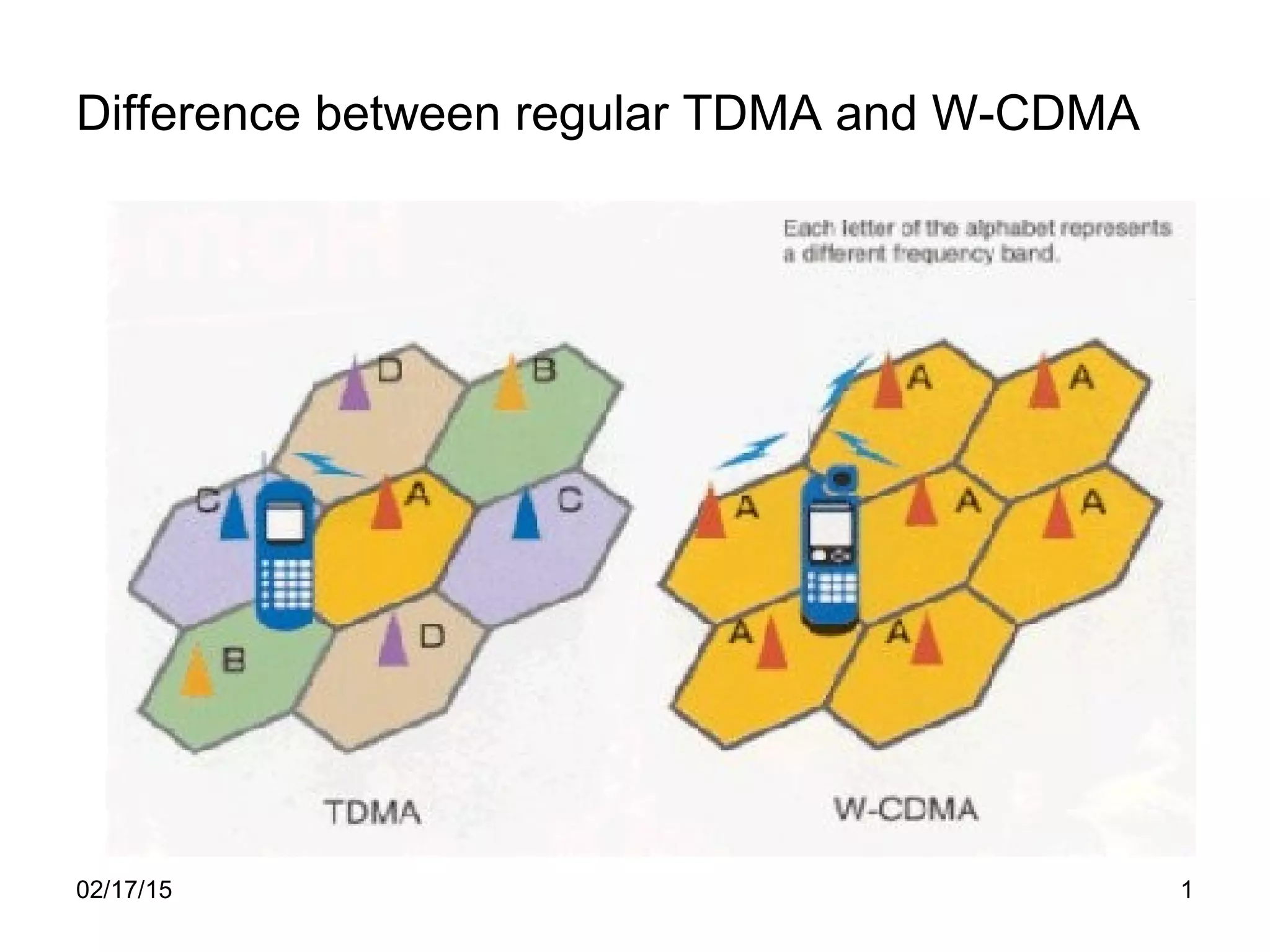
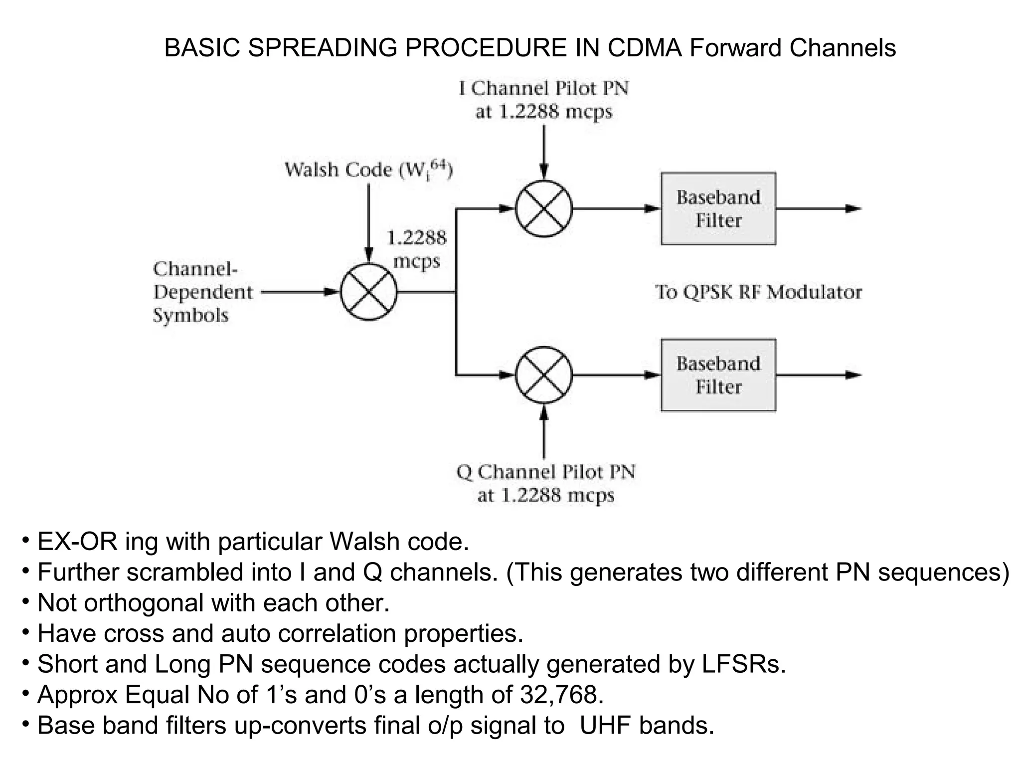
Difference between regular TDMA and W-CDMA
02/17/15 1
CDMA Channel Concept
Introduction to Walsh codes – Forward / Pilot / sync /
Paging / Traffic / power control / Reverse / ACCESS
Short and long PN codes - Spreading procedure
WALSH CODES
 Spread spectrum encoding techniques provides numerous radio channels
occupy in same frequency spectrum.
 For this orthogonal Walsh coding (enabling same frequency channels) is used.
 Even for precise system timing, control and over-head operation.
 They are 64-bit codes and their usage in IS-95 system
 64 0’s and 64 1’s. orthogonal to each other. Usually 8-bit signal is created.
 W0
64
– have equal No of 1’s and 0’s.
 Walsh encoded signal will appear as broad-band noise CDMA Rx all exist in
a same frequency spectrum.
 cdma –one and cdma-2000 systems based on uses CDMA technology to Provide over limited
amount of radio frequency spectrum.
 No of radio channels developed by spread spectrum techniques occupy the Same frequency
spectrum.
Spread-spectrum techniques are methods by which a signal (e.g. an electrical, electromagnetic,
or acoustic signal ) generated in a particular bandwidth is deliberately spread in the
frequency domain, resulting in a signal with a wider bandwidth. These techniques are used for a
variety of reasons, including the establishment of secure communications, increasing resistance
to natural interference and jamming, to prevent detection, and to limit power flux density (e.g. in
satellite downlinks).
 To enable distinct but same frequency channels, orthogonal Walsh spreading
Codes are used for channel coding.
 In IS-95 CDMA systems, Walsh code is used ( 64 bit codes).
 In ends, all are having equal 0’s and 1’s.
 They are orthogonal to each other. Two types of PN sequences are used.
They are Long PN code and short PN code.
Long PN CODE – data scrambling on forward traffic channels. Reverse traffic
channels can be distinguished.
cdmaOne Cells
144 kbps packet data
1.25 MHz channel
Moving to:
2 Mbps on 10MHz
TIMING OFFSET REUSE PATTERN
15
15
 The offset with BS used in CDMA
S/M must be all time synchronized
On the down link radio channels.
 The precise timing synchronization
Is achieved through the use of
The GPS.
BASIC SPREADING PROCEDURE IN CDMA Forward Channels
• EX-OR ing with particular Walsh code.
• Further scrambled into I and Q channels. (This generates two different PN sequences)
• Not orthogonal with each other.
• Have cross and auto correlation properties.
• Short and Long PN sequence codes actually generated by LFSRs.
• Approx Equal No of 1’s and 0’s a length of 32,768.
• Base band filters up-converts final o/p signal to UHF bands.
Forward logical channels Pilot channel
i=0
I channel
Q-channel
• Provides a reference signal for all the SDs within a cell.
• The all 0s walsh codes ( W0
64
) used for initial signal spreading on sequence of all 0’s.
• The I and Q signals drive QPSK modulalator.
• Resulting signal is un-modulated spread spectrum signal.
• Short PN sequence is used to identify the Base station
• 4-6 dB stronger than any other channel ( transmitted power)
Block interleaving
• To combat the effects of bit errors introduced during transmission of frame.
• Error control code used by the s/m may be able to correct 1 bit error out of 8 bit block.
• errors may spread out over other blocks.
Synchronization channel
• Initial time synchronization.
• Here Walsh code W32
64
( 32 0’s and 32 1’s) is used to spread the synchronization
channel signal.
• Even Synchronization channel message is also uses (32 0’s and 32 1’s).
• Short PN sequence is with offset and is used for further spreading.
• The synchronization message is about 1200 bps.
• The sync message undergoing convolution encoding, symbol repetition and
Block inter-leaving by raising the rate to 4.6 kbps.
• Sync message includes system and Network identification codes, paging channel
data rates, offset values short PN spreading rate. ( Fixed o/p power)
Sync Msg
1200 bps
2400
4800 bps
(No Long PN part)
W32
64
Paging channel
•Same function as paging channel in GSM.
• Used to page the SDs when there is a mobile-terminated call and sends control
messages to the SDs.
• This is mainly used for call set-up.
• In IS-95, there are as many as 7 paging channels is in operation at one time.
• WI
64
to W7
64
are used for this purpose.
• Additional Scrambling operation using long PN sequence.
• Generated by 42 bit LFSR (Linear Feedback Shift Register) yielding repeating
sequences (2 42
).
Traffic / power control channels ( 14.4 kbps)
• Traffic channels carry actual informaton ( Digitally encoded voice or data)
• Different rate sets – Rate set 1 – 9.6 kbps (max) to 4.8,2.4,1.2 kbps.
• RS2- 14.4, 7.2, 3.6 , 1.8 kbps.
• Symbol repetition block – Data rate is doubled.
• The “ puncture” function block selects 4 out of 6 bits offered and reduces the
data rates to 19.2 kbps ( actually from repetition – 14.4 X 2= 28.8 kbps)
• Then block interleaver prevents errors spreading.
• Further scrambling with long and short PN sequences before transmission.
• Power control information is used to set the output power of the mobile
on the reverse link and is multiplexed with the scrambled voice bits at a rate
of 800 bps.
Traffic / power control channels ( 9.6 kbps)
•No puncture Block
•After symbol repetition the data rates – 19.2 kbps.
Reverse Logical Channel
• Exists between SDs and the CDMA base station
• Encoding Digital information on reverse channel. ( Initially not spread to Walsh
codes)
• The data to be transmitted mapped to Walsh codes then transmitted.
• Every 6 bits are mapped to particular Walsh code.
• The system error rate is reduced in the process.
• The long PN sequence spread is derived from Subscriber’s 32 bit ESN number.
• User is uniquely identified within the CDMA System.
• The mapping of groups of 6 bits of data bits into walsh code is very
straightforward
since there exists a one-to-one relationship between the two.
There are basically two types of Reverse CDMA channels
1. Access channels.
2. Reverse traffic / control channels.
Reverse logical channels
Access channels
• Access channels processing for IS-95 CDMA System.
• Access message raises the data up to 28.8 kbps.
• The orthogonal modulation sub-system processes the signal by encoding every 6
Bits into 64 bits Walsh codes.
• The data rates increases upto 307.2 kcps.
• cps – standard notation within CDMA industry when referring signal spreading process.
• Long PN sequence spreads signal by a factor 4 that yields a chip rate of 1.2888 mcps.
• The form of modulation is UHF pass band signal slightly different than for forward
channels. (OQPSK is used instead of straightforward QPSK).
• A delay block of ½ of PN chip (406.9 ns) used in the Q path to implement OQSK
Traffic/power control channels
• Supports both voice and data at the two rate sets (RS1 and RS2)
• In both cases, the data rate at the input to the orthogonal modulator subsystem will
be 28.8 kbps.
• output process rate will be 307.2 kcps.
• The signal is processed by data burst randomizer that in essence to eliminate
redundant data.
• The signal is then spread by long PN sequence code and further scrambled by
short PN sequence.
CDMA frame format
Rate Set 2 (14.4 kbps)
267 information bits, 12 CRC bits
and 9 Tail bits
• same as GSM 20 ms duration.
• varying Number of information bits.
• 16 forward traffic channels ( 1.25 ms power control groups randomly inserted )
• Power control signal is 800 bps.
• CDMA forward synchronization (Sync) channel provides system configuration and
Timing information.
• Sync channel frames of 32 bits each. ( One SOM (Start of Message) bit
and 31 data bits-set to 1 in the First frame and 0 in subsequent frames of the same
message. Also SCI- Synchronized capsule Indicator)
• The paging channel is formatted 80 ms ( Four frames 20 X 4 )
• paging slots of 8 half frames of 10ms duration.
• Paging channel structure is also formatted into paging slot cycles, provides increased
battery life.
• Length of the paging channel – Min of 16 slots (1.28 s) to 2048 slots.
• MSs ESN will determines correct slots
Reverse channel frame formats
• Burst transmission
• Logically traffic channel channel is also divided into 20-ms traffic channel frames.
• Used by MS to communicate with the BS.
• Short message exchanges, call origination requests, responds to commands from BS
CDMA System (Layer 3) Operations
–Initialization/registration
• Frequency re-use factor is N=1.
• Ability to perform in short hand-offs.
• MS always operates with low battery power.
• MS initialization is for attached / Detached state.
• Requirements are given in state diagram.
CDMA MS call processing states
• Power up state – turn ON. Then acquiring pilot and sync channels.
• The three states are – idle state , system access state or traffic channel state.
SYSTEM ACCESS FLOW CHART
Priority Access and Channel Assignment
CDMA MS control on the traffic channel flow chart
DIFFERENT TYPES OF REGISTRATION
1. POWER –UP – Different band classes or PCS frequency blocks in alternative
operating modes, or analog and CDMA operations.
2. POWER-DOWN – registers and powers off with previously serving station.
3. Timer Based- various timers expires. The process forces the MS to register at
regular intervals.
4. Distance- based :- Distance between current serving BS and Base station where
it last registered exceeds certain threshold. MS calculates this
distance by using the latitude and longitude values for the BSs.
5. Zone Based :- MS registers when it enters into new Zone. First five modes are
called as autonomous registration and enabled by roaming status.
6. Parameter-change : considers some specific parameters stored in memory of MS
when enters to new zone.
7. Ordered :- Issue of ordered message ( requested by the BS)
8. Implicit :- page response message and origination message.
9. Traffic channel – BS registration message for a MS assigned to traffic channel.
10. User Zone – MS selects active user zone.
Call establishment
1.Initialization state- MS searches pilot channel by aligning its short its
short PN sequence with short PN code received. Valid sync code
initialize MS. W32
64
Walsh switching is done.
2. Idle state – MS is waiting to receive calls or data messages or
ready to originate calls. Support for subscriber connectivity and
Mobility. Continually monitoring radio channel quality. Getting all
access parameters, it goes to SLEEP mode to conserve MS battery
Power.
3. Access state – The CDMA mobile will enter the access state when
It receives a mobile directed message requiring an acknowledgement.
It originates a call or required to perform registration. Ms will randomly
attempt to access the system. MS receives a response from the BS
on the paging channel. Collision
Avoidance is necessary for successful system access.
Access channel probing
• Transmission of a series of access probe sequences is known as an access attempt.
• Each access probe consists of an access channel preamble ( 1-16 frames of 0’s).
• Three to 10 frames ( Access channel message capsule)
• This yields 4-26 number of 20 ms frames.
• Two types of access messages – 1. Response message 2. Request message
• MS sending a series
Of sequences of
Access probes of
Increasing power
Levels.
• Repeated transmission
• Ack over paging channel.
• For MSs access attempt
Is un-successful, then
Further additional
Attempts with probe
Sequences is tried out.
Traffic state
• Call origination.
• Information – Either voice or Data.
• MS transmits voice and signaling information on the FTC.
• Blank –end-burst – signaling replaces 1.25 ms of speech data with signaling
message bursts.
dim-end-burst – inserts signaling messages when speech activity is low.
Mobile-originated call
• If the access is successful, then
FTC corresponds to particular
Walsh code.
• Preamble information sent by MS.
• Paging channel information is sent
By MS.
Mobile-terminated call
• BS sends a message to the MS on the paging
Channel.
• If it attached to the system, MS sends ACK
On access channel.
• MS configures itself.
Call handoff
Idle handoff
• Hand-off can occur in 1. IDLE 2. ACCESS 3. TRAFFIC cases
• Depends on MSs present state.
• MS is reporting RSS.
• Advantage of CDMA – Supporting both voice and high speed data
• Signal strength of a cell or sector is considered.
• stronger PgC with RSS measurements.
Access handoff
• Access hand-off occurs, before the MS begins sending access probes.
• Probe ACK is also receieved
Soft handoff
Soft, softer, and soft-softer
handoff
a. Soft hand-off – MS able to communicate with several sectors
of the current cells simultaneously. ( over FTC)
b. Soft hand – off - MS with only 2 sectors of a same cell.
c. Soft-softer -
Hard handoff
• Inter-carrier hand-off causes radio link to be abruptly interrupted for a short
Period while the base and MS switch from one carrier freq to another.
There are two basic types of inter-carrier handoffs
1. Hand-down – hard hand over due to two different carriers within a same cell.
2. Hard hand-off - hard hand over due to two different carriers within a different cells
Due to inter-carrier handoff
Due to disjointed regions
Border and transition cells

Cdma

  • 1.
    Difference between regularTDMA and W-CDMA 02/17/15 1
  • 2.
    CDMA Channel Concept Introductionto Walsh codes – Forward / Pilot / sync / Paging / Traffic / power control / Reverse / ACCESS Short and long PN codes - Spreading procedure
  • 3.
    WALSH CODES  Spreadspectrum encoding techniques provides numerous radio channels occupy in same frequency spectrum.  For this orthogonal Walsh coding (enabling same frequency channels) is used.  Even for precise system timing, control and over-head operation.  They are 64-bit codes and their usage in IS-95 system  64 0’s and 64 1’s. orthogonal to each other. Usually 8-bit signal is created.  W0 64 – have equal No of 1’s and 0’s.  Walsh encoded signal will appear as broad-band noise CDMA Rx all exist in a same frequency spectrum.
  • 4.
     cdma –oneand cdma-2000 systems based on uses CDMA technology to Provide over limited amount of radio frequency spectrum.  No of radio channels developed by spread spectrum techniques occupy the Same frequency spectrum. Spread-spectrum techniques are methods by which a signal (e.g. an electrical, electromagnetic, or acoustic signal ) generated in a particular bandwidth is deliberately spread in the frequency domain, resulting in a signal with a wider bandwidth. These techniques are used for a variety of reasons, including the establishment of secure communications, increasing resistance to natural interference and jamming, to prevent detection, and to limit power flux density (e.g. in satellite downlinks).  To enable distinct but same frequency channels, orthogonal Walsh spreading Codes are used for channel coding.  In IS-95 CDMA systems, Walsh code is used ( 64 bit codes).  In ends, all are having equal 0’s and 1’s.  They are orthogonal to each other. Two types of PN sequences are used. They are Long PN code and short PN code. Long PN CODE – data scrambling on forward traffic channels. Reverse traffic channels can be distinguished.
  • 7.
    cdmaOne Cells 144 kbpspacket data 1.25 MHz channel Moving to: 2 Mbps on 10MHz TIMING OFFSET REUSE PATTERN 15 15  The offset with BS used in CDMA S/M must be all time synchronized On the down link radio channels.  The precise timing synchronization Is achieved through the use of The GPS.
  • 8.
    BASIC SPREADING PROCEDUREIN CDMA Forward Channels • EX-OR ing with particular Walsh code. • Further scrambled into I and Q channels. (This generates two different PN sequences) • Not orthogonal with each other. • Have cross and auto correlation properties. • Short and Long PN sequence codes actually generated by LFSRs. • Approx Equal No of 1’s and 0’s a length of 32,768. • Base band filters up-converts final o/p signal to UHF bands.
  • 9.
    Forward logical channelsPilot channel i=0 I channel Q-channel • Provides a reference signal for all the SDs within a cell. • The all 0s walsh codes ( W0 64 ) used for initial signal spreading on sequence of all 0’s. • The I and Q signals drive QPSK modulalator. • Resulting signal is un-modulated spread spectrum signal. • Short PN sequence is used to identify the Base station • 4-6 dB stronger than any other channel ( transmitted power)
  • 10.
    Block interleaving • Tocombat the effects of bit errors introduced during transmission of frame. • Error control code used by the s/m may be able to correct 1 bit error out of 8 bit block. • errors may spread out over other blocks.
  • 11.
    Synchronization channel • Initialtime synchronization. • Here Walsh code W32 64 ( 32 0’s and 32 1’s) is used to spread the synchronization channel signal. • Even Synchronization channel message is also uses (32 0’s and 32 1’s). • Short PN sequence is with offset and is used for further spreading. • The synchronization message is about 1200 bps. • The sync message undergoing convolution encoding, symbol repetition and Block inter-leaving by raising the rate to 4.6 kbps. • Sync message includes system and Network identification codes, paging channel data rates, offset values short PN spreading rate. ( Fixed o/p power) Sync Msg 1200 bps 2400 4800 bps (No Long PN part) W32 64
  • 12.
    Paging channel •Same functionas paging channel in GSM. • Used to page the SDs when there is a mobile-terminated call and sends control messages to the SDs. • This is mainly used for call set-up. • In IS-95, there are as many as 7 paging channels is in operation at one time. • WI 64 to W7 64 are used for this purpose. • Additional Scrambling operation using long PN sequence. • Generated by 42 bit LFSR (Linear Feedback Shift Register) yielding repeating sequences (2 42 ).
  • 13.
    Traffic / powercontrol channels ( 14.4 kbps) • Traffic channels carry actual informaton ( Digitally encoded voice or data) • Different rate sets – Rate set 1 – 9.6 kbps (max) to 4.8,2.4,1.2 kbps. • RS2- 14.4, 7.2, 3.6 , 1.8 kbps. • Symbol repetition block – Data rate is doubled. • The “ puncture” function block selects 4 out of 6 bits offered and reduces the data rates to 19.2 kbps ( actually from repetition – 14.4 X 2= 28.8 kbps) • Then block interleaver prevents errors spreading. • Further scrambling with long and short PN sequences before transmission. • Power control information is used to set the output power of the mobile on the reverse link and is multiplexed with the scrambled voice bits at a rate of 800 bps.
  • 14.
    Traffic / powercontrol channels ( 9.6 kbps) •No puncture Block •After symbol repetition the data rates – 19.2 kbps.
  • 15.
    Reverse Logical Channel •Exists between SDs and the CDMA base station • Encoding Digital information on reverse channel. ( Initially not spread to Walsh codes) • The data to be transmitted mapped to Walsh codes then transmitted. • Every 6 bits are mapped to particular Walsh code. • The system error rate is reduced in the process. • The long PN sequence spread is derived from Subscriber’s 32 bit ESN number. • User is uniquely identified within the CDMA System. • The mapping of groups of 6 bits of data bits into walsh code is very straightforward since there exists a one-to-one relationship between the two. There are basically two types of Reverse CDMA channels 1. Access channels. 2. Reverse traffic / control channels.
  • 16.
    Reverse logical channels Accesschannels • Access channels processing for IS-95 CDMA System. • Access message raises the data up to 28.8 kbps. • The orthogonal modulation sub-system processes the signal by encoding every 6 Bits into 64 bits Walsh codes. • The data rates increases upto 307.2 kcps. • cps – standard notation within CDMA industry when referring signal spreading process. • Long PN sequence spreads signal by a factor 4 that yields a chip rate of 1.2888 mcps. • The form of modulation is UHF pass band signal slightly different than for forward channels. (OQPSK is used instead of straightforward QPSK). • A delay block of ½ of PN chip (406.9 ns) used in the Q path to implement OQSK
  • 17.
    Traffic/power control channels •Supports both voice and data at the two rate sets (RS1 and RS2) • In both cases, the data rate at the input to the orthogonal modulator subsystem will be 28.8 kbps. • output process rate will be 307.2 kcps. • The signal is processed by data burst randomizer that in essence to eliminate redundant data. • The signal is then spread by long PN sequence code and further scrambled by short PN sequence.
  • 18.
    CDMA frame format RateSet 2 (14.4 kbps) 267 information bits, 12 CRC bits and 9 Tail bits • same as GSM 20 ms duration. • varying Number of information bits. • 16 forward traffic channels ( 1.25 ms power control groups randomly inserted ) • Power control signal is 800 bps. • CDMA forward synchronization (Sync) channel provides system configuration and Timing information. • Sync channel frames of 32 bits each. ( One SOM (Start of Message) bit and 31 data bits-set to 1 in the First frame and 0 in subsequent frames of the same message. Also SCI- Synchronized capsule Indicator) • The paging channel is formatted 80 ms ( Four frames 20 X 4 ) • paging slots of 8 half frames of 10ms duration. • Paging channel structure is also formatted into paging slot cycles, provides increased battery life. • Length of the paging channel – Min of 16 slots (1.28 s) to 2048 slots. • MSs ESN will determines correct slots
  • 20.
    Reverse channel frameformats • Burst transmission • Logically traffic channel channel is also divided into 20-ms traffic channel frames. • Used by MS to communicate with the BS. • Short message exchanges, call origination requests, responds to commands from BS
  • 21.
    CDMA System (Layer3) Operations –Initialization/registration • Frequency re-use factor is N=1. • Ability to perform in short hand-offs. • MS always operates with low battery power. • MS initialization is for attached / Detached state. • Requirements are given in state diagram.
  • 22.
    CDMA MS callprocessing states • Power up state – turn ON. Then acquiring pilot and sync channels. • The three states are – idle state , system access state or traffic channel state.
  • 23.
    SYSTEM ACCESS FLOWCHART Priority Access and Channel Assignment
  • 24.
    CDMA MS controlon the traffic channel flow chart
  • 25.
    DIFFERENT TYPES OFREGISTRATION 1. POWER –UP – Different band classes or PCS frequency blocks in alternative operating modes, or analog and CDMA operations. 2. POWER-DOWN – registers and powers off with previously serving station. 3. Timer Based- various timers expires. The process forces the MS to register at regular intervals. 4. Distance- based :- Distance between current serving BS and Base station where it last registered exceeds certain threshold. MS calculates this distance by using the latitude and longitude values for the BSs. 5. Zone Based :- MS registers when it enters into new Zone. First five modes are called as autonomous registration and enabled by roaming status. 6. Parameter-change : considers some specific parameters stored in memory of MS when enters to new zone. 7. Ordered :- Issue of ordered message ( requested by the BS) 8. Implicit :- page response message and origination message.
  • 26.
    9. Traffic channel– BS registration message for a MS assigned to traffic channel. 10. User Zone – MS selects active user zone. Call establishment 1.Initialization state- MS searches pilot channel by aligning its short its short PN sequence with short PN code received. Valid sync code initialize MS. W32 64 Walsh switching is done. 2. Idle state – MS is waiting to receive calls or data messages or ready to originate calls. Support for subscriber connectivity and Mobility. Continually monitoring radio channel quality. Getting all access parameters, it goes to SLEEP mode to conserve MS battery Power. 3. Access state – The CDMA mobile will enter the access state when It receives a mobile directed message requiring an acknowledgement. It originates a call or required to perform registration. Ms will randomly attempt to access the system. MS receives a response from the BS on the paging channel. Collision Avoidance is necessary for successful system access.
  • 27.
    Access channel probing •Transmission of a series of access probe sequences is known as an access attempt. • Each access probe consists of an access channel preamble ( 1-16 frames of 0’s). • Three to 10 frames ( Access channel message capsule) • This yields 4-26 number of 20 ms frames. • Two types of access messages – 1. Response message 2. Request message • MS sending a series Of sequences of Access probes of Increasing power Levels. • Repeated transmission • Ack over paging channel. • For MSs access attempt Is un-successful, then Further additional Attempts with probe Sequences is tried out.
  • 28.
    Traffic state • Callorigination. • Information – Either voice or Data. • MS transmits voice and signaling information on the FTC. • Blank –end-burst – signaling replaces 1.25 ms of speech data with signaling message bursts. dim-end-burst – inserts signaling messages when speech activity is low. Mobile-originated call • If the access is successful, then FTC corresponds to particular Walsh code. • Preamble information sent by MS. • Paging channel information is sent By MS.
  • 29.
    Mobile-terminated call • BSsends a message to the MS on the paging Channel. • If it attached to the system, MS sends ACK On access channel. • MS configures itself.
  • 30.
    Call handoff Idle handoff •Hand-off can occur in 1. IDLE 2. ACCESS 3. TRAFFIC cases • Depends on MSs present state. • MS is reporting RSS. • Advantage of CDMA – Supporting both voice and high speed data • Signal strength of a cell or sector is considered. • stronger PgC with RSS measurements. Access handoff • Access hand-off occurs, before the MS begins sending access probes. • Probe ACK is also receieved
  • 31.
    Soft handoff Soft, softer,and soft-softer handoff a. Soft hand-off – MS able to communicate with several sectors of the current cells simultaneously. ( over FTC) b. Soft hand – off - MS with only 2 sectors of a same cell. c. Soft-softer -
  • 32.
    Hard handoff • Inter-carrierhand-off causes radio link to be abruptly interrupted for a short Period while the base and MS switch from one carrier freq to another. There are two basic types of inter-carrier handoffs 1. Hand-down – hard hand over due to two different carriers within a same cell. 2. Hard hand-off - hard hand over due to two different carriers within a different cells Due to inter-carrier handoff
  • 33.
    Due to disjointedregions Border and transition cells