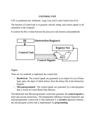
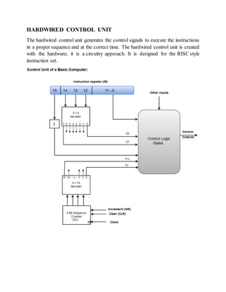
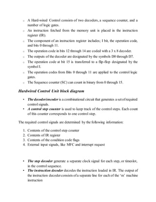
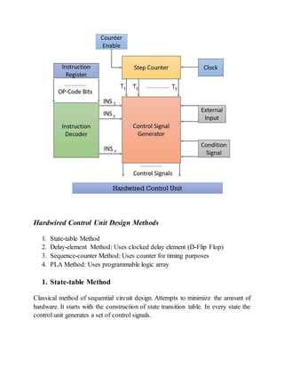
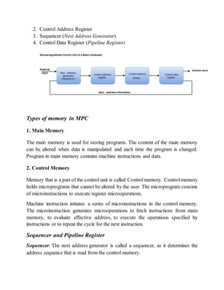
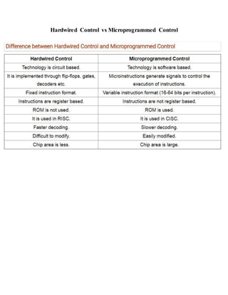
The document discusses control units in CPUs. There are two main methods for implementing control units: hardwired and microprogrammed. A hardwired control unit generates control signals through circuitry using logic gates, while a microprogrammed control unit generates control signals by executing a stored microprogram. Overall, hardwired control units are faster but less flexible, while microprogrammed control units are slower but more flexible and modifiable.
CCS335 _ Neural Networks and Deep Learning Laboratory_Lab Complete Record
Generate Control Signals CPU
1. CONTROL UNIT
CPU is partitioned into Arithmetic Logic Unit (ALU) and Control Unit (CU).
The function of control unit is to generate relevant timing and control signals to all
operations in the computer.
It controls the flow of data between the processor and memory and peripherals
Types:
There are two methods to implement the control unit:
• Hardwired: The control signals are generated as an output of a set of basic
logic gates, the input of which derives from the binary bits in the Instruction
Register.
• Microprogrammed: The control signals are generated by a microprogram
that is stored in Control Read Only Memory.
The Hardwired and Microprogrammed controlunit generates the control signals to
fetch and execute instructions. The fundamental difference between hardwired and
microprogrammed control unit is that hardwired is a circuitry approach whereas,
the microprogram control unit is implemented by programming.
2. HARDWIRED CONTROL UNIT
The hardwired control unit generates the control signals to execute the instructions
in a proper sequence and at the correct time. The hardwired control unit is created
with the hardware; it is a circuitry approach. It is designed for the RISC style
instruction set.
3. o A Hard-wired Control consists of two decoders, a sequence counter, and a
number of logic gates.
o An instruction fetched from the memory unit is placed in the instruction
register (IR).
o The component of an instruction register includes; I bit, the operation code,
and bits 0 through 11.
o The operation code in bits 12 through 14 are coded with a 3 x 8 decoder.
o The outputs of the decoder are designated by the symbols D0 through D7.
o The operation code at bit 15 is transferred to a flip-flop designated by the
symbol I.
o The operation codes from Bits 0 through 11 are applied to the control logic
gates.
o The Sequence counter (SC) can count in binary from 0 through 15.
Hardwired Control Unit block diagram
• The decoder/encoder is a combinational circuit that generates a setofrequired
control signals.
• A control step counter is used to keep track of the control steps. Each count
of this counter corresponds to one control step.
The required control signals are determined by the following information:
1. Contents of the control step counter
2. Contents of IR register
3. Contents of the condition code flags
4. External input signals, like MFC and interrupt request
• The step decoder generate a separate clock signal for each step, or timeslot,
in the control sequence.
• The instruction decoder decodes the instruction loaded in IR. The output of
the instruction decoderconsists ofa separate line for each of the ‘m’ machine
instruction
4. Hardwired Control Unit Design Methods
1. State-table Method
2. Delay-element Method: Uses clocked delay element (D-Flip Flop)
3. Sequence-counter Method: Uses counter for timing purposes
4. PLA Method: Uses programmable logic array
1. State-table Method
Classical method of sequential circuit design. Attempts to minimize the amount of
hardware. It starts with the construction of state transition table. In every state the
control unit generates a set of control signals.
5. 2. Delay-element Method
Control signals or groups of control signals are activated in propersequence. There
is a specific time delay between activation of two consecutive control signals or
groups of control signal.
For synchronous operation, delay elements are implemented using D flip-flops and
controlled by common clock signal.
Rules for Delay-elementMethod
• Each sequence of two successive micro-operations requires a delay element.
• The signals that are intended to activate same control lines are logically
ORed to get one common output signals
Advantages of Hardwired Control Unit
1. Fast because control signals are generated by combinational circuits.
2. The delay in generation of control signals depends upon the number of gates
Disadvantages
1. More the control signals required by CPU, more complex will be the design
of control unit.
6. 2. No Flexibility. Modification in control signal is very difficult i.e. it requires
rearranging of wires in the hardware circuit.
3. Difficult to add new feature in existing design of control unit
Micro-Programmed Control Unit
A micro-programmed control unit is implemented using programming approach. A
sequence of microoperations are carried out by executing a program consisting of
micro-instructions.
Micro-program, consisting of micro-instructions is stored in the control memory of
the control unit.
Execution of a micro-instruction is responsible for generation of a set of control
signals.
Important Terms
• Control Word: - The control variables at any time are represented by 1’s and
0’s, known as Control Word. Control words can be programmed to perform
various operations.
• Micro-Operations: The operations performed on the data stored inside the
registers are called micro-operations.
• Micro-Programs: Microprogramming is the concept for generating control
signals using programs. These programs are called micro-programs.
• Micro-Instructions: The instructions that make micro-program are called
micro-instructions.
• Micro-Code: Micro-program is a group of microinstructions. The micro-
program can also be termed as micro-code.
• Control Memory: Micro-programs are stored in the read only memory
(ROM). That memory is called control memory.
Micro-Programmed control Organization
1. Control Memory
7. 2. Control Address Register
3. Sequencer (Next Address Generator)
4. Control Data Register (Pipeline Register)
Types of memory in MPC
1. Main Memory
The main memory is used for storing programs. The content of the main memory
can be altered when data is manipulated and each time the program is changed.
Program in main memory contains machine instructions and data.
2. Control Memory
Memory that is a part of the control unit is called Controlmemory. Controlmemory
holds microprograms that cannot be altered by the user. The microprogram consists
of microinstructions to execute register microoperations.
Machine instruction initiates a series of microinstructions in the control memory.
The microinstruction generates microoperations to fetch instructions from main
memory, to evaluate effective address, to execute the operations specified by
instructions or to repeat the cycle for the next instruction.
Sequencer and Pipeline Register
Sequencer: The next address generator is called a sequencer, as it determines the
address sequence that is read from the control memory.
8. Functions:
1. Incrementing the control register
2. Loading an address from control memory to CAR.
3. Loading an initial address
PipelineRegister: Thecontroldata register holds the present microinstruction while
the next address is computed and read from the memory. This data register is called
pipeline register.
Selection of address for Control Memory
Address Sequencing
Address Sequencing = Sequencer: Next Address Generator. Selection of address for
control memory
Routine: Microinstruction are stored in control memory in groups
Mapping
Instruction Code Address in control memory (where routine is located)
Address Sequencing Capabilities: control memory address
1. Incrementing of the control address register
2. Unconditional branch or conditional branch, depending on status bit
conditions
3. Mapping process (bits of the instruction address for control memory )
4. A facility for subroutine return
9. Multiplexer
1. CAR Increment
2. JMP/CALL
3. Mapping
4. Subroutine Return
Control Address Register CAR: CAR receive the address from 4 different
paths:
1. Incrementer
2. Branch address from control memory
Instruction code
Mapping
Logic
Multiplexers
Control memory (ROM)
Subroutine
Register
(SBR)
Branch
Logic
Status
Bits
Microoperations
Control Address Register
(CAR)
Incrementer
MUX
Select
Select a status
Bit
Branch address
10. 3. Mapping Logic
4. SBR Subroutine Register
SBR Subroutine Register: Return Address cannot be stored in ROM. Return
Address for a subroutine is stored in SBR
Conditional Branching
• Status Bits: Controlthe conditional branch decisions generated in the Branch
Logic
• Branch Logic: Test the specified condition and Branch to the indicated
address if the condition is met; otherwise, the control address register is just
incremented.
Mapping of Instruction
Mapping: transformation from instruction code bits to microinstruction address in
control memory where routine is located.
Each computer instruction has its own microprogram
Routine stored in a given location of the control memory
11. 4 bit Opcode = specify up to 16 distinct instruction
Mapping Process: Converts the 4-bit Opcode to a 7-bit control memory address
1. Place a “0” in the most significant bit of the address
2. Transfer 4-bit Operation code bits
3. Clear the two least significant bits of the CAR
Subroutine
Subroutines are programs that are used by other routines. Subroutine can be called
from any point within the main body of the microprogram
Subroutine must have a provision for:
• Storing the return address during a subroutine call
• Restoring the address during a subroutine return (Last-In First Out(LIFO)
Register Stack)
Micro-instruction Types
• Vertical Micro-Programming : Each micro-instruction specifies single (or
few) micro-operations to be performed
• Horizontal Micro-Programming : Each micro-instruction specifies many
different micro-operations to be performed in parallel
Vertical Micro-programming
• Width is narrow
• n control signals encoded into log2 n bits
• Limited ability to express parallelism
• Considerable encoding ofcontrolinformation requires external memory word
decoder to identify the exact control line being manipulated
13. Advantages of Micoprogrammed Control Unit
1. The design of micro-program control unit is less complex because micro-
programs are implemented using software routines.
2. The micro-programmed control unit is more flexible because design
modifications, correction and enhancement is easily possible.
3. The new or modified instruction set of CPU can be easily implemented by
simply rewriting or modifying the contents of control memory.
4. The fault can be easily diagnosed in the micro-program control unit using
diagnostics tools by maintaining the contents of flags, registers and counters
Disadvantages:
1. The micro-program control unit is slower than hardwired control unit. That
means to execute an instruction in micro-program control unit requires more
time.
2. The micro-program control unit is expensive than hardwired control unit in
case of limited hardware resources.
3. The design duration of micro-program control unit is more than hardwired
control unit for smaller CPU.