SlideShare a Scribd company logo
1 of 11
Download to read offline
www.westernautomation.com1
Ground Fault Circuit Interrupters (GFCIs) for AC & DC Systems
This article has been written mainly with North American users in mind, and is intended to provide readers with practical informa-
tion on the operation and selection of GFCIs. We would welcome responses to the article, favorable or otherwise, so that we can
learn from our readers.
The international version of this article is entitled Demystifying RCDs and can be seen at www.rcd.ie.
See sister articles: Leakage Current Detection for AC & DC Application.
Starting With Some Acronyms
UL: Underwriters Laboratory
CSA: Canadian Standards Association
IEC: International Electrotechnical Commission
GFCI: Ground Fault Circuit Interrupter
RCD: Residual Current Device (IEC term for GFCI)
GFCI Product Standards
The most relevant standard for GFCIs in the USA is UL943.
For Canada it is CSA C22.2
For Mexico it is NMX-J-520.
Although the numbering is different in each case, the three countries share the same basic GFCI requirements.
A GFCI (ground fault circuit interrupter) is intended to provide protection against electric shock. It does this by opening one or
more contacts to disconnect power from a circuit or load when the ground fault current flowing in the circuit protected by the
GFCI reaches the rated operating current of the GFCI.
Figure 1 – 120V system
www.westernautomation.com2
GFCIs for AC & DC Systems
Figure 1 shows a typical 120V single phase configuration. Under normal conditions the current IL flowing from the supply to the
load will be equal to the current IN flowing back from the load. Because these currents are of equal magnitude but flowing in
opposite directions within the current transformer (CT), their vector sum will be zero and the CT will produce no output. If a person
touches a live part as demonstrated in Figure 1, an additional current Ig will flow through the person’s body to ground and return to
the supply via the ground or earth return path. The current IL will now be greater than IN by the value of Ig and the CT will produce
a resultant output in response to this differential or residual current. This output will be sensed by the electronic circuit, and if it is
above a predetermined level (typically 6mA) it will cause the GFCI contacts to open and disconnect the supply from the load and
thereby provide protection. The differential current level at which the GFCI is designed to operate is known as its rated ground
fault operating current, and can be designated as I�n, a term widely used in IEC documents.
Figure 2 shows a typical 240V two line arrangement. In this case the voltage across L1 and L2 is 240V and this supply is used to
supply high power loads, e.g. water heaters and cookers, etc. The centre of the supply transformer is connected to ground and
this centre point is distributed as a neutral conductor. The voltage between N and L1 or L2 will be 120V, and this supply is used to
power smaller loads, e.g. receptacle outlets and lighting circuits, etc. In this arrangement, all three current carrying conductors are
passed through the CT. Under normal conditions the vector sum of all currents flowing through the CT will be zero. However in the
event of a ground fault a differential current will flow back to the supply via earth, bypassing the CT. When this current exceeds the
operating threshold of the GFCI the supply to all loads will be disconnected. In some GFCIs, the neutral may also have a switchable
contact.
It is worth noting that in this system the maximum touch voltage is 120V even though the installation uses a 240V supply.
Figure 2 – 240V system
www.westernautomation.com3
In the case of GFCIs, a ground fault current therefore refers to any current other than the load current. The ground fault current
may flow through a person’s body or through a fault in equipment or wiring anywhere on the load side of the GFCI. The key factor in
the ability of the GFCI to detect a ground fault current and provide protection is the connection of the supply neutral conductor to
earth at the origin of the installation.
Although the load current will typically be in the amperes range, the differential current I�n will generally be in the milliamps range.
Typical maximum values of I�n in the USA are 6mA for personal shock protection, 30mA for equipment protection, and 300mA for
fire protection.
It is worth noting that the normal human body resistance for most people is in the range 1000 - 2000 Ohms, but for some people it
may be as low as 500 ohms, so for a touch voltage of 120V the current through the body will generally be in excess of 50mA.
6mA versus 30mA Operating Thresholds.
In the USA, the operating threshold for a GFCI for personal shock protection is 6mA. In most of the rest of the world, the threshold
is 30mA. There are two reasons for this difference. The first relates to safety, and the second relates to technology.
Tests on the human body have indicated that as the current is increased from zero mA, muscles tend to seize at about the 10mA
level with the result that a person touching a live conductor may not be able to let go a live conductor at currents above 10mA.
This is referred to as the “let-go” limit, and the North American GFCI standards decided to set the operating level of GFCIs at 6mA
so as to have a comfortable safety margin below this threshold. At about 40mA, heart fibrillation starts to occur, which could lead
to heart failure. European manufacturers decided to set 30mA as the operating level of RCDs (GFCIs) so as to have a comfortable
safety margin below this threshold. This begs the question as to why the Europeans would set a higher level than the let-go level.
The answer is Technology. North America uses electronic technology in their GFCIs, and it is relatively easy to set an operating
threshold of 6mA for such devices. However, most European devices use electromechanical technology, and it is extremely difficult
for such devices to operate at the 6mA level, so they chose 30mA because they can detect this level quite easily and it provides
protection against heart fibrillation. European manufacturers had a substantially greater influence on IEC standards and practice,
and the 30mA level has been adopted in most areas worldwide with the exception of North America.
(See IEC60479 for more detailed information on the effect of current on the body)
Double Grounded Neutral (DGN) Problem
Figure 1 showed a typical situation whereby the GFCI provides protection. However, a condition that could prevent the GFCI from
providing protection is represented in figure 3 below.
GFCIs for AC & DC Systems
Figure 3 – 120V system
www.westernautomation.com4
This condition could arise due to miswiring or insulation breakdown. The fault current Ig will flow through the body as before, but
will now split into two currents, Ige and Ign, with Ige flowing back to the supply via the earth or ground return path, and Ign re-
turning back to the supply via the DGN fault connection and the neutral conductor. The ratio or division of these two currents will
depend on the impedance of the neutral and ground paths. In many installations, the ground wire could be of smaller cross sectional
area than the neutral wire with the result that Ige will be smaller than Ign. In any event, the CT will no longer see the total fault
current and will only see Ige, and if Ige is less than the trip threshold of the GFCI, the device will not trip.
UL943 requires GFCI manufacturers to provide an effective solution to this problem in that the GFCI must trip automatically or
continue to provide protection under this condition. Figure 4 shows one example of how this can be achieved, but other mean are
also used in practice.
In the arrangement of figure 4, there is a second current transformer, CT2. Connected to this is an oscillator circuit which induces
a current into CT2 winding. In this example, the oscillator produces a continuous current Iosc into CT2 winding. Under normal con-
ditions, this current does nothing. However when the DGN fault occurs, a loop is formed by the neutral and earth paths, and Iosc is
induced into this loop. CT1 see Iosc as a fault current and trips the GFCI. The DGN detecting circuit can function without an earth
fault and without a load connected.
GFCIs for AC & DC Systems
Figure 4 – 120V system
www.westernautomation.com5
The DC system may be totally isolated from ground, or may have one side connected to ground. If one side is connected to ground
as shown by the dotted line, a person touching the +ve side of the supply will be exposed to a shock risk. In the case of a totally
isolated system, if one side becomes inadvertently grounded, e.g. because of a first fault, a person touching the opposite side of the
supply will be exposed to a shock risk. In either case, if a ground fault current above a certain level flows in the circuit, this will be
detected and cause automatic opening of the contacts.
It may seem strange to use a current transformer to detect a DC ground fault current. However this is achieved by driving the CT
core into and out of saturation at a certain frequency, and using the DC fault current to generate a detectable change in the satura-
tion characteristics.
DC Sensing GFCIs
DC ground fault currents can occur in installations powered from DC, such as
• Mines
• Tunnels
• Solar panels
• Electric vehicles
• Ships
• Aircraft, etc.
DC currents through the body can be every bit as dangerous as AC currents and GFCI protection should be provided where shock
risks exist. In IEC, GFCIs/RCDs that provide protection against both AC and DC ground fault currents are referred to as B Types.
Commercial: Western Automation (WA) can provide GFCI solutions in the form of technology or GCFI
products for use in AC & DC systems.
GFCIs for AC & DC Systems
Figure 5 – DC system
www.westernautomation.com6
Types of GFCIs
GFCI types can be categorised based on their construction, performance or configuration etc, as follows.
Mounting
• Panel Types – e.g. installed in panelboards
• Receptacle Types – a receptacle incorporating a GFCI
• Portable Types - fitted in a plug, an adaptor, or in a cord.
The panel type GFCI may be single phase or three phase whereas the receptacle and portable types are generally single phase
only. The panel types generally provide protection for part of or a complete installation. The receptacle and portable types provide
protection for loads connected directly to the device. For this reason they are sometimes referred to as “point of use” GFCIs.
Receptacle types provided with feed through terminals may also be used for protection of downstream receptacles. This is normal
practice in the USA.
Contacts
The GFCI figures shown in this document have two contacts in each case. However, in practice, single pole GFCIs tend to use a single
contact in the live pole, and an unswitched neutral pole. Portable GFCIs and receptacle based GFCIs break all poles.
AC or DC Sensing
GFCIs may also be categorised based on the type of ground fault current they can detect, e.g. detecting AC only, or detecting AC & DC
fault currents.
Trip Levels & Trip Times
GFCIs covered by UL943 are known as Class A devices because their specified trip level (I�n) is in the range 4 – 6mA.
The trip time specified in UL943 for GFCIs is derived from the following formula.
T = (20/I)1.43 Where T = time in seconds
I = ground fault current in milliamps
The GFCI trip threshold combined with its response time are the most critical factors in minimising the risk of heart fibrillation and
thereby providing protection of human life against the effects of electric shock. These two factors are addressed by the above formula.
It is not easy to figure out from the formula what the trip time should be for say, 6mA, 20mA or 50mA, so we have produced figure 5
below to show the relationship between fault current and trip time.
The graph provides a ready indication of
the maximum trip time in relation to a given
ground fault current. In practice, most GFCIs
operate in less than 100mS regardless of the
fault current level.
GFCIs for AC & DC Systems
Figure 6 - Maximum trip time in relation to a given ground fault current
www.westernautomation.com7
Method Of Latching
Latching is the means by which the contacts of the GFCI can be closed and held closed. GFCIs fall into the following two broad catego-
ries:
ML types that are Mechanically or Magnetically latching, and EL types that are Electrically latching.
The ML device contacts can be closed and will remain closed regardless of whether or not a supply is present. The ML device may
cease to operate in the event of loss of supply neutral. (see Problems with GFCIs)
The EL type requires the presence of a supply above a certain voltage to enable its contacts to be closed (manually or automatically),
and when the supply is reduced below a certain level the contacts open automatically.
EL types fall into two categories:
ELR and ELO types.
The ELR GFCI opens automatically on loss of supply but recloses automatically on restoration of the supply (electrically latching and
automatically reclosing when power is restored). It therefore provides protection against loss of supply neutral, but also recloses once
the supply is restored. The ELO GFCI opens automatically on loss of supply and remains open on restoration of the supply (electrically
latching and remaining open).The ELO also provides protection against loss of supply neutral. However, the ELO response is generally
used in portable type GFCIs, and is not considered suitable for applications where power needs to be restored to equipment such as
refrigerators, etc.
Testing(see Problems with GFCIs)
GFCIs are fitted with a test button to enable users to test the GFCI from time to time. In fact it is recommended that the GFCI be test-
ed on a regular basis because if a GFCI fails for any reason, the user will not be aware of the failure unless the test button is operated.
(see: Reliability – Design Factors)
Selecting GFCIs
Factors such as the rated voltage, load current, residual current and number of poles should be fairly obvious, so I will deal with some
other factors.
1. AC, Rectified AC and DC
In order to choose a GFCI the user or installer should first of all decide on the type of protection required. As an absolute minimum
requirement, all GFCIs will provide protection against AC ground fault currents. However, if any type of power control is used on
the load, e.g. speed control for electric drills, heat control for hair dryers or heaters, dimmer control for lighting, partial or complete
rectification of the AC supply will be used within the equipment, and this could result in a ground fault current that is not pure AC, but
rectified AC. Figure 6 shows examples of typical wave shapes produced by power controlled equipment.
GFCIs for AC & DC Systems
Wave shapes 1 – 6 represent different types of ground fault currents.
Wave shape 1 is normal AC.
Wave shapes 2 & 3 represent unipolar half wave rectified AC as produced by a diode or a thyristor.
Wave shapes 4 & 5 represent unipolar quarter wave rectified AC as produced by a thyristor.
Wave shapes 6 represents a bipolar quarter wave rectified AC as produced by a triac.
1. 2. 3. 4. 5. 6.
Figure 7 - Wave shapes
www.westernautomation.com8
UL943 requires GFCIs to provide protection in the case of wave shape 1 only, but does not presently contain any requirements or tests
for protection against the fault currents represented by 2, 3, 4, 5 or 6.
In IEC, RCDs (GFCIs) that provide protection against earth fault currents represented by wave shape 1 above are referred to as AC
Types, and RCDs (GFCIs) that provide protection against earth fault currents represented by all of the above wave shapes are referred
to as A Types. The use of A Type GFCIs is mandated in several countries such as Germany and the Netherlands, etc. because they be-
lieve that AC Type GFCIs do not provide adequate shock protection.
Another important point is that wave shapes 4, 5 & 6 have very fast rise times which can cause voltage or current spikes which may
contribute to nuisance tripping in some GFCIs even in the absence of a fault. Some GFCIs can detect all of the above fault currents, but
in any event it is also important that the GFCI is not prone to nuisance tripping in the presence of such wave shapes under non fault
conditions.
Commercial: WA offers GFCIs meeting the above requirements.
Problems With GFCIs
Whilst it is readily acknowledged that GFCIs provide a very high level of protection against electric shock, they can unfortunately
suffer from some problems, mainly as follows.
1. Miswiring
2. Failure of user to test the device
3. Loss of supply Neutral
4. Poor Reliability
5. Nuisance Tripping
1.. Miswiring Problem for GFCI with feedthrough terminals
GFCIs for AC & DC Systems
Figure 8 – Correctly wired GFCI with feedthrough terminals
www.westernautomation.com9
If the GFCI with feedthrough terminals is miswired as shown in figure 2, the GFCI will appear to provide protection because when the
contacts are manually closed and the test button is operated the GFCI contacts will open. However the GFCI will not provide protec-
tion in the event of a person touching a live conductor at the integrated socket outlet.
Commercial: WA GFCIs cannot be closed if miswired.
2. Failure of user to test the device
Field studies carried out in several countries worldwide, including the USA, have indicated that about 2 – 3% of installed RCDs/GFCIs
were defective. In general the users were not aware of these failed devices because they did not test them regularly.
UL now requires panel mounted and receptacle based GFCIs to indicate “end of life” if the device fails to trip when the test button is
manually operated. It is expected that UL will also introduce requirements for self testing of GFCIs whereby the GFCI will carry out a
test on itself at regular intervals and provide indication to the user of “end of life”.
Commercial: WA GFCIs incorporate self testing of the device and end of life indication.
3. Loss of supply Neutral
ELO and ELR type GFCI will open automatically on loss of supply neutral and therefore mitigate any shock risk under this supply
condition. However, the ELO type needs to be manually reclosed after restoration of the supply, and this precludes its use in receptacle
based GFCIs.
The ML type GFCI will remain closed on loss of supply neutral but may not be able to provide protection under this condition if the
live supply conductor is still connected. The risk of electric shock under this condition is considered to be minimal, but users should be
aware of it. When the supply neutral is restored, the ML type will automatically provide protection again.
GFCIs for AC & DC Systems
Figure 9 – Incorrectly wired GFCI with feedthrough terminals
www.westernautomation.com10
GFCIs for AC & DC Systems
Commercial: WA offers New Hybrid Type GFCI.
WA has developed a range of GFCIs that will open automatically on loss of supply
neutral but will also reclose automatically on restoration of the supply,
thus providing protection against a loss of neutral condition and
avoiding the need for manual reclosing.
4. Poor Reliability
Reliability is largely a function of design and use.
A poorly designed GFCI will lead to poor reliability even if used as intended. However a well designed GFCI will generally be highly
reliable when used as intended, but unfortunately its reliability may be compromised when used in unsuitable applications. Examples
of unsuitable applications are cases where a GFCI intended for indoor use is used in areas with harsh environments, for example indus-
trial areas or outdoors near swimming pools and farms, etc.
Commercial: WA offers GFCIs for harsh environments – See below.
GFCI for outdoor use.
The above figures show a GFCI with a duplex receptacle fitted in a weather proof box.
This product has the following unique features.
1. If the cover of a standard weather proof box is left open, the weather proof properties will be compromised. This box is fitted with an
interlock to alert the user to when the cover is open.
2. The GFCI is fully visible and accessible from the outside of the box, so it is easy to see the status of the GFCI at all times, and to Test
and Reset it as required.
3.The GFCI is fitted with STEOL (Self Test & End Of Life) functionality. The GFCI will carry out a Self Test every 2 – 3 seconds as indicat-
ed by the ST LED, and in the event of GFCI failure, the EOL LED will light. The GFCI will automatically trip in the EOL state and remove
power to the outlets.
1. 2. 3.
www.westernautomation.com11
GFCIs for AC & DC Systems
5. Nuisance Tripping
As far as users are concerned, the single greatest problem with GFCIs is nuisance tripping. Nuisance tripping can be a frustrating prob-
lem for the user.
Nuisance tripping problems can usually be attributed to the product itself or the protected circuit. Electrical disturbances such as volt-
age transients occur continuously on the mains supply and can be caused by lightning or by switching. These disturbances can occur
upstream or downstream of a GFCI, depending on its location in the installation. The protected circuit may have loads that produce
voltage transients due to manual or automated switching (see reference above to wave shapes 4, 5 & 6), or loads that produce high
inrush currents. A well designed GFCI should be able to tolerate such non fault occurrences, so in these cases the problem of nuisance
tripping lies with the GFCI designer/manufacturer.
Loads on installations may use RFI filtering to avoid inducing noise on to the mains supply. Such filtering can result in transient or
standing leakage currents to ground. These problems can usually be traced to a specific load, e.g. washing machine, dish washer, etc.
In North American homes most GFCIs have a trip level of 4mA - 6mA. A typical electrical appliance may produce a standing leakage
current of 3 – 4mA which effectively primes the GFCI to trip. It could take just another 1 – 2mA from another load to trip the GFCI. In
such cases the best solution may be to provide a dedicated point of use GFCI to protect that load.
Nuisance tripping problems can often be resolved by selecting GFCIs with high immunity to nuisance tripping. This problem can also
be alleviated by using GFCIs to protect separate circuits or subcircuits rather than an entire installation. Ideally, GFCIs should be used
at the point of use because they will then be protecting a specific load rather than an installation. Portable and receptacle based GFCIs
are ideal “point of use” devices.
Commercial: WA Corp offers GFCIs with high immunity to nuisance tripping.
About the author.
Pat Ward is the owner manager of Western Automation R & D based in Ireland and President of WA Corporation USA. WA Corp is a
specialist designer and manufacturer of GFCI technology & products for OEMs in the North American market. Pat has been an active
member of technical committees in ETCI, IEC and CENELEC since 1991 and has been involved in the drafting of several international
standards for GFCIs, AFCIs and LCDIs and has also participated in working groups within IEC addressing problems of reliability and
EMC requirements for GFCIs and AFCIs, etc.

More Related Content

What's hot

Transformer and Optical isolation
Transformer and Optical isolationTransformer and Optical isolation
Transformer and Optical isolationPrasad Deshpande
 
Design of wireless power transfer system via magnetic resonant coupling at 13...
Design of wireless power transfer system via magnetic resonant coupling at 13...Design of wireless power transfer system via magnetic resonant coupling at 13...
Design of wireless power transfer system via magnetic resonant coupling at 13...Ajay Kumar Sah
 
Optical fiber communication
Optical fiber          communicationOptical fiber          communication
Optical fiber communicationanitha bolleddu
 
Fiber Optic Communication System
Fiber Optic Communication SystemFiber Optic Communication System
Fiber Optic Communication SystemBala Chandran
 
Medical appplication of Fiber optics
Medical appplication of Fiber opticsMedical appplication of Fiber optics
Medical appplication of Fiber opticsEkansh Agarwal
 
Powercast - RF Energy Harvesting for Controllable Wireless Power Systems
Powercast - RF Energy Harvesting for Controllable Wireless Power SystemsPowercast - RF Energy Harvesting for Controllable Wireless Power Systems
Powercast - RF Energy Harvesting for Controllable Wireless Power SystemsHarry Ostaffe
 
6796.optical fibres
6796.optical fibres6796.optical fibres
6796.optical fibresAnkush Saini
 
Wireless mobile charger or wireless power transfer
Wireless mobile charger or  wireless power transferWireless mobile charger or  wireless power transfer
Wireless mobile charger or wireless power transferGautam Singh
 
optical fiber ppt
optical fiber ppt optical fiber ppt
optical fiber ppt RUSHIT PATEL
 
Introduction to Fiber Optics
Introduction to Fiber Optics Introduction to Fiber Optics
Introduction to Fiber Optics Hamad Ameer
 
Evolution of Optical Fibers
Evolution of Optical FibersEvolution of Optical Fibers
Evolution of Optical FibersSourabh Roy
 
Semiconductor optical amplifier (SOA)
Semiconductor optical amplifier (SOA)Semiconductor optical amplifier (SOA)
Semiconductor optical amplifier (SOA)Paulo_Vangui
 
Optical Fiber Sources And Detectors
Optical Fiber Sources And DetectorsOptical Fiber Sources And Detectors
Optical Fiber Sources And DetectorsAziz Zoaib
 
bio-amplifiers-basics.pptx
bio-amplifiers-basics.pptxbio-amplifiers-basics.pptx
bio-amplifiers-basics.pptxponni2
 

What's hot (20)

Transformer and Optical isolation
Transformer and Optical isolationTransformer and Optical isolation
Transformer and Optical isolation
 
Design of wireless power transfer system via magnetic resonant coupling at 13...
Design of wireless power transfer system via magnetic resonant coupling at 13...Design of wireless power transfer system via magnetic resonant coupling at 13...
Design of wireless power transfer system via magnetic resonant coupling at 13...
 
Optical fiber communication
Optical fiber          communicationOptical fiber          communication
Optical fiber communication
 
Fiber Optic Communication System
Fiber Optic Communication SystemFiber Optic Communication System
Fiber Optic Communication System
 
Hv presentation
Hv presentationHv presentation
Hv presentation
 
Medical appplication of Fiber optics
Medical appplication of Fiber opticsMedical appplication of Fiber optics
Medical appplication of Fiber optics
 
Powercast - RF Energy Harvesting for Controllable Wireless Power Systems
Powercast - RF Energy Harvesting for Controllable Wireless Power SystemsPowercast - RF Energy Harvesting for Controllable Wireless Power Systems
Powercast - RF Energy Harvesting for Controllable Wireless Power Systems
 
6796.optical fibres
6796.optical fibres6796.optical fibres
6796.optical fibres
 
Wireless Electricity
Wireless ElectricityWireless Electricity
Wireless Electricity
 
Fibre optics
Fibre opticsFibre optics
Fibre optics
 
Wireless mobile charger or wireless power transfer
Wireless mobile charger or  wireless power transferWireless mobile charger or  wireless power transfer
Wireless mobile charger or wireless power transfer
 
optical fiber ppt
optical fiber ppt optical fiber ppt
optical fiber ppt
 
Introduction to Fiber Optics
Introduction to Fiber Optics Introduction to Fiber Optics
Introduction to Fiber Optics
 
Evolution of Optical Fibers
Evolution of Optical FibersEvolution of Optical Fibers
Evolution of Optical Fibers
 
Semiconductor optical amplifier (SOA)
Semiconductor optical amplifier (SOA)Semiconductor optical amplifier (SOA)
Semiconductor optical amplifier (SOA)
 
Fiber optics
Fiber opticsFiber optics
Fiber optics
 
Optical Fiber Sources And Detectors
Optical Fiber Sources And DetectorsOptical Fiber Sources And Detectors
Optical Fiber Sources And Detectors
 
Mobile jammer
Mobile jammerMobile jammer
Mobile jammer
 
WiTricity
WiTricityWiTricity
WiTricity
 
bio-amplifiers-basics.pptx
bio-amplifiers-basics.pptxbio-amplifiers-basics.pptx
bio-amplifiers-basics.pptx
 

Viewers also liked

How The Library Meets The Needs Of Parents
How The Library Meets The Needs Of ParentsHow The Library Meets The Needs Of Parents
How The Library Meets The Needs Of Parentseliseblas
 
Cartel operacion kilo banco de alimentos ocio y rutas valladolid
Cartel operacion kilo banco de alimentos ocio y rutas valladolidCartel operacion kilo banco de alimentos ocio y rutas valladolid
Cartel operacion kilo banco de alimentos ocio y rutas valladolidOcio y Rutas Valladolid
 
FORMADORES_SELECCION
FORMADORES_SELECCIONFORMADORES_SELECCION
FORMADORES_SELECCIONmonicachantre
 
The oldest amongst you should lead the prayer
The oldest amongst you should lead the prayerThe oldest amongst you should lead the prayer
The oldest amongst you should lead the prayerFAHIM AKTHAR ULLAL
 
Content strategy webinar: Maturing your Social Media for Synagogues
Content strategy webinar: Maturing your Social Media for SynagoguesContent strategy webinar: Maturing your Social Media for Synagogues
Content strategy webinar: Maturing your Social Media for SynagoguesLisa Colton
 
FileCatalyst January 2016 Webinar: TransferAgent is coming to FileCatalyst Wo...
FileCatalyst January 2016 Webinar: TransferAgent is coming to FileCatalyst Wo...FileCatalyst January 2016 Webinar: TransferAgent is coming to FileCatalyst Wo...
FileCatalyst January 2016 Webinar: TransferAgent is coming to FileCatalyst Wo...FileCatalyst
 
проблеми світового океану T
проблеми світового океану Tпроблеми світового океану T
проблеми світового океану TBodya Dishkant
 
OHSAS 18001 + ISO 14001 – Implementation Methods
OHSAS 18001 + ISO 14001 – Implementation MethodsOHSAS 18001 + ISO 14001 – Implementation Methods
OHSAS 18001 + ISO 14001 – Implementation MethodsPECB
 

Viewers also liked (15)

12 scatti 4^
12 scatti 4^12 scatti 4^
12 scatti 4^
 
Redes . celinda
Redes . celindaRedes . celinda
Redes . celinda
 
Gracious city 3
Gracious city 3Gracious city 3
Gracious city 3
 
(Cow)Boy in a Field
(Cow)Boy in a Field(Cow)Boy in a Field
(Cow)Boy in a Field
 
How The Library Meets The Needs Of Parents
How The Library Meets The Needs Of ParentsHow The Library Meets The Needs Of Parents
How The Library Meets The Needs Of Parents
 
Cartel operacion kilo banco de alimentos ocio y rutas valladolid
Cartel operacion kilo banco de alimentos ocio y rutas valladolidCartel operacion kilo banco de alimentos ocio y rutas valladolid
Cartel operacion kilo banco de alimentos ocio y rutas valladolid
 
Programa wallace 100 años
Programa wallace 100 añosPrograma wallace 100 años
Programa wallace 100 años
 
FORMADORES_SELECCION
FORMADORES_SELECCIONFORMADORES_SELECCION
FORMADORES_SELECCION
 
063
063063
063
 
The oldest amongst you should lead the prayer
The oldest amongst you should lead the prayerThe oldest amongst you should lead the prayer
The oldest amongst you should lead the prayer
 
IRCA EMS Auditor IRCA Card_6033657
IRCA EMS Auditor IRCA Card_6033657IRCA EMS Auditor IRCA Card_6033657
IRCA EMS Auditor IRCA Card_6033657
 
Content strategy webinar: Maturing your Social Media for Synagogues
Content strategy webinar: Maturing your Social Media for SynagoguesContent strategy webinar: Maturing your Social Media for Synagogues
Content strategy webinar: Maturing your Social Media for Synagogues
 
FileCatalyst January 2016 Webinar: TransferAgent is coming to FileCatalyst Wo...
FileCatalyst January 2016 Webinar: TransferAgent is coming to FileCatalyst Wo...FileCatalyst January 2016 Webinar: TransferAgent is coming to FileCatalyst Wo...
FileCatalyst January 2016 Webinar: TransferAgent is coming to FileCatalyst Wo...
 
проблеми світового океану T
проблеми світового океану Tпроблеми світового океану T
проблеми світового океану T
 
OHSAS 18001 + ISO 14001 – Implementation Methods
OHSAS 18001 + ISO 14001 – Implementation MethodsOHSAS 18001 + ISO 14001 – Implementation Methods
OHSAS 18001 + ISO 14001 – Implementation Methods
 

Similar to Ground Fault Circuit Interrupters (GFCIs) for AC & DC Systems

IRJET- Review and Analyse of Ground Fault Circuit Interupter
IRJET- Review and Analyse of Ground Fault Circuit InterupterIRJET- Review and Analyse of Ground Fault Circuit Interupter
IRJET- Review and Analyse of Ground Fault Circuit InterupterIRJET Journal
 
Electrical Ground Rules Part 2
Electrical Ground Rules Part 2Electrical Ground Rules Part 2
Electrical Ground Rules Part 2Flow-Tech, Inc.
 
Electrical Grounding Practices- Part 2 of 3
Electrical Grounding Practices- Part 2 of 3Electrical Grounding Practices- Part 2 of 3
Electrical Grounding Practices- Part 2 of 3M.S. Jacobs & Associates
 
8 fault-analysis-and-electrical
8 fault-analysis-and-electrical8 fault-analysis-and-electrical
8 fault-analysis-and-electricalSenghuo LY
 
Design and Implementation of a Single Phase Earth Fault Relay
Design and Implementation of a Single  Phase Earth Fault RelayDesign and Implementation of a Single  Phase Earth Fault Relay
Design and Implementation of a Single Phase Earth Fault RelayIJSRED
 
Concept and Viability of High Temperature Superconductor Fault Current Limite...
Concept and Viability of High Temperature Superconductor Fault Current Limite...Concept and Viability of High Temperature Superconductor Fault Current Limite...
Concept and Viability of High Temperature Superconductor Fault Current Limite...IOSR Journals
 
Schneider electric : Neutral Earthing
Schneider electric : Neutral EarthingSchneider electric : Neutral Earthing
Schneider electric : Neutral EarthingEduardo Higino
 
Nuisance Tripping - True RMS Measurements
Nuisance Tripping - True RMS MeasurementsNuisance Tripping - True RMS Measurements
Nuisance Tripping - True RMS MeasurementsLeonardo ENERGY
 
Underground Cable Fault Detection Using Arduino
Underground Cable Fault Detection Using ArduinoUnderground Cable Fault Detection Using Arduino
Underground Cable Fault Detection Using ArduinoIRJET Journal
 
Your electrical safety specilist for all equipments Powered AC and DC
Your electrical safety specilist for all equipments   Powered AC and DCYour electrical safety specilist for all equipments   Powered AC and DC
Your electrical safety specilist for all equipments Powered AC and DCMahesh Chandra Manav
 
Fire Pump Short Circuit and WIC Considerations
Fire Pump Short Circuit and WIC ConsiderationsFire Pump Short Circuit and WIC Considerations
Fire Pump Short Circuit and WIC ConsiderationsJames S Nasby
 
IRJET- Embedded System based Multi-Source Leakage Current Protection for Low ...
IRJET- Embedded System based Multi-Source Leakage Current Protection for Low ...IRJET- Embedded System based Multi-Source Leakage Current Protection for Low ...
IRJET- Embedded System based Multi-Source Leakage Current Protection for Low ...IRJET Journal
 
Experiments manual
Experiments manual Experiments manual
Experiments manual Ramesh Meti
 
Safety_Emkay_Shahin Azad.pdf
Safety_Emkay_Shahin Azad.pdfSafety_Emkay_Shahin Azad.pdf
Safety_Emkay_Shahin Azad.pdfRajaulKarim30
 
Short-Circuit calculation -Ppt-Slides - Copy.ppt
Short-Circuit calculation -Ppt-Slides - Copy.pptShort-Circuit calculation -Ppt-Slides - Copy.ppt
Short-Circuit calculation -Ppt-Slides - Copy.pptJatmylHarnero1
 
Protection of 20industrial electronic.pdf
Protection of 20industrial electronic.pdfProtection of 20industrial electronic.pdf
Protection of 20industrial electronic.pdfwhmonkey
 
elecsafety2.ppt
elecsafety2.pptelecsafety2.ppt
elecsafety2.pptENGBIO1
 

Similar to Ground Fault Circuit Interrupters (GFCIs) for AC & DC Systems (20)

IRJET- Review and Analyse of Ground Fault Circuit Interupter
IRJET- Review and Analyse of Ground Fault Circuit InterupterIRJET- Review and Analyse of Ground Fault Circuit Interupter
IRJET- Review and Analyse of Ground Fault Circuit Interupter
 
Electrical Ground Rules Part 2
Electrical Ground Rules Part 2Electrical Ground Rules Part 2
Electrical Ground Rules Part 2
 
Electrical Grounding Practices- Part 2 of 3
Electrical Grounding Practices- Part 2 of 3Electrical Grounding Practices- Part 2 of 3
Electrical Grounding Practices- Part 2 of 3
 
8 fault-analysis-and-electrical
8 fault-analysis-and-electrical8 fault-analysis-and-electrical
8 fault-analysis-and-electrical
 
Design and Implementation of a Single Phase Earth Fault Relay
Design and Implementation of a Single  Phase Earth Fault RelayDesign and Implementation of a Single  Phase Earth Fault Relay
Design and Implementation of a Single Phase Earth Fault Relay
 
Concept and Viability of High Temperature Superconductor Fault Current Limite...
Concept and Viability of High Temperature Superconductor Fault Current Limite...Concept and Viability of High Temperature Superconductor Fault Current Limite...
Concept and Viability of High Temperature Superconductor Fault Current Limite...
 
Schneider electric : Neutral Earthing
Schneider electric : Neutral EarthingSchneider electric : Neutral Earthing
Schneider electric : Neutral Earthing
 
Nuisance Tripping - True RMS Measurements
Nuisance Tripping - True RMS MeasurementsNuisance Tripping - True RMS Measurements
Nuisance Tripping - True RMS Measurements
 
Transient Suppressors
Transient SuppressorsTransient Suppressors
Transient Suppressors
 
Fy3610821086
Fy3610821086Fy3610821086
Fy3610821086
 
Underground Cable Fault Detection Using Arduino
Underground Cable Fault Detection Using ArduinoUnderground Cable Fault Detection Using Arduino
Underground Cable Fault Detection Using Arduino
 
Your electrical safety specilist for all equipments Powered AC and DC
Your electrical safety specilist for all equipments   Powered AC and DCYour electrical safety specilist for all equipments   Powered AC and DC
Your electrical safety specilist for all equipments Powered AC and DC
 
Fire Pump Short Circuit and WIC Considerations
Fire Pump Short Circuit and WIC ConsiderationsFire Pump Short Circuit and WIC Considerations
Fire Pump Short Circuit and WIC Considerations
 
IRJET- Embedded System based Multi-Source Leakage Current Protection for Low ...
IRJET- Embedded System based Multi-Source Leakage Current Protection for Low ...IRJET- Embedded System based Multi-Source Leakage Current Protection for Low ...
IRJET- Embedded System based Multi-Source Leakage Current Protection for Low ...
 
Experiments manual
Experiments manual Experiments manual
Experiments manual
 
Latchup latchup
Latchup latchupLatchup latchup
Latchup latchup
 
Safety_Emkay_Shahin Azad.pdf
Safety_Emkay_Shahin Azad.pdfSafety_Emkay_Shahin Azad.pdf
Safety_Emkay_Shahin Azad.pdf
 
Short-Circuit calculation -Ppt-Slides - Copy.ppt
Short-Circuit calculation -Ppt-Slides - Copy.pptShort-Circuit calculation -Ppt-Slides - Copy.ppt
Short-Circuit calculation -Ppt-Slides - Copy.ppt
 
Protection of 20industrial electronic.pdf
Protection of 20industrial electronic.pdfProtection of 20industrial electronic.pdf
Protection of 20industrial electronic.pdf
 
elecsafety2.ppt
elecsafety2.pptelecsafety2.ppt
elecsafety2.ppt
 

Recently uploaded

Post office management system project ..pdf
Post office management system project ..pdfPost office management system project ..pdf
Post office management system project ..pdfKamal Acharya
 
Employee leave management system project.
Employee leave management system project.Employee leave management system project.
Employee leave management system project.Kamal Acharya
 
Basic Electronics for diploma students as per technical education Kerala Syll...
Basic Electronics for diploma students as per technical education Kerala Syll...Basic Electronics for diploma students as per technical education Kerala Syll...
Basic Electronics for diploma students as per technical education Kerala Syll...ppkakm
 
Max. shear stress theory-Maximum Shear Stress Theory ​ Maximum Distortional ...
Max. shear stress theory-Maximum Shear Stress Theory ​  Maximum Distortional ...Max. shear stress theory-Maximum Shear Stress Theory ​  Maximum Distortional ...
Max. shear stress theory-Maximum Shear Stress Theory ​ Maximum Distortional ...ronahami
 
Digital Communication Essentials: DPCM, DM, and ADM .pptx
Digital Communication Essentials: DPCM, DM, and ADM .pptxDigital Communication Essentials: DPCM, DM, and ADM .pptx
Digital Communication Essentials: DPCM, DM, and ADM .pptxpritamlangde
 
Online food ordering system project report.pdf
Online food ordering system project report.pdfOnline food ordering system project report.pdf
Online food ordering system project report.pdfKamal Acharya
 
Kuwait City MTP kit ((+919101817206)) Buy Abortion Pills Kuwait
Kuwait City MTP kit ((+919101817206)) Buy Abortion Pills KuwaitKuwait City MTP kit ((+919101817206)) Buy Abortion Pills Kuwait
Kuwait City MTP kit ((+919101817206)) Buy Abortion Pills Kuwaitjaanualu31
 
Introduction to Serverless with AWS Lambda
Introduction to Serverless with AWS LambdaIntroduction to Serverless with AWS Lambda
Introduction to Serverless with AWS LambdaOmar Fathy
 
Online electricity billing project report..pdf
Online electricity billing project report..pdfOnline electricity billing project report..pdf
Online electricity billing project report..pdfKamal Acharya
 
fitting shop and tools used in fitting shop .ppt
fitting shop and tools used in fitting shop .pptfitting shop and tools used in fitting shop .ppt
fitting shop and tools used in fitting shop .pptAfnanAhmad53
 
Unit 4_Part 1 CSE2001 Exception Handling and Function Template and Class Temp...
Unit 4_Part 1 CSE2001 Exception Handling and Function Template and Class Temp...Unit 4_Part 1 CSE2001 Exception Handling and Function Template and Class Temp...
Unit 4_Part 1 CSE2001 Exception Handling and Function Template and Class Temp...drmkjayanthikannan
 
UNIT 4 PTRP final Convergence in probability.pptx
UNIT 4 PTRP final Convergence in probability.pptxUNIT 4 PTRP final Convergence in probability.pptx
UNIT 4 PTRP final Convergence in probability.pptxkalpana413121
 
Hospital management system project report.pdf
Hospital management system project report.pdfHospital management system project report.pdf
Hospital management system project report.pdfKamal Acharya
 
Electromagnetic relays used for power system .pptx
Electromagnetic relays used for power system .pptxElectromagnetic relays used for power system .pptx
Electromagnetic relays used for power system .pptxNANDHAKUMARA10
 
NO1 Top No1 Amil Baba In Azad Kashmir, Kashmir Black Magic Specialist Expert ...
NO1 Top No1 Amil Baba In Azad Kashmir, Kashmir Black Magic Specialist Expert ...NO1 Top No1 Amil Baba In Azad Kashmir, Kashmir Black Magic Specialist Expert ...
NO1 Top No1 Amil Baba In Azad Kashmir, Kashmir Black Magic Specialist Expert ...Amil baba
 
Memory Interfacing of 8086 with DMA 8257
Memory Interfacing of 8086 with DMA 8257Memory Interfacing of 8086 with DMA 8257
Memory Interfacing of 8086 with DMA 8257subhasishdas79
 
AIRCANVAS[1].pdf mini project for btech students
AIRCANVAS[1].pdf mini project for btech studentsAIRCANVAS[1].pdf mini project for btech students
AIRCANVAS[1].pdf mini project for btech studentsvanyagupta248
 
COST-EFFETIVE and Energy Efficient BUILDINGS ptx
COST-EFFETIVE  and Energy Efficient BUILDINGS ptxCOST-EFFETIVE  and Energy Efficient BUILDINGS ptx
COST-EFFETIVE and Energy Efficient BUILDINGS ptxJIT KUMAR GUPTA
 
HOA1&2 - Module 3 - PREHISTORCI ARCHITECTURE OF KERALA.pptx
HOA1&2 - Module 3 - PREHISTORCI ARCHITECTURE OF KERALA.pptxHOA1&2 - Module 3 - PREHISTORCI ARCHITECTURE OF KERALA.pptx
HOA1&2 - Module 3 - PREHISTORCI ARCHITECTURE OF KERALA.pptxSCMS School of Architecture
 

Recently uploaded (20)

Cara Menggugurkan Sperma Yang Masuk Rahim Biyar Tidak Hamil
Cara Menggugurkan Sperma Yang Masuk Rahim Biyar Tidak HamilCara Menggugurkan Sperma Yang Masuk Rahim Biyar Tidak Hamil
Cara Menggugurkan Sperma Yang Masuk Rahim Biyar Tidak Hamil
 
Post office management system project ..pdf
Post office management system project ..pdfPost office management system project ..pdf
Post office management system project ..pdf
 
Employee leave management system project.
Employee leave management system project.Employee leave management system project.
Employee leave management system project.
 
Basic Electronics for diploma students as per technical education Kerala Syll...
Basic Electronics for diploma students as per technical education Kerala Syll...Basic Electronics for diploma students as per technical education Kerala Syll...
Basic Electronics for diploma students as per technical education Kerala Syll...
 
Max. shear stress theory-Maximum Shear Stress Theory ​ Maximum Distortional ...
Max. shear stress theory-Maximum Shear Stress Theory ​  Maximum Distortional ...Max. shear stress theory-Maximum Shear Stress Theory ​  Maximum Distortional ...
Max. shear stress theory-Maximum Shear Stress Theory ​ Maximum Distortional ...
 
Digital Communication Essentials: DPCM, DM, and ADM .pptx
Digital Communication Essentials: DPCM, DM, and ADM .pptxDigital Communication Essentials: DPCM, DM, and ADM .pptx
Digital Communication Essentials: DPCM, DM, and ADM .pptx
 
Online food ordering system project report.pdf
Online food ordering system project report.pdfOnline food ordering system project report.pdf
Online food ordering system project report.pdf
 
Kuwait City MTP kit ((+919101817206)) Buy Abortion Pills Kuwait
Kuwait City MTP kit ((+919101817206)) Buy Abortion Pills KuwaitKuwait City MTP kit ((+919101817206)) Buy Abortion Pills Kuwait
Kuwait City MTP kit ((+919101817206)) Buy Abortion Pills Kuwait
 
Introduction to Serverless with AWS Lambda
Introduction to Serverless with AWS LambdaIntroduction to Serverless with AWS Lambda
Introduction to Serverless with AWS Lambda
 
Online electricity billing project report..pdf
Online electricity billing project report..pdfOnline electricity billing project report..pdf
Online electricity billing project report..pdf
 
fitting shop and tools used in fitting shop .ppt
fitting shop and tools used in fitting shop .pptfitting shop and tools used in fitting shop .ppt
fitting shop and tools used in fitting shop .ppt
 
Unit 4_Part 1 CSE2001 Exception Handling and Function Template and Class Temp...
Unit 4_Part 1 CSE2001 Exception Handling and Function Template and Class Temp...Unit 4_Part 1 CSE2001 Exception Handling and Function Template and Class Temp...
Unit 4_Part 1 CSE2001 Exception Handling and Function Template and Class Temp...
 
UNIT 4 PTRP final Convergence in probability.pptx
UNIT 4 PTRP final Convergence in probability.pptxUNIT 4 PTRP final Convergence in probability.pptx
UNIT 4 PTRP final Convergence in probability.pptx
 
Hospital management system project report.pdf
Hospital management system project report.pdfHospital management system project report.pdf
Hospital management system project report.pdf
 
Electromagnetic relays used for power system .pptx
Electromagnetic relays used for power system .pptxElectromagnetic relays used for power system .pptx
Electromagnetic relays used for power system .pptx
 
NO1 Top No1 Amil Baba In Azad Kashmir, Kashmir Black Magic Specialist Expert ...
NO1 Top No1 Amil Baba In Azad Kashmir, Kashmir Black Magic Specialist Expert ...NO1 Top No1 Amil Baba In Azad Kashmir, Kashmir Black Magic Specialist Expert ...
NO1 Top No1 Amil Baba In Azad Kashmir, Kashmir Black Magic Specialist Expert ...
 
Memory Interfacing of 8086 with DMA 8257
Memory Interfacing of 8086 with DMA 8257Memory Interfacing of 8086 with DMA 8257
Memory Interfacing of 8086 with DMA 8257
 
AIRCANVAS[1].pdf mini project for btech students
AIRCANVAS[1].pdf mini project for btech studentsAIRCANVAS[1].pdf mini project for btech students
AIRCANVAS[1].pdf mini project for btech students
 
COST-EFFETIVE and Energy Efficient BUILDINGS ptx
COST-EFFETIVE  and Energy Efficient BUILDINGS ptxCOST-EFFETIVE  and Energy Efficient BUILDINGS ptx
COST-EFFETIVE and Energy Efficient BUILDINGS ptx
 
HOA1&2 - Module 3 - PREHISTORCI ARCHITECTURE OF KERALA.pptx
HOA1&2 - Module 3 - PREHISTORCI ARCHITECTURE OF KERALA.pptxHOA1&2 - Module 3 - PREHISTORCI ARCHITECTURE OF KERALA.pptx
HOA1&2 - Module 3 - PREHISTORCI ARCHITECTURE OF KERALA.pptx
 

Ground Fault Circuit Interrupters (GFCIs) for AC & DC Systems

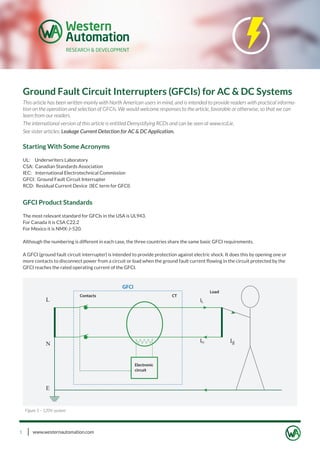
  • 1. www.westernautomation.com1 Ground Fault Circuit Interrupters (GFCIs) for AC & DC Systems This article has been written mainly with North American users in mind, and is intended to provide readers with practical informa- tion on the operation and selection of GFCIs. We would welcome responses to the article, favorable or otherwise, so that we can learn from our readers. The international version of this article is entitled Demystifying RCDs and can be seen at www.rcd.ie. See sister articles: Leakage Current Detection for AC & DC Application. Starting With Some Acronyms UL: Underwriters Laboratory CSA: Canadian Standards Association IEC: International Electrotechnical Commission GFCI: Ground Fault Circuit Interrupter RCD: Residual Current Device (IEC term for GFCI) GFCI Product Standards The most relevant standard for GFCIs in the USA is UL943. For Canada it is CSA C22.2 For Mexico it is NMX-J-520. Although the numbering is different in each case, the three countries share the same basic GFCI requirements. A GFCI (ground fault circuit interrupter) is intended to provide protection against electric shock. It does this by opening one or more contacts to disconnect power from a circuit or load when the ground fault current flowing in the circuit protected by the GFCI reaches the rated operating current of the GFCI. Figure 1 – 120V system
  • 2. www.westernautomation.com2 GFCIs for AC & DC Systems Figure 1 shows a typical 120V single phase configuration. Under normal conditions the current IL flowing from the supply to the load will be equal to the current IN flowing back from the load. Because these currents are of equal magnitude but flowing in opposite directions within the current transformer (CT), their vector sum will be zero and the CT will produce no output. If a person touches a live part as demonstrated in Figure 1, an additional current Ig will flow through the person’s body to ground and return to the supply via the ground or earth return path. The current IL will now be greater than IN by the value of Ig and the CT will produce a resultant output in response to this differential or residual current. This output will be sensed by the electronic circuit, and if it is above a predetermined level (typically 6mA) it will cause the GFCI contacts to open and disconnect the supply from the load and thereby provide protection. The differential current level at which the GFCI is designed to operate is known as its rated ground fault operating current, and can be designated as I�n, a term widely used in IEC documents. Figure 2 shows a typical 240V two line arrangement. In this case the voltage across L1 and L2 is 240V and this supply is used to supply high power loads, e.g. water heaters and cookers, etc. The centre of the supply transformer is connected to ground and this centre point is distributed as a neutral conductor. The voltage between N and L1 or L2 will be 120V, and this supply is used to power smaller loads, e.g. receptacle outlets and lighting circuits, etc. In this arrangement, all three current carrying conductors are passed through the CT. Under normal conditions the vector sum of all currents flowing through the CT will be zero. However in the event of a ground fault a differential current will flow back to the supply via earth, bypassing the CT. When this current exceeds the operating threshold of the GFCI the supply to all loads will be disconnected. In some GFCIs, the neutral may also have a switchable contact. It is worth noting that in this system the maximum touch voltage is 120V even though the installation uses a 240V supply. Figure 2 – 240V system
  • 3. www.westernautomation.com3 In the case of GFCIs, a ground fault current therefore refers to any current other than the load current. The ground fault current may flow through a person’s body or through a fault in equipment or wiring anywhere on the load side of the GFCI. The key factor in the ability of the GFCI to detect a ground fault current and provide protection is the connection of the supply neutral conductor to earth at the origin of the installation. Although the load current will typically be in the amperes range, the differential current I�n will generally be in the milliamps range. Typical maximum values of I�n in the USA are 6mA for personal shock protection, 30mA for equipment protection, and 300mA for fire protection. It is worth noting that the normal human body resistance for most people is in the range 1000 - 2000 Ohms, but for some people it may be as low as 500 ohms, so for a touch voltage of 120V the current through the body will generally be in excess of 50mA. 6mA versus 30mA Operating Thresholds. In the USA, the operating threshold for a GFCI for personal shock protection is 6mA. In most of the rest of the world, the threshold is 30mA. There are two reasons for this difference. The first relates to safety, and the second relates to technology. Tests on the human body have indicated that as the current is increased from zero mA, muscles tend to seize at about the 10mA level with the result that a person touching a live conductor may not be able to let go a live conductor at currents above 10mA. This is referred to as the “let-go” limit, and the North American GFCI standards decided to set the operating level of GFCIs at 6mA so as to have a comfortable safety margin below this threshold. At about 40mA, heart fibrillation starts to occur, which could lead to heart failure. European manufacturers decided to set 30mA as the operating level of RCDs (GFCIs) so as to have a comfortable safety margin below this threshold. This begs the question as to why the Europeans would set a higher level than the let-go level. The answer is Technology. North America uses electronic technology in their GFCIs, and it is relatively easy to set an operating threshold of 6mA for such devices. However, most European devices use electromechanical technology, and it is extremely difficult for such devices to operate at the 6mA level, so they chose 30mA because they can detect this level quite easily and it provides protection against heart fibrillation. European manufacturers had a substantially greater influence on IEC standards and practice, and the 30mA level has been adopted in most areas worldwide with the exception of North America. (See IEC60479 for more detailed information on the effect of current on the body) Double Grounded Neutral (DGN) Problem Figure 1 showed a typical situation whereby the GFCI provides protection. However, a condition that could prevent the GFCI from providing protection is represented in figure 3 below. GFCIs for AC & DC Systems Figure 3 – 120V system
  • 4. www.westernautomation.com4 This condition could arise due to miswiring or insulation breakdown. The fault current Ig will flow through the body as before, but will now split into two currents, Ige and Ign, with Ige flowing back to the supply via the earth or ground return path, and Ign re- turning back to the supply via the DGN fault connection and the neutral conductor. The ratio or division of these two currents will depend on the impedance of the neutral and ground paths. In many installations, the ground wire could be of smaller cross sectional area than the neutral wire with the result that Ige will be smaller than Ign. In any event, the CT will no longer see the total fault current and will only see Ige, and if Ige is less than the trip threshold of the GFCI, the device will not trip. UL943 requires GFCI manufacturers to provide an effective solution to this problem in that the GFCI must trip automatically or continue to provide protection under this condition. Figure 4 shows one example of how this can be achieved, but other mean are also used in practice. In the arrangement of figure 4, there is a second current transformer, CT2. Connected to this is an oscillator circuit which induces a current into CT2 winding. In this example, the oscillator produces a continuous current Iosc into CT2 winding. Under normal con- ditions, this current does nothing. However when the DGN fault occurs, a loop is formed by the neutral and earth paths, and Iosc is induced into this loop. CT1 see Iosc as a fault current and trips the GFCI. The DGN detecting circuit can function without an earth fault and without a load connected. GFCIs for AC & DC Systems Figure 4 – 120V system
  • 5. www.westernautomation.com5 The DC system may be totally isolated from ground, or may have one side connected to ground. If one side is connected to ground as shown by the dotted line, a person touching the +ve side of the supply will be exposed to a shock risk. In the case of a totally isolated system, if one side becomes inadvertently grounded, e.g. because of a first fault, a person touching the opposite side of the supply will be exposed to a shock risk. In either case, if a ground fault current above a certain level flows in the circuit, this will be detected and cause automatic opening of the contacts. It may seem strange to use a current transformer to detect a DC ground fault current. However this is achieved by driving the CT core into and out of saturation at a certain frequency, and using the DC fault current to generate a detectable change in the satura- tion characteristics. DC Sensing GFCIs DC ground fault currents can occur in installations powered from DC, such as • Mines • Tunnels • Solar panels • Electric vehicles • Ships • Aircraft, etc. DC currents through the body can be every bit as dangerous as AC currents and GFCI protection should be provided where shock risks exist. In IEC, GFCIs/RCDs that provide protection against both AC and DC ground fault currents are referred to as B Types. Commercial: Western Automation (WA) can provide GFCI solutions in the form of technology or GCFI products for use in AC & DC systems. GFCIs for AC & DC Systems Figure 5 – DC system
  • 6. www.westernautomation.com6 Types of GFCIs GFCI types can be categorised based on their construction, performance or configuration etc, as follows. Mounting • Panel Types – e.g. installed in panelboards • Receptacle Types – a receptacle incorporating a GFCI • Portable Types - fitted in a plug, an adaptor, or in a cord. The panel type GFCI may be single phase or three phase whereas the receptacle and portable types are generally single phase only. The panel types generally provide protection for part of or a complete installation. The receptacle and portable types provide protection for loads connected directly to the device. For this reason they are sometimes referred to as “point of use” GFCIs. Receptacle types provided with feed through terminals may also be used for protection of downstream receptacles. This is normal practice in the USA. Contacts The GFCI figures shown in this document have two contacts in each case. However, in practice, single pole GFCIs tend to use a single contact in the live pole, and an unswitched neutral pole. Portable GFCIs and receptacle based GFCIs break all poles. AC or DC Sensing GFCIs may also be categorised based on the type of ground fault current they can detect, e.g. detecting AC only, or detecting AC & DC fault currents. Trip Levels & Trip Times GFCIs covered by UL943 are known as Class A devices because their specified trip level (I�n) is in the range 4 – 6mA. The trip time specified in UL943 for GFCIs is derived from the following formula. T = (20/I)1.43 Where T = time in seconds I = ground fault current in milliamps The GFCI trip threshold combined with its response time are the most critical factors in minimising the risk of heart fibrillation and thereby providing protection of human life against the effects of electric shock. These two factors are addressed by the above formula. It is not easy to figure out from the formula what the trip time should be for say, 6mA, 20mA or 50mA, so we have produced figure 5 below to show the relationship between fault current and trip time. The graph provides a ready indication of the maximum trip time in relation to a given ground fault current. In practice, most GFCIs operate in less than 100mS regardless of the fault current level. GFCIs for AC & DC Systems Figure 6 - Maximum trip time in relation to a given ground fault current
  • 7. www.westernautomation.com7 Method Of Latching Latching is the means by which the contacts of the GFCI can be closed and held closed. GFCIs fall into the following two broad catego- ries: ML types that are Mechanically or Magnetically latching, and EL types that are Electrically latching. The ML device contacts can be closed and will remain closed regardless of whether or not a supply is present. The ML device may cease to operate in the event of loss of supply neutral. (see Problems with GFCIs) The EL type requires the presence of a supply above a certain voltage to enable its contacts to be closed (manually or automatically), and when the supply is reduced below a certain level the contacts open automatically. EL types fall into two categories: ELR and ELO types. The ELR GFCI opens automatically on loss of supply but recloses automatically on restoration of the supply (electrically latching and automatically reclosing when power is restored). It therefore provides protection against loss of supply neutral, but also recloses once the supply is restored. The ELO GFCI opens automatically on loss of supply and remains open on restoration of the supply (electrically latching and remaining open).The ELO also provides protection against loss of supply neutral. However, the ELO response is generally used in portable type GFCIs, and is not considered suitable for applications where power needs to be restored to equipment such as refrigerators, etc. Testing(see Problems with GFCIs) GFCIs are fitted with a test button to enable users to test the GFCI from time to time. In fact it is recommended that the GFCI be test- ed on a regular basis because if a GFCI fails for any reason, the user will not be aware of the failure unless the test button is operated. (see: Reliability – Design Factors) Selecting GFCIs Factors such as the rated voltage, load current, residual current and number of poles should be fairly obvious, so I will deal with some other factors. 1. AC, Rectified AC and DC In order to choose a GFCI the user or installer should first of all decide on the type of protection required. As an absolute minimum requirement, all GFCIs will provide protection against AC ground fault currents. However, if any type of power control is used on the load, e.g. speed control for electric drills, heat control for hair dryers or heaters, dimmer control for lighting, partial or complete rectification of the AC supply will be used within the equipment, and this could result in a ground fault current that is not pure AC, but rectified AC. Figure 6 shows examples of typical wave shapes produced by power controlled equipment. GFCIs for AC & DC Systems Wave shapes 1 – 6 represent different types of ground fault currents. Wave shape 1 is normal AC. Wave shapes 2 & 3 represent unipolar half wave rectified AC as produced by a diode or a thyristor. Wave shapes 4 & 5 represent unipolar quarter wave rectified AC as produced by a thyristor. Wave shapes 6 represents a bipolar quarter wave rectified AC as produced by a triac. 1. 2. 3. 4. 5. 6. Figure 7 - Wave shapes
  • 8. www.westernautomation.com8 UL943 requires GFCIs to provide protection in the case of wave shape 1 only, but does not presently contain any requirements or tests for protection against the fault currents represented by 2, 3, 4, 5 or 6. In IEC, RCDs (GFCIs) that provide protection against earth fault currents represented by wave shape 1 above are referred to as AC Types, and RCDs (GFCIs) that provide protection against earth fault currents represented by all of the above wave shapes are referred to as A Types. The use of A Type GFCIs is mandated in several countries such as Germany and the Netherlands, etc. because they be- lieve that AC Type GFCIs do not provide adequate shock protection. Another important point is that wave shapes 4, 5 & 6 have very fast rise times which can cause voltage or current spikes which may contribute to nuisance tripping in some GFCIs even in the absence of a fault. Some GFCIs can detect all of the above fault currents, but in any event it is also important that the GFCI is not prone to nuisance tripping in the presence of such wave shapes under non fault conditions. Commercial: WA offers GFCIs meeting the above requirements. Problems With GFCIs Whilst it is readily acknowledged that GFCIs provide a very high level of protection against electric shock, they can unfortunately suffer from some problems, mainly as follows. 1. Miswiring 2. Failure of user to test the device 3. Loss of supply Neutral 4. Poor Reliability 5. Nuisance Tripping 1.. Miswiring Problem for GFCI with feedthrough terminals GFCIs for AC & DC Systems Figure 8 – Correctly wired GFCI with feedthrough terminals
  • 9. www.westernautomation.com9 If the GFCI with feedthrough terminals is miswired as shown in figure 2, the GFCI will appear to provide protection because when the contacts are manually closed and the test button is operated the GFCI contacts will open. However the GFCI will not provide protec- tion in the event of a person touching a live conductor at the integrated socket outlet. Commercial: WA GFCIs cannot be closed if miswired. 2. Failure of user to test the device Field studies carried out in several countries worldwide, including the USA, have indicated that about 2 – 3% of installed RCDs/GFCIs were defective. In general the users were not aware of these failed devices because they did not test them regularly. UL now requires panel mounted and receptacle based GFCIs to indicate “end of life” if the device fails to trip when the test button is manually operated. It is expected that UL will also introduce requirements for self testing of GFCIs whereby the GFCI will carry out a test on itself at regular intervals and provide indication to the user of “end of life”. Commercial: WA GFCIs incorporate self testing of the device and end of life indication. 3. Loss of supply Neutral ELO and ELR type GFCI will open automatically on loss of supply neutral and therefore mitigate any shock risk under this supply condition. However, the ELO type needs to be manually reclosed after restoration of the supply, and this precludes its use in receptacle based GFCIs. The ML type GFCI will remain closed on loss of supply neutral but may not be able to provide protection under this condition if the live supply conductor is still connected. The risk of electric shock under this condition is considered to be minimal, but users should be aware of it. When the supply neutral is restored, the ML type will automatically provide protection again. GFCIs for AC & DC Systems Figure 9 – Incorrectly wired GFCI with feedthrough terminals
  • 10. www.westernautomation.com10 GFCIs for AC & DC Systems Commercial: WA offers New Hybrid Type GFCI. WA has developed a range of GFCIs that will open automatically on loss of supply neutral but will also reclose automatically on restoration of the supply, thus providing protection against a loss of neutral condition and avoiding the need for manual reclosing. 4. Poor Reliability Reliability is largely a function of design and use. A poorly designed GFCI will lead to poor reliability even if used as intended. However a well designed GFCI will generally be highly reliable when used as intended, but unfortunately its reliability may be compromised when used in unsuitable applications. Examples of unsuitable applications are cases where a GFCI intended for indoor use is used in areas with harsh environments, for example indus- trial areas or outdoors near swimming pools and farms, etc. Commercial: WA offers GFCIs for harsh environments – See below. GFCI for outdoor use. The above figures show a GFCI with a duplex receptacle fitted in a weather proof box. This product has the following unique features. 1. If the cover of a standard weather proof box is left open, the weather proof properties will be compromised. This box is fitted with an interlock to alert the user to when the cover is open. 2. The GFCI is fully visible and accessible from the outside of the box, so it is easy to see the status of the GFCI at all times, and to Test and Reset it as required. 3.The GFCI is fitted with STEOL (Self Test & End Of Life) functionality. The GFCI will carry out a Self Test every 2 – 3 seconds as indicat- ed by the ST LED, and in the event of GFCI failure, the EOL LED will light. The GFCI will automatically trip in the EOL state and remove power to the outlets. 1. 2. 3.
  • 11. www.westernautomation.com11 GFCIs for AC & DC Systems 5. Nuisance Tripping As far as users are concerned, the single greatest problem with GFCIs is nuisance tripping. Nuisance tripping can be a frustrating prob- lem for the user. Nuisance tripping problems can usually be attributed to the product itself or the protected circuit. Electrical disturbances such as volt- age transients occur continuously on the mains supply and can be caused by lightning or by switching. These disturbances can occur upstream or downstream of a GFCI, depending on its location in the installation. The protected circuit may have loads that produce voltage transients due to manual or automated switching (see reference above to wave shapes 4, 5 & 6), or loads that produce high inrush currents. A well designed GFCI should be able to tolerate such non fault occurrences, so in these cases the problem of nuisance tripping lies with the GFCI designer/manufacturer. Loads on installations may use RFI filtering to avoid inducing noise on to the mains supply. Such filtering can result in transient or standing leakage currents to ground. These problems can usually be traced to a specific load, e.g. washing machine, dish washer, etc. In North American homes most GFCIs have a trip level of 4mA - 6mA. A typical electrical appliance may produce a standing leakage current of 3 – 4mA which effectively primes the GFCI to trip. It could take just another 1 – 2mA from another load to trip the GFCI. In such cases the best solution may be to provide a dedicated point of use GFCI to protect that load. Nuisance tripping problems can often be resolved by selecting GFCIs with high immunity to nuisance tripping. This problem can also be alleviated by using GFCIs to protect separate circuits or subcircuits rather than an entire installation. Ideally, GFCIs should be used at the point of use because they will then be protecting a specific load rather than an installation. Portable and receptacle based GFCIs are ideal “point of use” devices. Commercial: WA Corp offers GFCIs with high immunity to nuisance tripping. About the author. Pat Ward is the owner manager of Western Automation R & D based in Ireland and President of WA Corporation USA. WA Corp is a specialist designer and manufacturer of GFCI technology & products for OEMs in the North American market. Pat has been an active member of technical committees in ETCI, IEC and CENELEC since 1991 and has been involved in the drafting of several international standards for GFCIs, AFCIs and LCDIs and has also participated in working groups within IEC addressing problems of reliability and EMC requirements for GFCIs and AFCIs, etc.