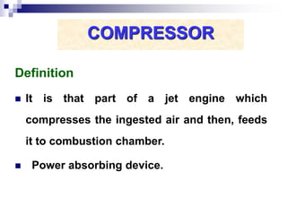
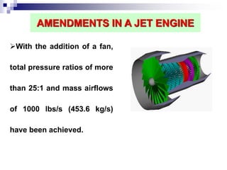
1. A compressor increases the mass flow rate of air through a jet engine by compressing the ingested air and feeding it to the combustion chamber. It works by imparting kinetic energy to the air through rotating blades, then converting this to increased static pressure.
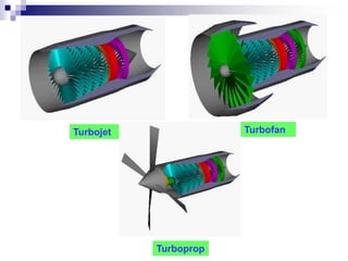
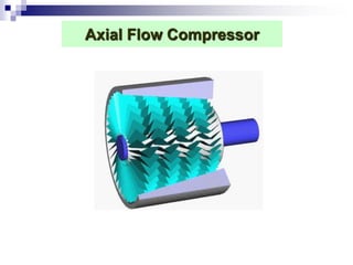
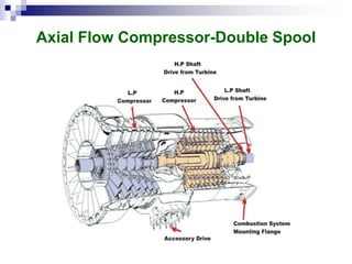
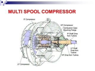
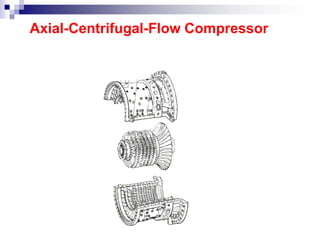
2. The two main types of compressors are centrifugal and axial flow. Centrifugal compressors force air outward radially from the center, while axial flow compressors maintain air flow parallel to the compressor shaft.
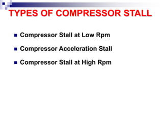
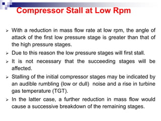
3. Key factors that affect compressor performance include aerofoil design, blade angles, clearance between blades and casing, and stability of operation over a range of conditions to avoid stall or surge. Higher pressure ratios, mass flow rates,


![SBP- Air compressor [Compatibility Mode].pdf](https://cdn.slidesharecdn.com/ss_thumbnails/sbp-aircompressorcompatibilitymode-241227102120-b6a67cde-thumbnail.jpg?width=640&height=640&fit=bounds)


