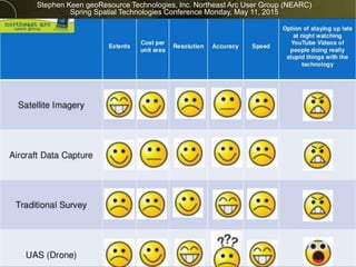
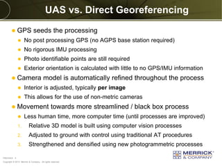
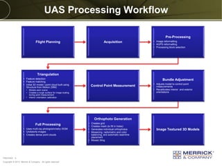
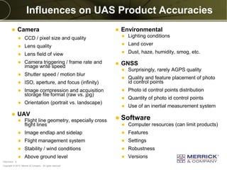
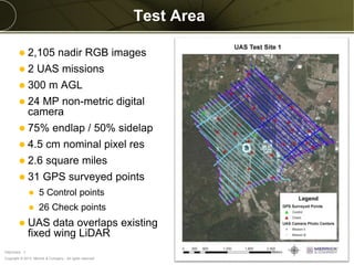
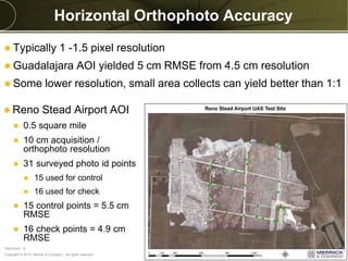
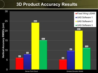
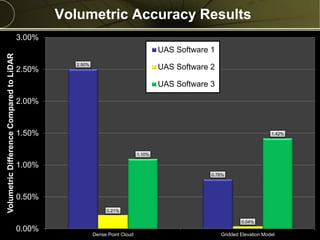
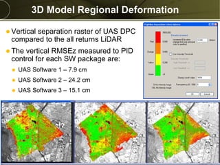
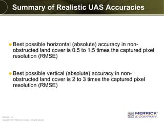
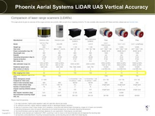
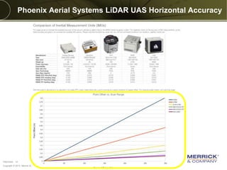
Engineering | Architecture | Design-Build | Surveying | Planning | GeoSpatial Solutions
April 26, 2016
GEOSPATIAL SOLUTIONS
Unmanned Aerial System (UAS)
Data Quality and Accuracy
Realities
Copyright © 2013 Merrick & Company - All rights reserved.
PREXXXX 2
Matt Bethel, GISP
Director of Technology for Merrick & Company
Copyright © 2013 Merrick & Company - All rights reserved.
PREXXXX 3
Stephen Keen geoResource Technologies, Inc. Northeast Arc User Group (NEARC)
Spring Spatial Technologies Conference Monday, May 11, 2015
Copyright © 2013 Merrick & Company - All rights reserved.
PREXXXX 4
UAS vs. Direct Georeferencing
 GPS seeds the processing
 No post processing GPS (no AGPS base station required)
 No rigorous IMU processing
 Photo identifiable points are still required
 Exterior orientation is calculated with little to no GPS/IMU information
 Camera model is automatically refined throughout the process
 Interior is adjusted, typically per image
 This allows for the use of non-metric cameras
 Movement towards more streamlined / black box process
 Less human time, more computer time (until processes are improved)
1. Relative 3D model is built using computer vision processes
2. Adjusted to ground with control using traditional AT procedures
3. Strengthened and densified using new photogrammetric processes
Copyright © 2013 Merrick & Company - All rights reserved.
PREXXXX 5
UAS Processing Workflow
Flight Planning Acquisition
Pre-Processing
• Image reformatting
• AGPS reformatting
• Processing block selection
Triangulation
• Feature detection
• Feature matching
• Initial 3D model / point cloud built using
Structure from Motion (SfM)
• Models each scene
• Creates a rough surface for image scaling
during point measurement
• Interior orientation calibration
Control Point Measurement
Bundle Adjustment
• Adjusts model to control point
measurements
• Recalibrates interior and exterior
orientations
Full Processing
• Uses multi-ray photogrammetry /SGM
• Undistorts images
• Creates dense point clouds
Orthophoto Generation
• Creates grid
• Creates mesh (to fill in holes)
• Generates individual orthophotos
• Mosaicing, radiometric and color
balancing, and automatic seamline
placement
• Mosaic tiling
Image Textured 3D Models
Copyright © 2013 Merrick & Company - All rights reserved.
PREXXXX 6
Influences on UAS Product Accuracies
 Camera
 CCD / pixel size and quality
 Lens quality
 Lens field of view
 Camera triggering / frame rate and
image write speed
 Shutter speed / motion blur
 ISO, aperture, and focus (infinity)
 Image compression and acquisition
storage file format (raw vs. jpg)
 Orientation (portrait vs. landscape)
 UAV
 Flight line geometry, especially cross
flight lines
 Image endlap and sidelap
 Flight management system
 Stability / wind conditions
 Above ground level
 Environmental
 Lighting conditions
 Land cover
 Dust, haze, humidity, smog, etc.
 GNSS
 Surprisingly, rarely AGPS quality
 Quality and feature placement of photo
id control points
 Photo id control points distribution
 Quantity of photo id control points
 Use of an inertial measurement system
 Software
 Computer resources (can limit products)
 Features
 Settings
 Robustness
 Versions
Copyright © 2013 Merrick & Company - All rights reserved.
PREXXXX 7
Test Area
 2,105 nadir RGB images
 2 UAS missions
 300 m AGL
 24 MP non-metric digital
camera
 75% endlap / 50% sidelap
 4.5 cm nominal pixel res
 2.6 square miles
 31 GPS surveyed points
 5 Control points
 26 Check points
 UAS data overlaps existing
fixed wing LiDAR
Copyright © 2013 Merrick & Company - All rights reserved.
PREXXXX 8
Horizontal Orthophoto Accuracy
 Reno Stead Airport AOI
 0.5 square mile
 10 cm acquisition /
orthophoto resolution
 31 surveyed photo id points
 15 used for control
 16 used for check
 15 control points = 5.5 cm
RMSE
 16 check points = 4.9 cm
RMSE
 Typically 1 -1.5 pixel resolution
 Guadalajara AOI yielded 5 cm RMSE from 4.5 cm resolution
 Some lower resolution, small area collects can yield better than 1:1
Copyright © 2013 Merrick & Company - All rights reserved.
PREXXXX 9
3D Product Accuracy Results
6.1
5.2
7.9
9.7
24.2
20.1
15.1
11.2
0
5
10
15
20
25
30
Dense Point Cloud Gridded Elevation Model
VerticalAccuracyRMSEz(cm)
Fixed Wing LiDAR
UAS Software 1
UAS Software 2
UAS Software 3
Copyright © 2013 Merrick & Company - All rights reserved.
PREXXXX 10
Volumetric Accuracy Results
2.50%
0.78%
0.21%
0.04%
1.10%
1.42%
0.00%
0.50%
1.00%
1.50%
2.00%
2.50%
3.00%
Dense Point Cloud Gridded Elevation Model
VolumetricDifferenceComparedtoLiDAR
UAS Software 1
UAS Software 2
UAS Software 3
Copyright © 2013 Merrick & Company - All rights reserved.
PREXXXX 11
3D Model Regional Deformation
 Vertical separation raster of UAS DPC
compared to the all returns LiDAR
 The vertical RMSEz measured to PID
control for each SW package are:
 UAS Software 1 – 7.9 cm
 UAS Software 2 – 24.2 cm
 UAS Software 3 – 15.1 cm
Meters
Copyright © 2013 Merrick & Company - All rights reserved.
PREXXXX 12
Summary of Realistic UAS Accuracies
 Best possible horizontal (absolute) accuracy in non-
obstructed land cover is 0.5 to 1.5 times the captured pixel
resolution (RMSE)
 Best possible vertical (absolute) accuracy in non-
obstructed land cover is 2 to 3 times the captured pixel
resolution (RMSE)
Copyright © 2013 Merrick & Company - All rights reserved.
PREXXXX 13
Phoenix Aerial Systems LiDAR UAS Vertical Accuracy
Copyright © 2013 Merrick & Company - All rights reserved.
PREXXXX 14
Phoenix Aerial Systems LiDAR UAS Horizontal Accuracy
Copyright © 2013 Merrick & Company - All rights reserved.
PREXXXX 15
LiDAR UAS
Copyright © 2013 Merrick & Company - All rights reserved.
PREXXXX 16
Contact Info
Matt Bethel
Director of Technology
Merrick & Company
www.merrick.com
matt.bethel@merrick.com
(303) 353-3662

Unmanned Aerial Systems (UAS) Data Quality and Accuracy Realities

  • 1.
    Engineering | Architecture| Design-Build | Surveying | Planning | GeoSpatial Solutions April 26, 2016 GEOSPATIAL SOLUTIONS Unmanned Aerial System (UAS) Data Quality and Accuracy Realities
  • 2.
    Copyright © 2013Merrick & Company - All rights reserved. PREXXXX 2 Matt Bethel, GISP Director of Technology for Merrick & Company
  • 3.
    Copyright © 2013Merrick & Company - All rights reserved. PREXXXX 3 Stephen Keen geoResource Technologies, Inc. Northeast Arc User Group (NEARC) Spring Spatial Technologies Conference Monday, May 11, 2015
  • 4.
    Copyright © 2013Merrick & Company - All rights reserved. PREXXXX 4 UAS vs. Direct Georeferencing  GPS seeds the processing  No post processing GPS (no AGPS base station required)  No rigorous IMU processing  Photo identifiable points are still required  Exterior orientation is calculated with little to no GPS/IMU information  Camera model is automatically refined throughout the process  Interior is adjusted, typically per image  This allows for the use of non-metric cameras  Movement towards more streamlined / black box process  Less human time, more computer time (until processes are improved) 1. Relative 3D model is built using computer vision processes 2. Adjusted to ground with control using traditional AT procedures 3. Strengthened and densified using new photogrammetric processes
  • 5.
    Copyright © 2013Merrick & Company - All rights reserved. PREXXXX 5 UAS Processing Workflow Flight Planning Acquisition Pre-Processing • Image reformatting • AGPS reformatting • Processing block selection Triangulation • Feature detection • Feature matching • Initial 3D model / point cloud built using Structure from Motion (SfM) • Models each scene • Creates a rough surface for image scaling during point measurement • Interior orientation calibration Control Point Measurement Bundle Adjustment • Adjusts model to control point measurements • Recalibrates interior and exterior orientations Full Processing • Uses multi-ray photogrammetry /SGM • Undistorts images • Creates dense point clouds Orthophoto Generation • Creates grid • Creates mesh (to fill in holes) • Generates individual orthophotos • Mosaicing, radiometric and color balancing, and automatic seamline placement • Mosaic tiling Image Textured 3D Models
  • 6.
    Copyright © 2013Merrick & Company - All rights reserved. PREXXXX 6 Influences on UAS Product Accuracies  Camera  CCD / pixel size and quality  Lens quality  Lens field of view  Camera triggering / frame rate and image write speed  Shutter speed / motion blur  ISO, aperture, and focus (infinity)  Image compression and acquisition storage file format (raw vs. jpg)  Orientation (portrait vs. landscape)  UAV  Flight line geometry, especially cross flight lines  Image endlap and sidelap  Flight management system  Stability / wind conditions  Above ground level  Environmental  Lighting conditions  Land cover  Dust, haze, humidity, smog, etc.  GNSS  Surprisingly, rarely AGPS quality  Quality and feature placement of photo id control points  Photo id control points distribution  Quantity of photo id control points  Use of an inertial measurement system  Software  Computer resources (can limit products)  Features  Settings  Robustness  Versions
  • 7.
    Copyright © 2013Merrick & Company - All rights reserved. PREXXXX 7 Test Area  2,105 nadir RGB images  2 UAS missions  300 m AGL  24 MP non-metric digital camera  75% endlap / 50% sidelap  4.5 cm nominal pixel res  2.6 square miles  31 GPS surveyed points  5 Control points  26 Check points  UAS data overlaps existing fixed wing LiDAR
  • 8.
    Copyright © 2013Merrick & Company - All rights reserved. PREXXXX 8 Horizontal Orthophoto Accuracy  Reno Stead Airport AOI  0.5 square mile  10 cm acquisition / orthophoto resolution  31 surveyed photo id points  15 used for control  16 used for check  15 control points = 5.5 cm RMSE  16 check points = 4.9 cm RMSE  Typically 1 -1.5 pixel resolution  Guadalajara AOI yielded 5 cm RMSE from 4.5 cm resolution  Some lower resolution, small area collects can yield better than 1:1
  • 9.
    Copyright © 2013Merrick & Company - All rights reserved. PREXXXX 9 3D Product Accuracy Results 6.1 5.2 7.9 9.7 24.2 20.1 15.1 11.2 0 5 10 15 20 25 30 Dense Point Cloud Gridded Elevation Model VerticalAccuracyRMSEz(cm) Fixed Wing LiDAR UAS Software 1 UAS Software 2 UAS Software 3
  • 10.
    Copyright © 2013Merrick & Company - All rights reserved. PREXXXX 10 Volumetric Accuracy Results 2.50% 0.78% 0.21% 0.04% 1.10% 1.42% 0.00% 0.50% 1.00% 1.50% 2.00% 2.50% 3.00% Dense Point Cloud Gridded Elevation Model VolumetricDifferenceComparedtoLiDAR UAS Software 1 UAS Software 2 UAS Software 3
  • 11.
    Copyright © 2013Merrick & Company - All rights reserved. PREXXXX 11 3D Model Regional Deformation  Vertical separation raster of UAS DPC compared to the all returns LiDAR  The vertical RMSEz measured to PID control for each SW package are:  UAS Software 1 – 7.9 cm  UAS Software 2 – 24.2 cm  UAS Software 3 – 15.1 cm Meters
  • 12.
    Copyright © 2013Merrick & Company - All rights reserved. PREXXXX 12 Summary of Realistic UAS Accuracies  Best possible horizontal (absolute) accuracy in non- obstructed land cover is 0.5 to 1.5 times the captured pixel resolution (RMSE)  Best possible vertical (absolute) accuracy in non- obstructed land cover is 2 to 3 times the captured pixel resolution (RMSE)
  • 13.
    Copyright © 2013Merrick & Company - All rights reserved. PREXXXX 13 Phoenix Aerial Systems LiDAR UAS Vertical Accuracy
  • 14.
    Copyright © 2013Merrick & Company - All rights reserved. PREXXXX 14 Phoenix Aerial Systems LiDAR UAS Horizontal Accuracy
  • 15.
    Copyright © 2013Merrick & Company - All rights reserved. PREXXXX 15 LiDAR UAS
  • 16.
    Copyright © 2013Merrick & Company - All rights reserved. PREXXXX 16 Contact Info Matt Bethel Director of Technology Merrick & Company www.merrick.com matt.bethel@merrick.com (303) 353-3662

Editor's Notes

  • #4 Northeast Arc User Group (NEARC) Stephen Keen geoResource Technologies, Inc. NEARC Spring Spatial Technologies Conference Monday, May 11, 2015
  • #5 I really liked a quote that Rudi Wagner, imaging product manager for Leica Geosystems recently told me – “Photogrammetry will be used more in the future, but you just won’t see it.”
  • #7 Mirrorless Sony Nex and Alpha product line Nex 5 – 14MP Nex 5N – 16MP Nex 7 – 24MP A7 II – 24MP A7R – 36MP A7R II – 42MP Turn off auto focus