Download as PDF, PPTX

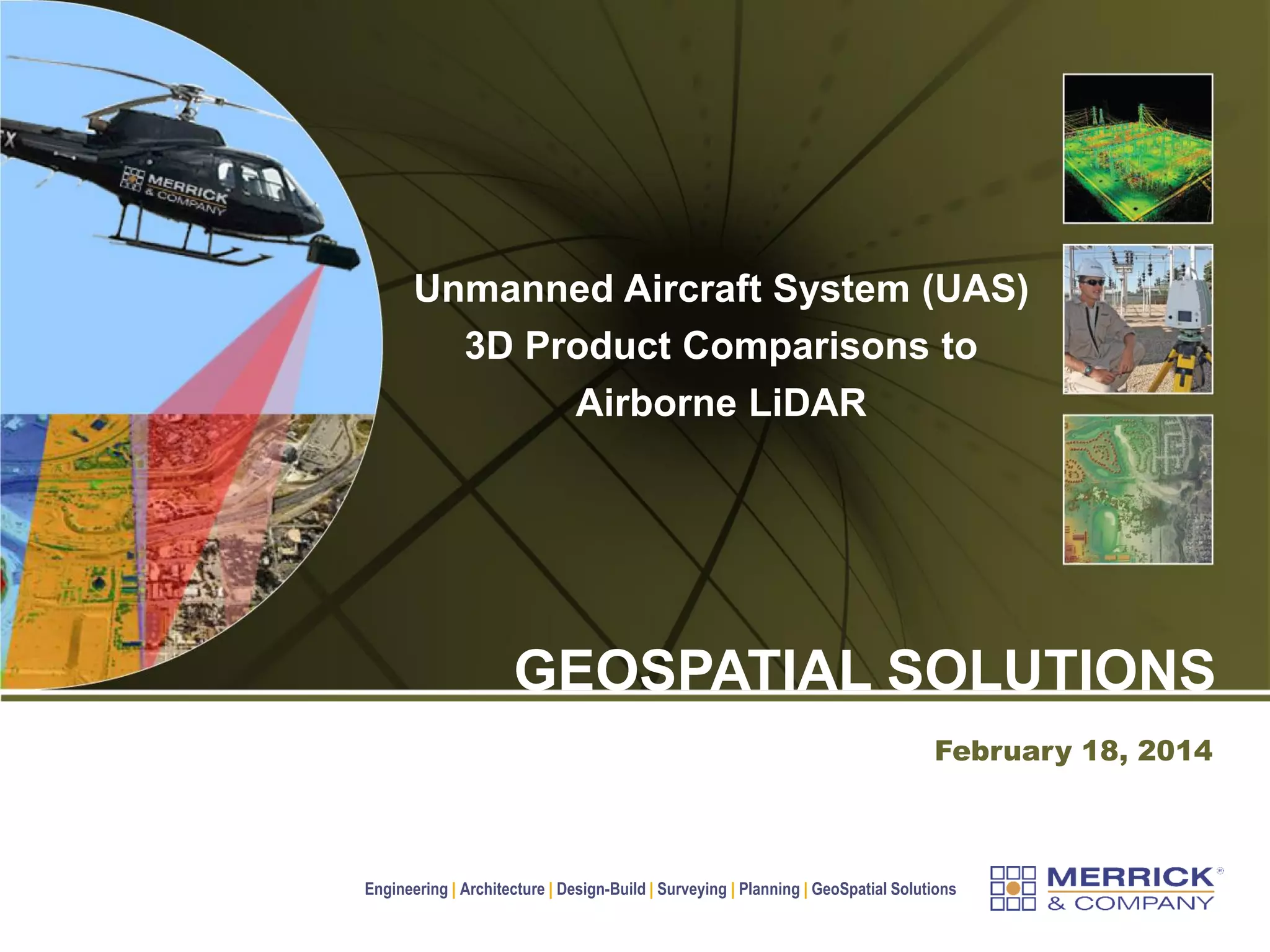


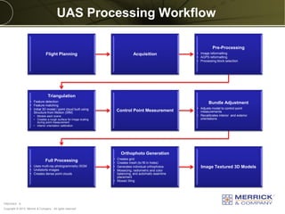
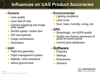
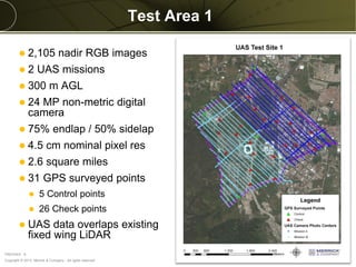
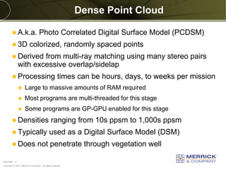
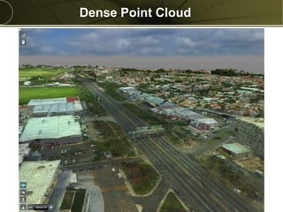
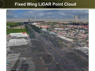
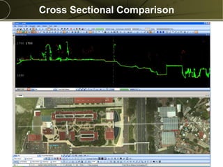
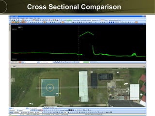
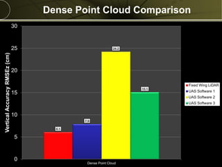
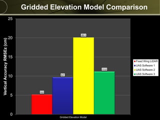
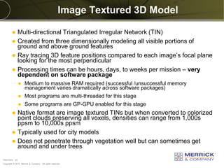
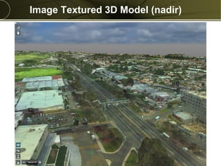
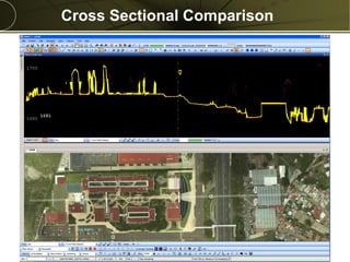
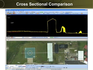
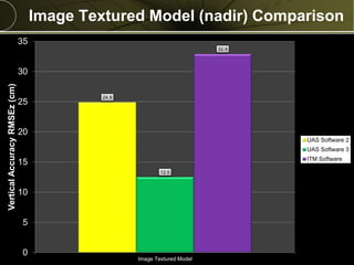
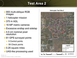
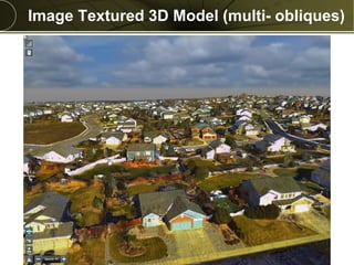


The document discusses the use of Unmanned Aircraft Systems (UAS) for 3D imaging and compares their performance to traditional airborne LiDAR systems. It outlines the UAS workflow, factors influencing accuracy, and includes specific comparisons of point clouds and elevation models derived from both technologies. Additionally, it addresses future considerations regarding accuracy and operational efficiencies in UAS processing.


