Downloaded 544 times


![10 Anvil International, Piping & Pipe Hanger Design and Engineering www.anvilintl.com
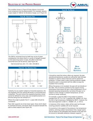
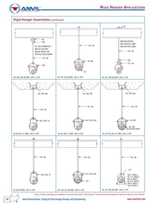
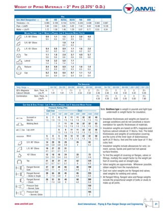
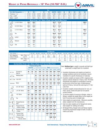
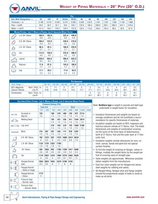
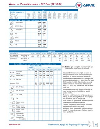
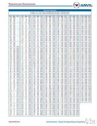
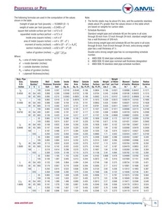
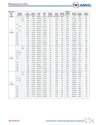
HANGER LOAD CALCULATIONS
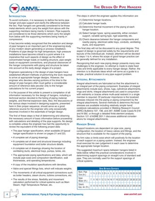
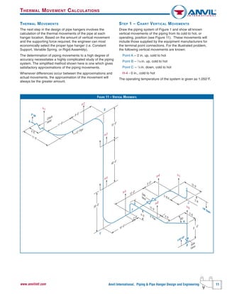
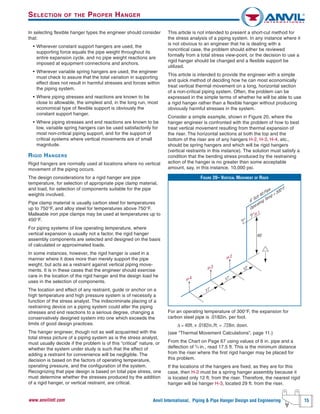
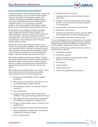
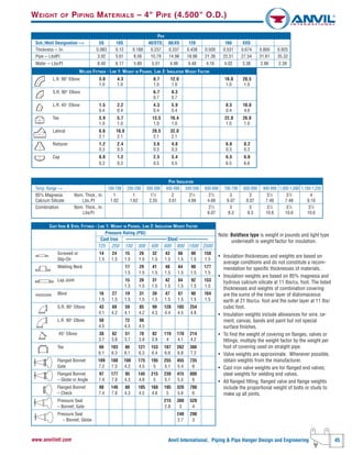
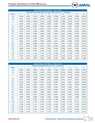
CALCULATED ARC DISTANCES FOR BENDS AND WELDING ELBOWS
0.0
0.2
0.1
0.3
0.4
0.6
0.8
1.0
1.1
1.2
0.5
0.7
0.9
0 10 20 30 40 50 60 70 80 90 100 110 120 130 140 150 160 170 180
"D" Curve
"E" Curve
TE
R
A
D
cg
T
E
D
θ
θ/2
D = R x [TAN(θ/2) + 2/θ - 2 x CSC(θ)]
E = 2 x R x [CSC(θ) 1/θ]
T = R x TAN(θ/2)
CENTER OF GRAVITY OF AN ARC
0.0
0.2
0.1
0.3
0.4
0.6
0.8
1.0
0.5
0.7
0.9
0 10 20 30 40 50 60 70 80 90 100 110 120 130 140 150 160 170 180
"A" Curve
"C" Curve
"B" Curve
B
C
cg
R
A
θ/2
θ
A = [2 x R x SIN(θ/2)]
θ
B = R x [1 - COS(θ)
θ
C = R x SIN(θ)
θ
A,B&CinInchesfor1"Radius
ø in Degrees
D&EinInchesfor1"Radius
ø in Degrees](https://image.slidesharecdn.com/178680732-pipe-hanger-design-141104044635-conversion-gate02/85/178680732-pipe-hanger-design-10-320.jpg)
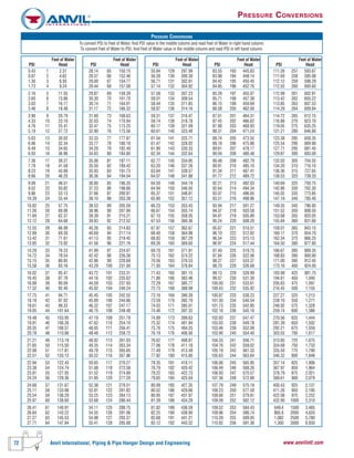
![28 Anvil International, Piping & Pipe Hanger Design and Engineering www.anvilintl.com
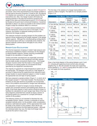
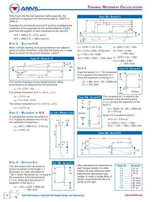
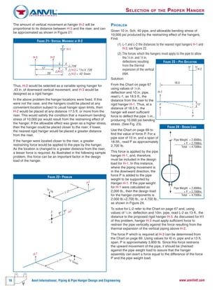
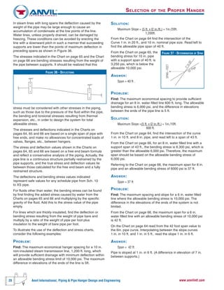
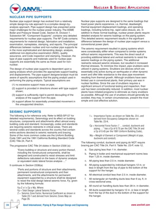
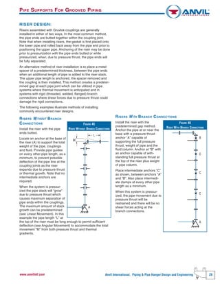
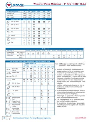
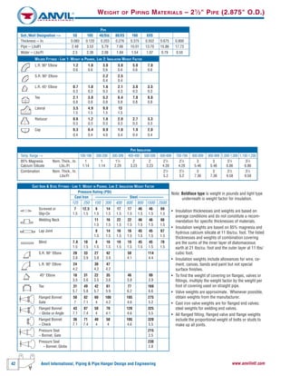
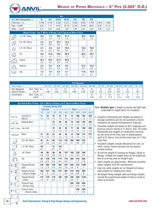
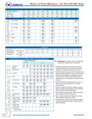
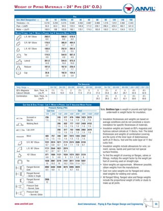
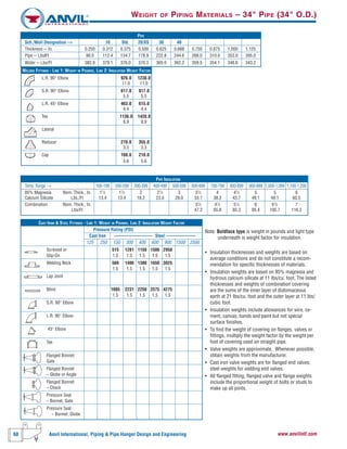
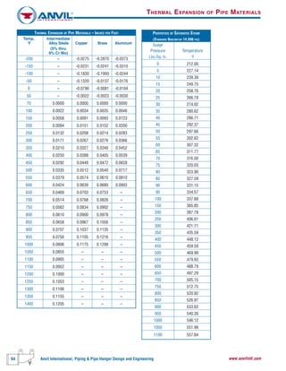
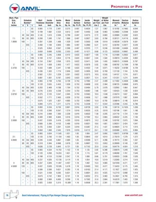
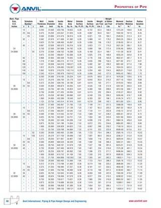
Figure 40 - The coupling joints have been installed butted or
partially open. When pressurized the pipe ends in the coupling
joints will separate to the maximum amount permitted by the
coupling design.
The coupling key sections will make contact with the groove
walls and restrain the pipe from further separation.
The movement at each coupling joint will add with all other
joints and produce ΔL.
Figure 41 - In the system shown here, the pipe will move and
deflect at the elbow joint due to pressure thrust.
The pipe designer must assure himself that the system has the
capability of deflecting sufficiently to absorb this movement
without introducing additional stresses into the pipe system.
In the deflected condition shown, temperature increases would
produce further expansion of the pipe system thus increasing
the deflection.
Figure 42 - To restrain this system provide a pressure thrust
anchor at “R1” to resist the pressure thrust acting through the
tee “D1” at the cap “C”. Provide a hanger at Point “R2”, or a
base support at Point “D2” to support the vertical column. If the
offsets L1, L2, and L3 are of adequate length to handle
expected pipe movements, no additional anchoring is required.
Thermal movement of the pipe system should also be
considered, and intermediate anchors located as required, to
direct the pipe movement so as to prevent introducing bending
stresses into the system.
Figure 43 - Anchor at “A” to support weight of vertical water
column. Use spring hanger at “D” and “E” to allow movement
of vertical piping.
Anchors at “B” and “C” if offsets at L1and L2 are insufficiently
long to handle expected pipe movements.
Figure 44 [Lateral Restraint] - A grooved coupling joint
installed in a partially deflected condition between anchor
locations will deflect to its fully deflected condition when
pressurized. Hangers and supports must be selected with
consideration of the hanger’s capability to provide lateral
restraint.
Light duty hangers, while acceptable in many installations,
may deflect against the application of lateral forces and result
in “snaking” conditions of the pipe system.
FIGURE 40 - PRESSURE THRUST
System With No Pressure
ΔL
System Pressurized
FIGURE 41 - PRESSURE THRUST
ΔM-MOVEMENT DUE
TO PRESSURE THRUST
SUFFICIENT LENGTH
TO OFFSET
PRESSURE THRUST
FIGURE 42 - PRESSURE THRUST
L2
D2
D1
R C
2R1
L3
L1
FIGURE 43 - PRESSURE THRUST
FIGURE 44 - LATERAL RESTRAINT
System with no pressure
partially deflected
System pressurized
fully deflected
PIPE SUPPORTS FOR GROOVED PIPING
L2
L1
E
C
A
D
B
VERTICAL
COLUMN
VERTICAL
COLUMN
HORIZONTAL RUN](https://image.slidesharecdn.com/178680732-pipe-hanger-design-141104044635-conversion-gate02/85/178680732-pipe-hanger-design-28-320.jpg)


This document provides guidance on designing pipe hangers and supports. It discusses determining hanger locations based on pipe size and configuration. It describes calculating hanger loads based on the weight of pipe, fittings, valves, and insulation. It also addresses calculating thermal movement of piping at hanger locations. The document provides information on selecting appropriate hangers based on the loads and movements, including spring hangers. It includes sample problems demonstrating how to apply the guidance. An extensive section lists the weights of common piping materials to aid in load calculations. The document is intended as a reference for engineers involved in pipe hanger and support design.


![[Point] pipe stress analysis by computer-caesar ii](https://cdn.slidesharecdn.com/ss_thumbnails/point-pipestressanalysisbycomputer-caesarii-150407122607-conversion-gate01-thumbnail.jpg?width=640&height=640&fit=bounds)


