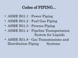
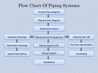
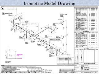
PIPING SYSTEMS
What is PIPING???
PIPING is a system of pipes used to
convey Fluids(Liquids & Fluids) from one
place to another.
It consists of various components such
as Pipes, fittings, flanges, valves,
instruments, etc.
Codes of PIPING...
• ASME B31.1 - Power Piping
• ASME B31.2 - Fuel Gas Piping
• ASME B31.3 - Process Piping
• ASME B31.4 - Pipeline Transportation
System for Liquids
• ASME B31.8 - Gas Transmissions and
Distribution Piping Systems
Process Flow Diagram
Flow Chart Of Piping Systems
Piping & Inst. Diagram
Equipment Layout
Piping General Arrangement
Isometric Drawings
Spools Fabrications Piping Support
Purchase Specification
Material Take Off
Installation
Piping Support GAD
Fabrication Drawings
Purchasing
Piping Work Flow
• Design & Engineering
• Procurement
• Fabrication
• Erection & Alignment
• Hydro testing & Pre-Commissioning
• Commissioning.
Design & Engineering
Drawings:-
• Process Flow Diagram
• Piping & Inst. Diagram (P&ID)
• General Arrangement Drawing (GAD)
• Isometric Drawing
• Piping Support Drawing.
Process Flow Model Digram
Piping & Instrumentation Model Diagram
Isometric Model Drawing
Components in PIPING
• Pipes
• Fittings(Elbow, Tee, Reducer, Coupling, Olets)
• Flanges
• Valves
• Fasteners
• Speciality items (Strainers, Traps, Bellows)
• Instruments (Pressure Gauge, Indicators, etc).
Diff. Between Pipe and Tube
PIPE
It is a tubular product of circular cross section
that has specific sizes and thickness governed by
particular dimensional standards.
TUBE
It is a hollow product having circular, elliptical
or square cross section or cross section of the any
closed perimeter. Tubes are also used for heat
transfer purpose.
Nominal Pipe Size (NPS)
• Pipes are designated by Nominal size, starting
from 1/18” nominal size.
• For the nominal size upto including 12” there
is one unique OD(Diff. from nominal size) and
ID would vary depending on the schedule of
the pipe.
• For nominal sizes 14” and above, OD is equal
to Nominal size.
Fittings
• Pipe fittings are the components which
tie together pipelines, valves, and other
parts of a piping system.
• Fittings may come in butt Welded,
Socket welded, screwed and flanged
connections.
• They are used to change the size of the
line or its direction.
Standard Pipe Fittings
BUTT WELD/SOCKET WELD/SCREWED/FLANGED
TYPES
ELBOW TEE REDUCER STUB END END CAP
SWAGE COUPLING UNION SPECIAL
FITTINGS
90* 45*
EQUAL UNEQUAL
CONCENTRIC ECCENTRIC
LONG SHORT
CONCENTRIC ECCENTRIC
FULL HALF REDUCING
LATROLET
WELDOLET THREADOLET
SOCKOLET NIPPOLET SWEEPOLET
ELBOWS
TEES
REDUCERS
STUB END
COUPLINGS UNION
Various Types of Fittings
Various Types of Olets
Flanges
A pipe flange is a disc, collar or ring
that attaches to pipe with the purpose of
providing increased support for
strength, blocking off a pipeline or
implementing the attachment of more
items. They are usually welded or
screwed to the pipe end and are
connected with bolts.
Types of Flanges
• Weld Neck
• Socket Weld
• Lap Joint
• Threaded
• Slip-On
• Blind
Types of Flanges
WELD NECK SOCKET WELD
LAP JOINT THREADED
SLIP-ON BLIND
Valves
Valves are installed in between the
pipes/equipment to perform following
functions:-
• Isolation (Gate, Ball, Butterfly)
• Regulation (Globe, Needle)
• Non-return (Check, SDNR)
• Special purpose (Foot)
Types Of Valves
BALL GATE GLOBE
CHECK (Lift type)
BUTTERFLY NEEDLE
Operations
• Cutting
• Bending
• Forming
• Welding
Cutting and bevelling of the edges by
Mechanical Methods (lathes,grinding Wheels /
Thermal methods (oxy – fuel gas cutting, Arc
cutting).
Non-Destructive Test
NDT is conducting in piping for check
the quality of welded joints/components.
•Radiography
•Ultrasonic
•Magnetic-particle
•Liquid Penetration
•Hydro & Pneumatic.
Types Of NDT
RADIOGRAPHY ULTRASONIC
LIQUID PENETRANT MAGNETIC PARTICLE
Testing Of Piping Systems
Piping system can be tested for leak
tightness and pressure integrity by hydro
test / pneumatic test methods.
Hydro-testing
1.5 Design Pressure x stress value at test temp
TEST PRESSURE
stress value at design temperature
TEST DURATION
A leak test shall be maintained for at least 10 minutes,
and all joints may be examined for leaks.
TEST MEDIUM
Water at ambient temperature is the test medium. Incase
of possibility of freezing exists, other fluids may be used.
Pneumatic Testing
1.1 Design Pressure X stress value at test
temp
TEST PRESSURE
stress value at design temperature
TEST DURATION
A leak test shall be maintained for at least 10
minutes, and all joints may be examined for leaks.
TEST MEDIUM
Air at ambient temperature is the test medium.
Defects
Safety Points
• Drain the pipe line only when top outlet
is kept Open.
• Use minimum 2 Gauges for any hydro-
testing.
• Never use high discharge pumps for
testing low volume pipe(Vol. <10 M ).
• Never pressurize any line above the test
pressure.
3
Thank You

PIPING SYSTEMS, components, basic fundamentals

  • 1.
  • 2.
    What is PIPING??? PIPINGis a system of pipes used to convey Fluids(Liquids & Fluids) from one place to another. It consists of various components such as Pipes, fittings, flanges, valves, instruments, etc.
  • 3.
    Codes of PIPING... •ASME B31.1 - Power Piping • ASME B31.2 - Fuel Gas Piping • ASME B31.3 - Process Piping • ASME B31.4 - Pipeline Transportation System for Liquids • ASME B31.8 - Gas Transmissions and Distribution Piping Systems
  • 4.
    Process Flow Diagram FlowChart Of Piping Systems Piping & Inst. Diagram Equipment Layout Piping General Arrangement Isometric Drawings Spools Fabrications Piping Support Purchase Specification Material Take Off Installation Piping Support GAD Fabrication Drawings Purchasing
  • 5.
    Piping Work Flow •Design & Engineering • Procurement • Fabrication • Erection & Alignment • Hydro testing & Pre-Commissioning • Commissioning.
  • 6.
    Design & Engineering Drawings:- •Process Flow Diagram • Piping & Inst. Diagram (P&ID) • General Arrangement Drawing (GAD) • Isometric Drawing • Piping Support Drawing.
  • 7.
  • 8.
  • 9.
  • 10.
    Components in PIPING •Pipes • Fittings(Elbow, Tee, Reducer, Coupling, Olets) • Flanges • Valves • Fasteners • Speciality items (Strainers, Traps, Bellows) • Instruments (Pressure Gauge, Indicators, etc).
  • 11.
    Diff. Between Pipeand Tube PIPE It is a tubular product of circular cross section that has specific sizes and thickness governed by particular dimensional standards. TUBE It is a hollow product having circular, elliptical or square cross section or cross section of the any closed perimeter. Tubes are also used for heat transfer purpose.
  • 12.
    Nominal Pipe Size(NPS) • Pipes are designated by Nominal size, starting from 1/18” nominal size. • For the nominal size upto including 12” there is one unique OD(Diff. from nominal size) and ID would vary depending on the schedule of the pipe. • For nominal sizes 14” and above, OD is equal to Nominal size.
  • 13.
    Fittings • Pipe fittingsare the components which tie together pipelines, valves, and other parts of a piping system. • Fittings may come in butt Welded, Socket welded, screwed and flanged connections. • They are used to change the size of the line or its direction.
  • 14.
    Standard Pipe Fittings BUTTWELD/SOCKET WELD/SCREWED/FLANGED TYPES ELBOW TEE REDUCER STUB END END CAP SWAGE COUPLING UNION SPECIAL FITTINGS 90* 45* EQUAL UNEQUAL CONCENTRIC ECCENTRIC LONG SHORT CONCENTRIC ECCENTRIC FULL HALF REDUCING LATROLET WELDOLET THREADOLET SOCKOLET NIPPOLET SWEEPOLET
  • 15.
  • 16.
  • 17.
    Flanges A pipe flangeis a disc, collar or ring that attaches to pipe with the purpose of providing increased support for strength, blocking off a pipeline or implementing the attachment of more items. They are usually welded or screwed to the pipe end and are connected with bolts.
  • 18.
    Types of Flanges •Weld Neck • Socket Weld • Lap Joint • Threaded • Slip-On • Blind
  • 19.
    Types of Flanges WELDNECK SOCKET WELD LAP JOINT THREADED SLIP-ON BLIND
  • 20.
    Valves Valves are installedin between the pipes/equipment to perform following functions:- • Isolation (Gate, Ball, Butterfly) • Regulation (Globe, Needle) • Non-return (Check, SDNR) • Special purpose (Foot)
  • 21.
    Types Of Valves BALLGATE GLOBE CHECK (Lift type) BUTTERFLY NEEDLE
  • 22.
    Operations • Cutting • Bending •Forming • Welding Cutting and bevelling of the edges by Mechanical Methods (lathes,grinding Wheels / Thermal methods (oxy – fuel gas cutting, Arc cutting).
  • 23.
    Non-Destructive Test NDT isconducting in piping for check the quality of welded joints/components. •Radiography •Ultrasonic •Magnetic-particle •Liquid Penetration •Hydro & Pneumatic.
  • 24.
    Types Of NDT RADIOGRAPHYULTRASONIC LIQUID PENETRANT MAGNETIC PARTICLE
  • 25.
    Testing Of PipingSystems Piping system can be tested for leak tightness and pressure integrity by hydro test / pneumatic test methods.
  • 26.
    Hydro-testing 1.5 Design Pressurex stress value at test temp TEST PRESSURE stress value at design temperature TEST DURATION A leak test shall be maintained for at least 10 minutes, and all joints may be examined for leaks. TEST MEDIUM Water at ambient temperature is the test medium. Incase of possibility of freezing exists, other fluids may be used.
  • 27.
    Pneumatic Testing 1.1 DesignPressure X stress value at test temp TEST PRESSURE stress value at design temperature TEST DURATION A leak test shall be maintained for at least 10 minutes, and all joints may be examined for leaks. TEST MEDIUM Air at ambient temperature is the test medium.
  • 28.
  • 29.
    Safety Points • Drainthe pipe line only when top outlet is kept Open. • Use minimum 2 Gauges for any hydro- testing. • Never use high discharge pumps for testing low volume pipe(Vol. <10 M ). • Never pressurize any line above the test pressure. 3
  • 30.