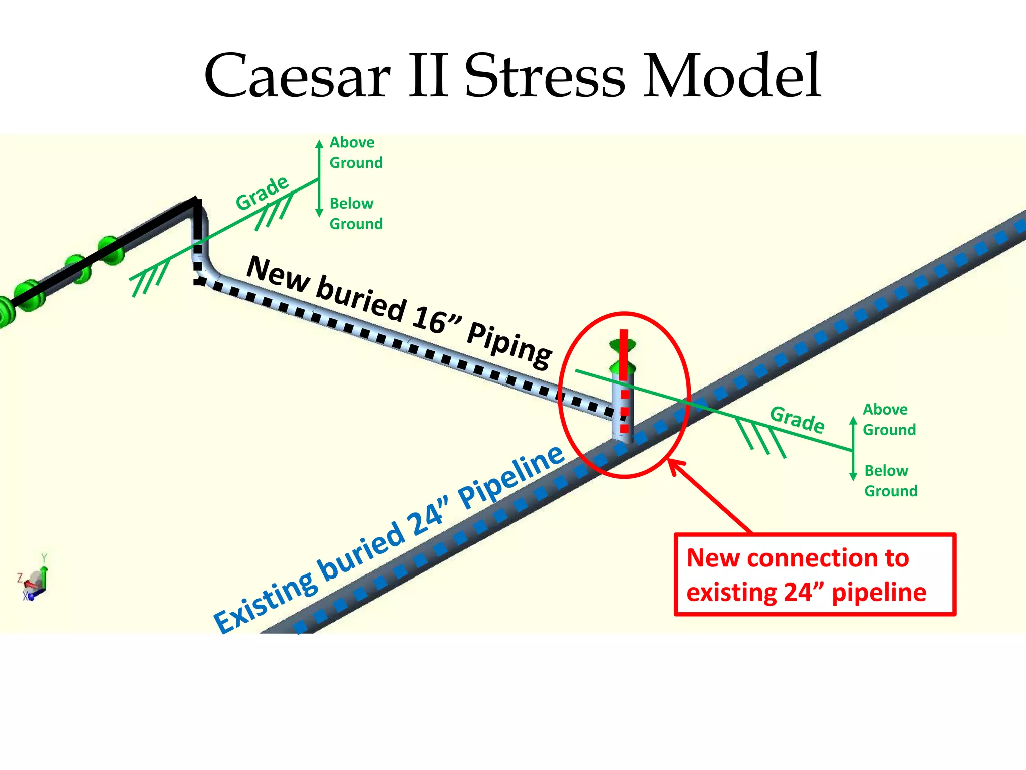
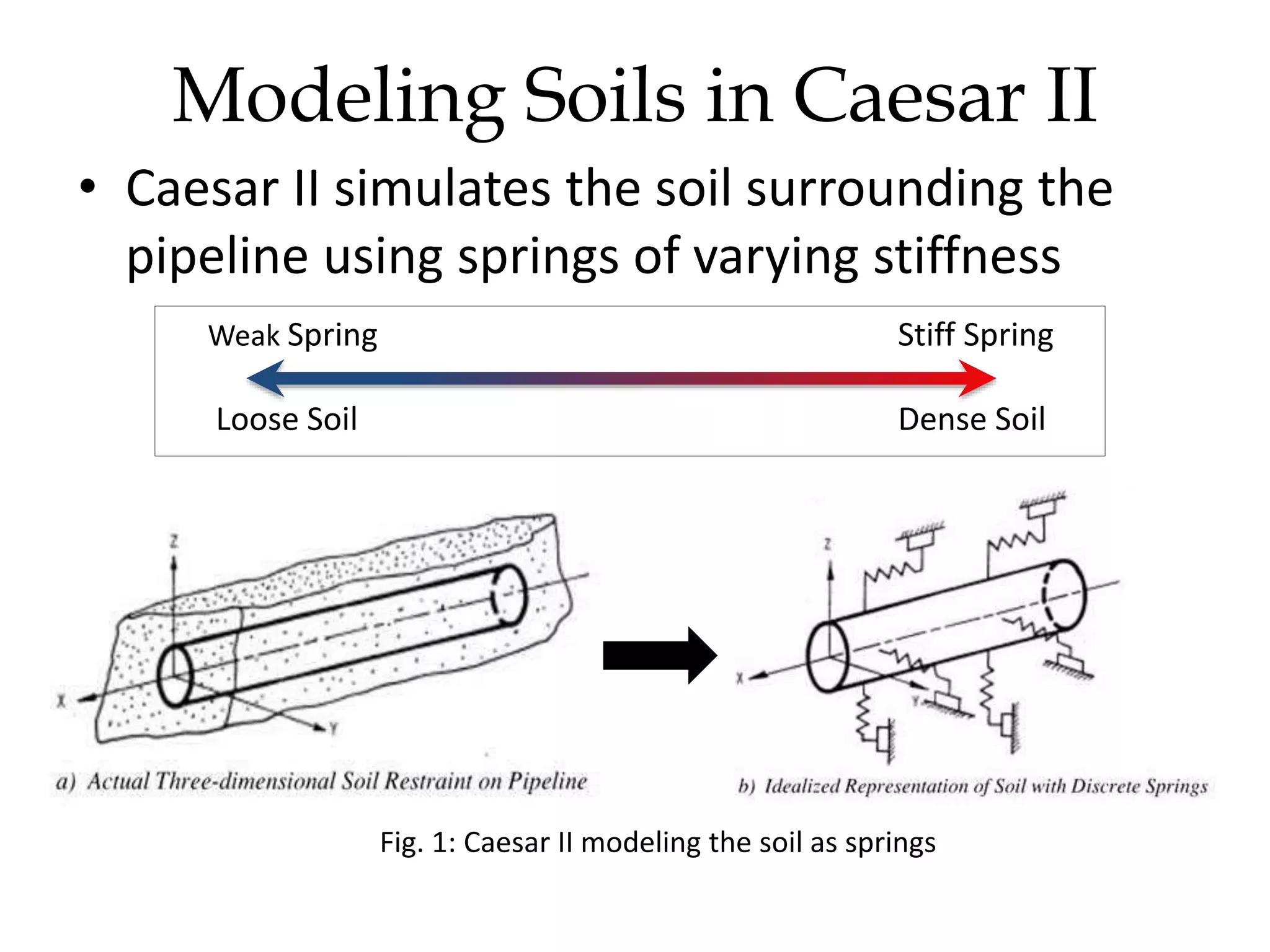
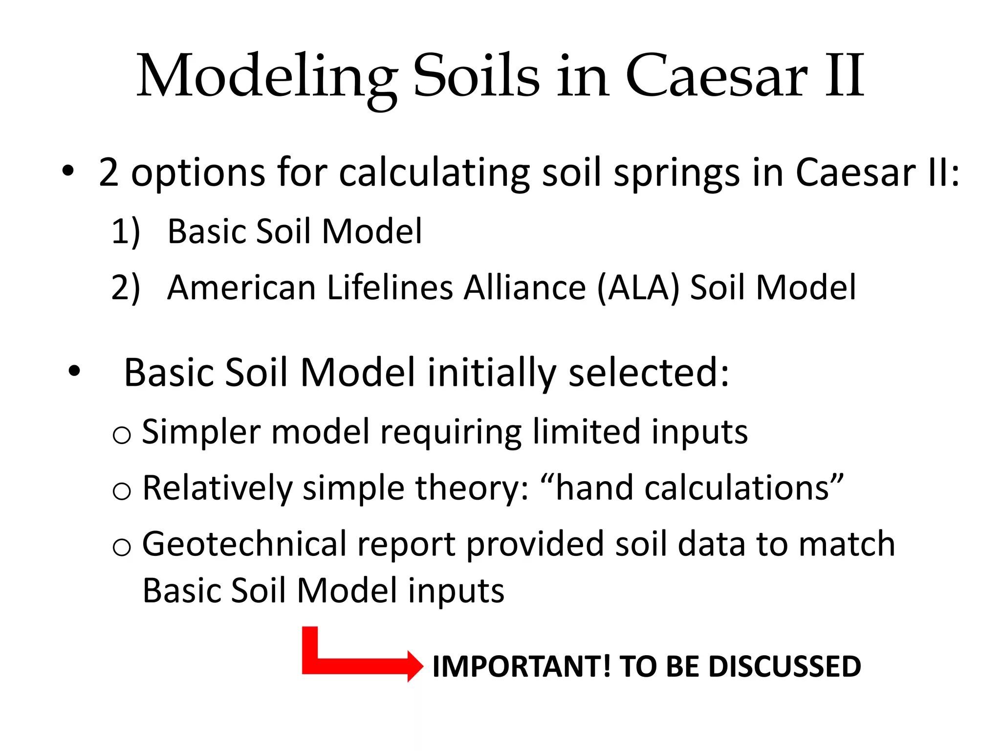
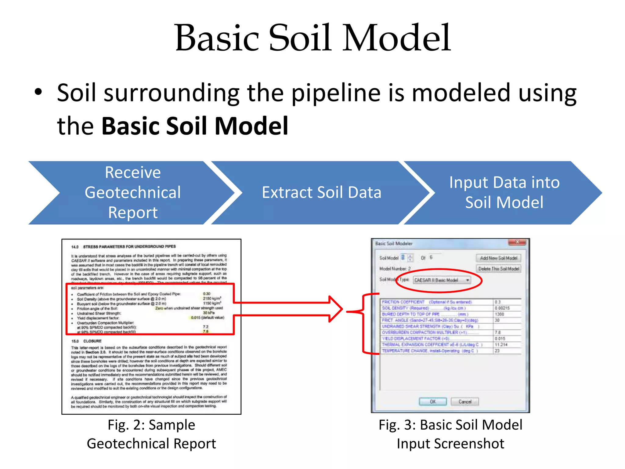
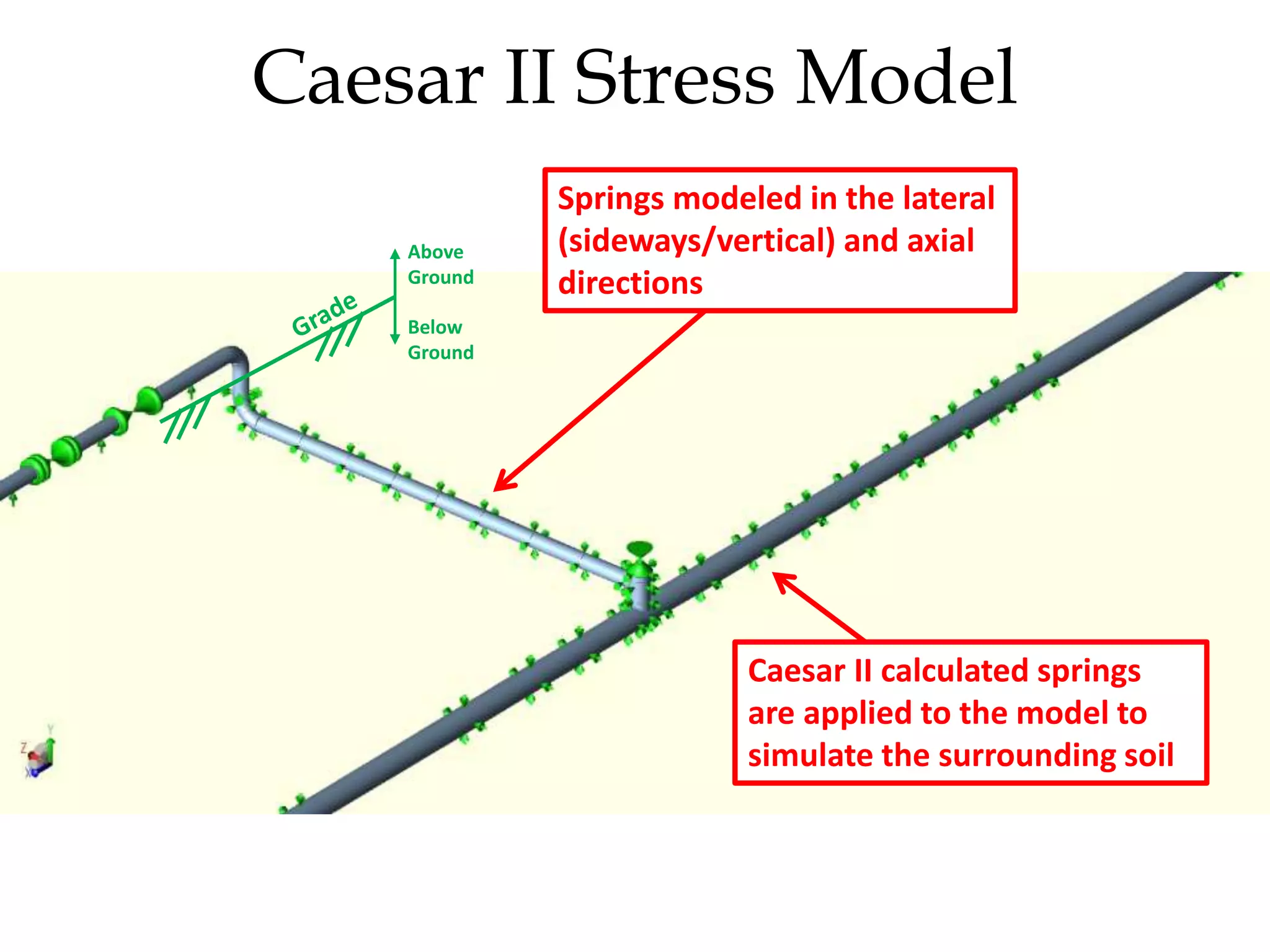
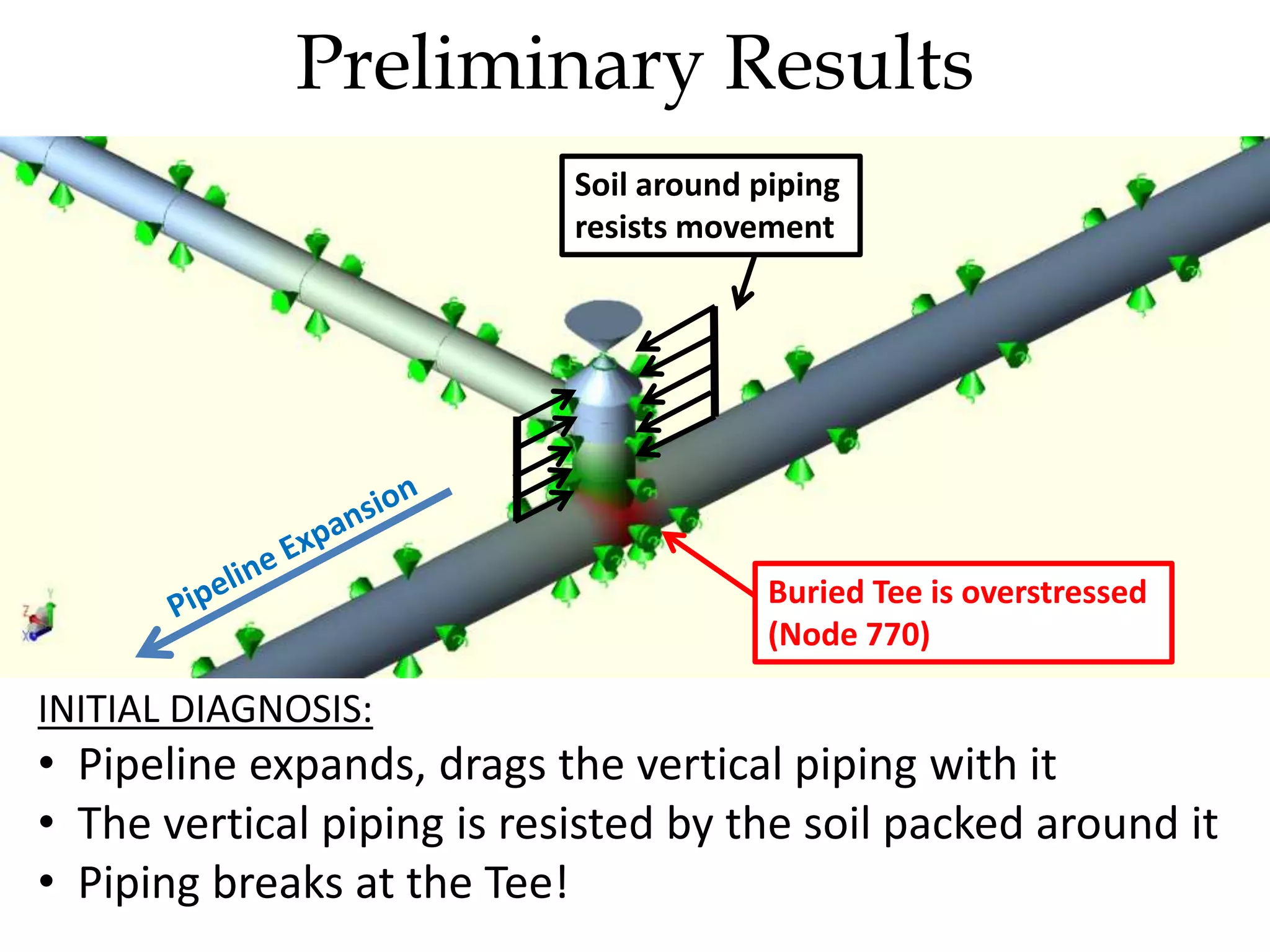
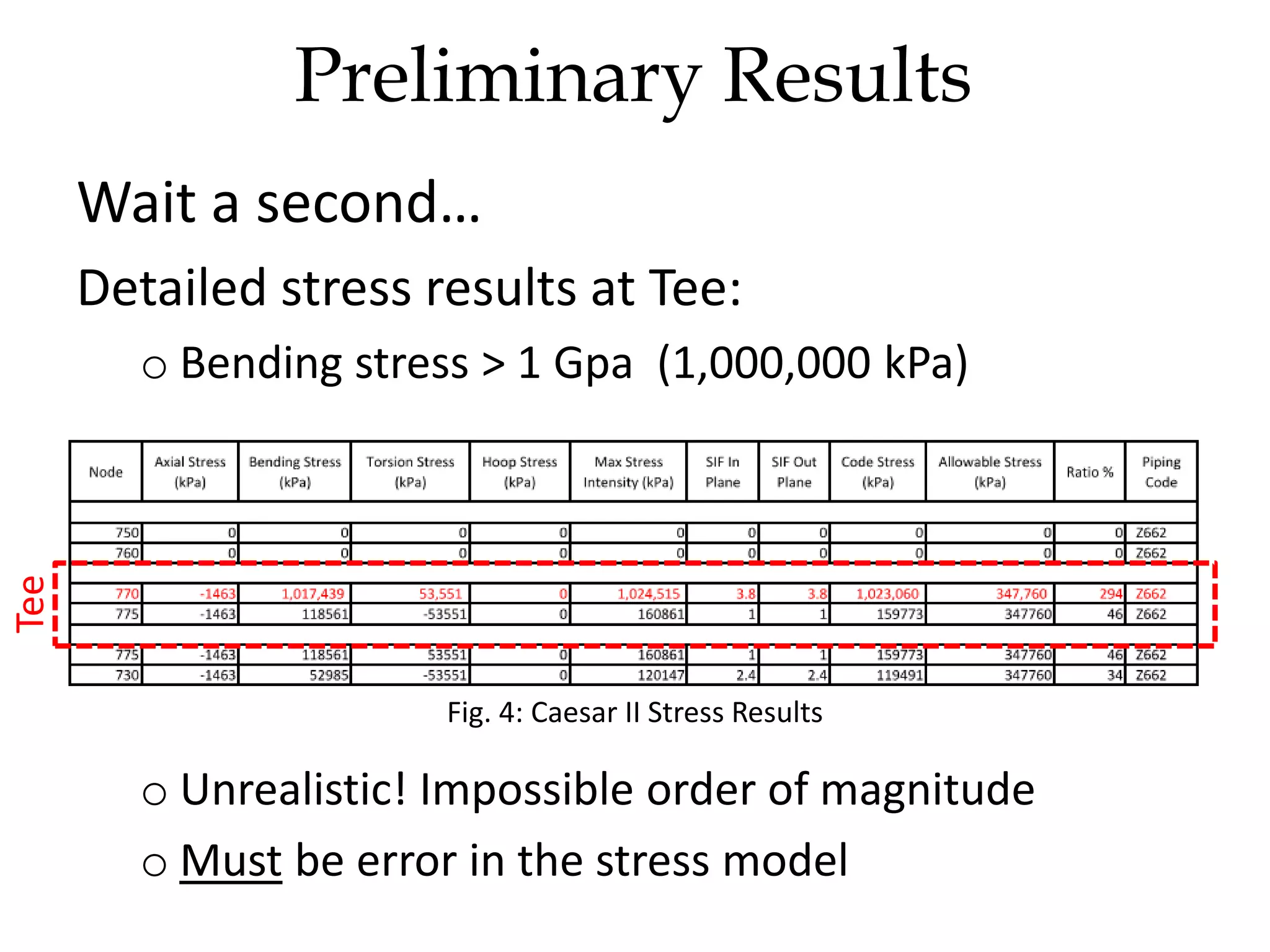
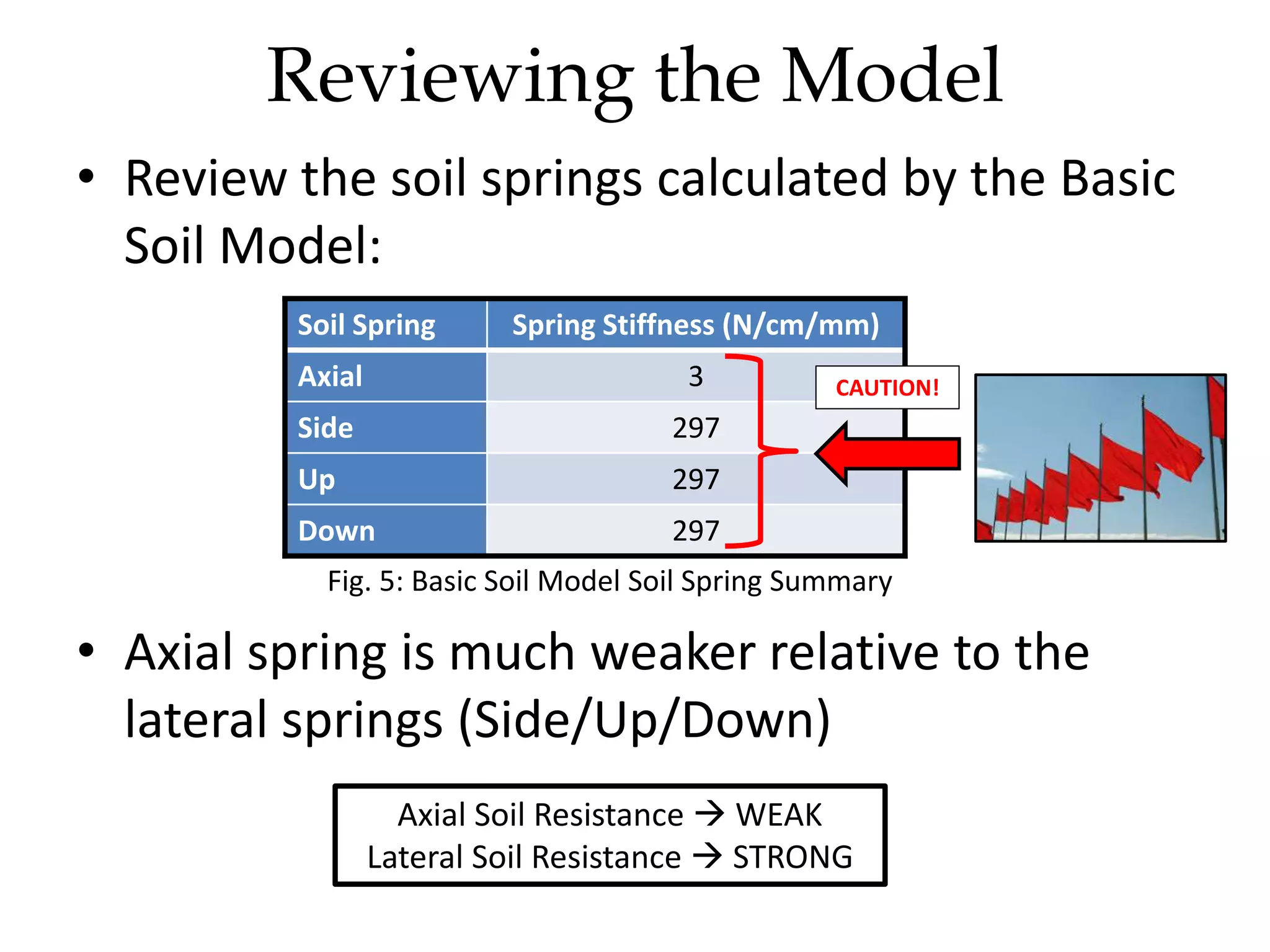
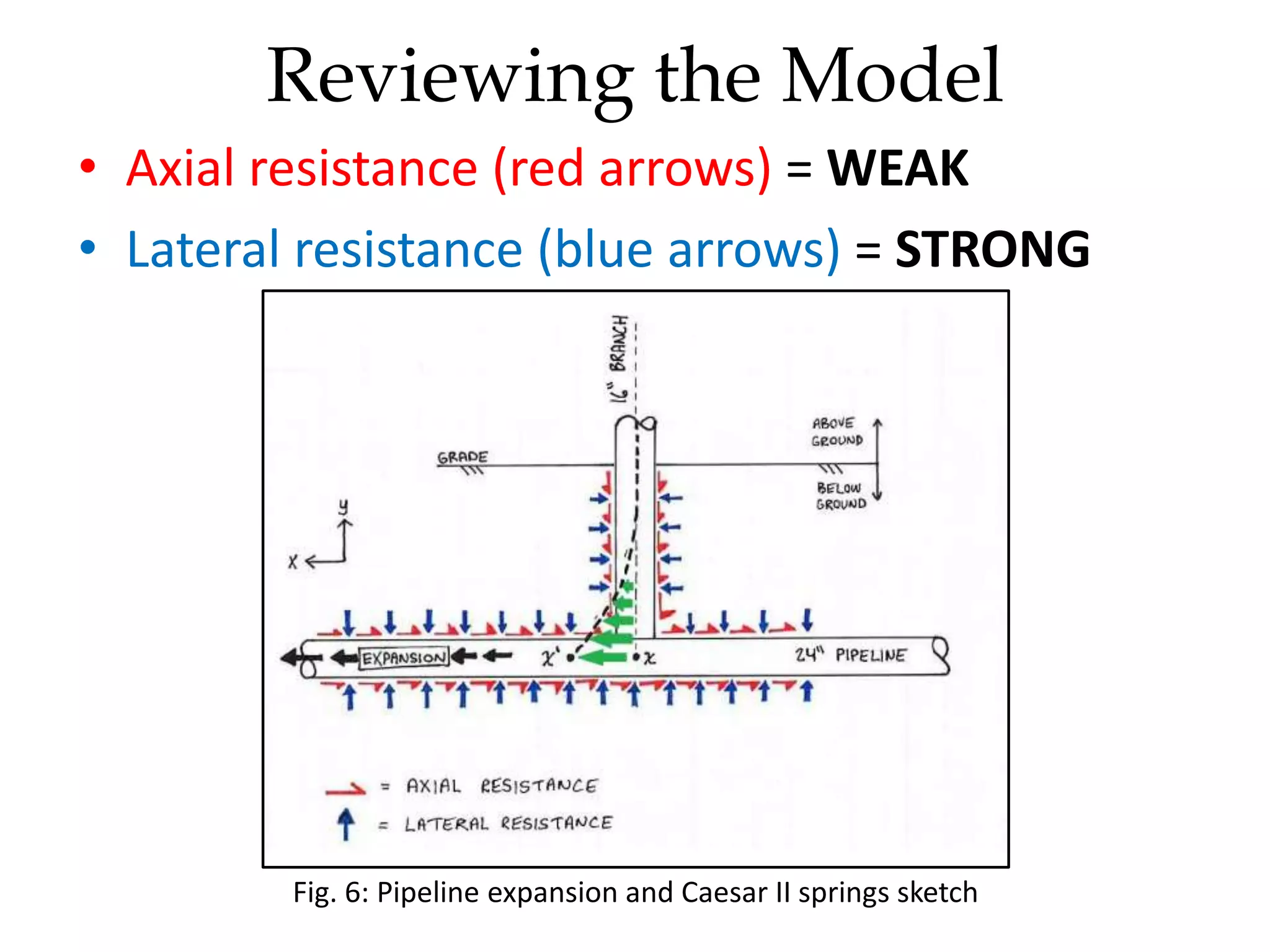
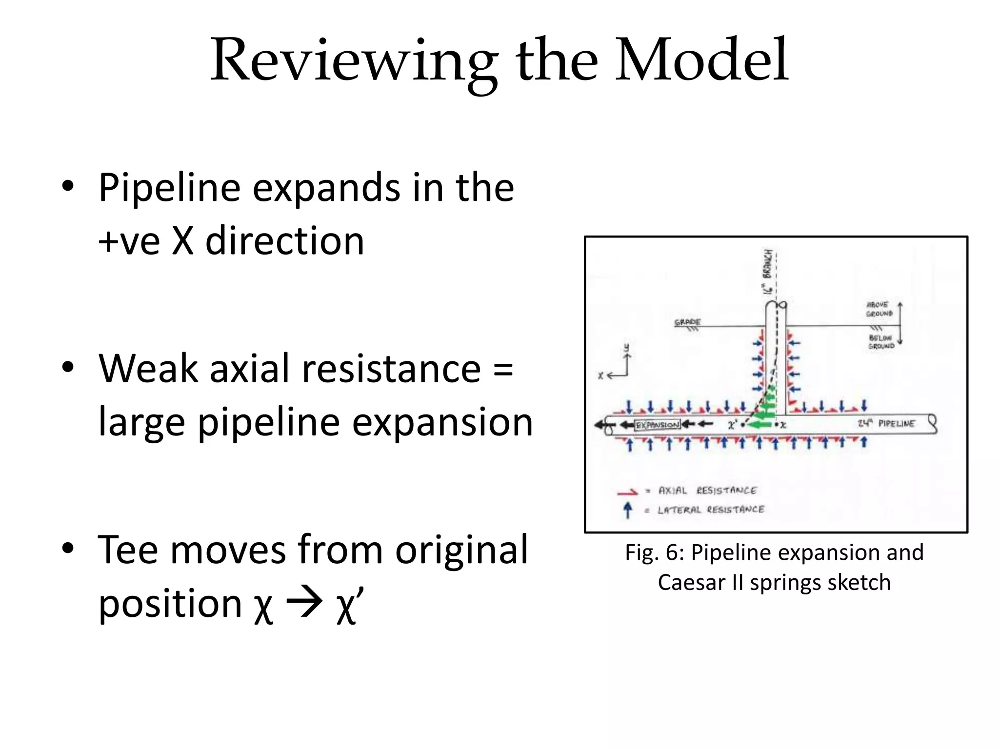
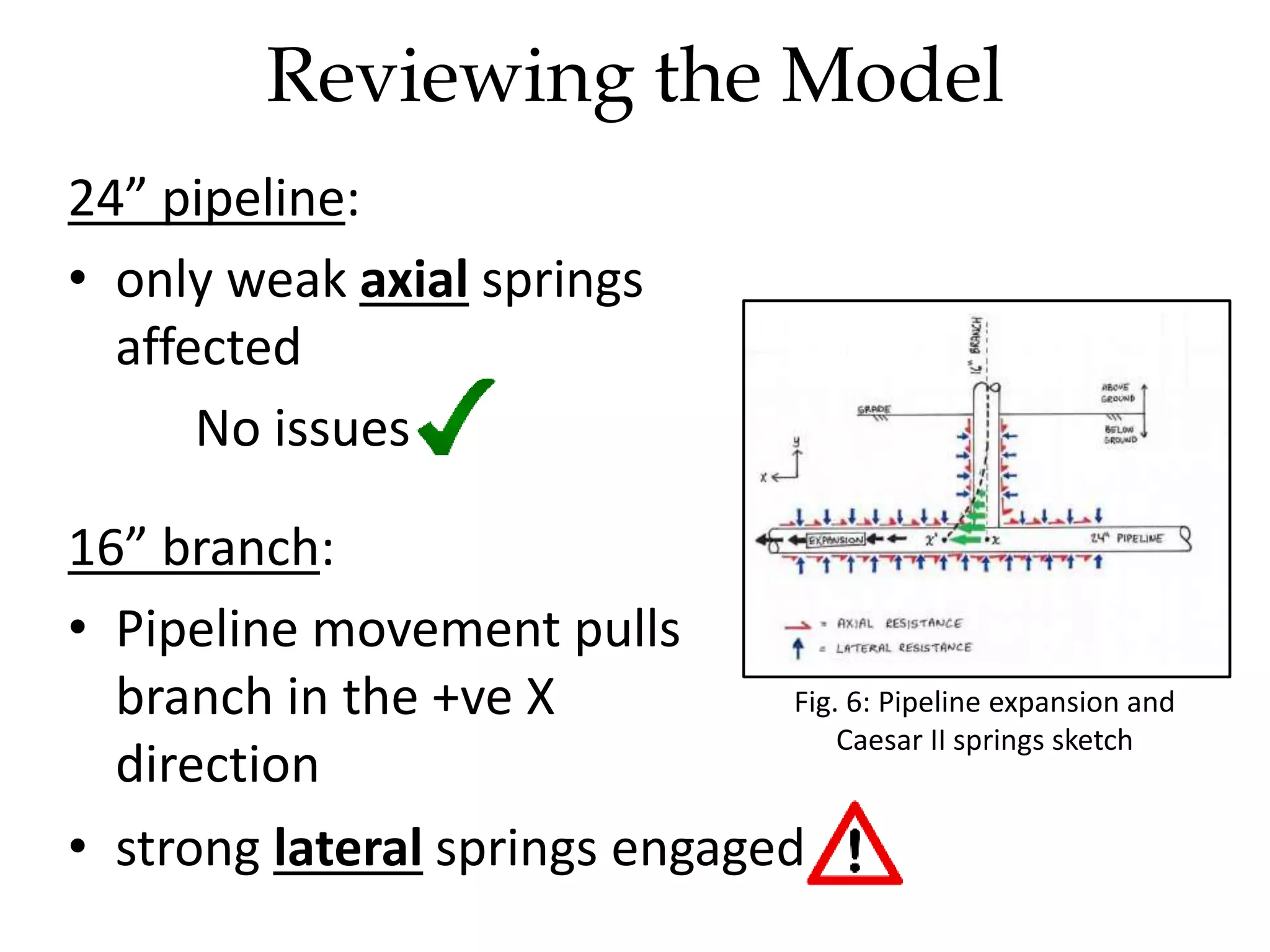
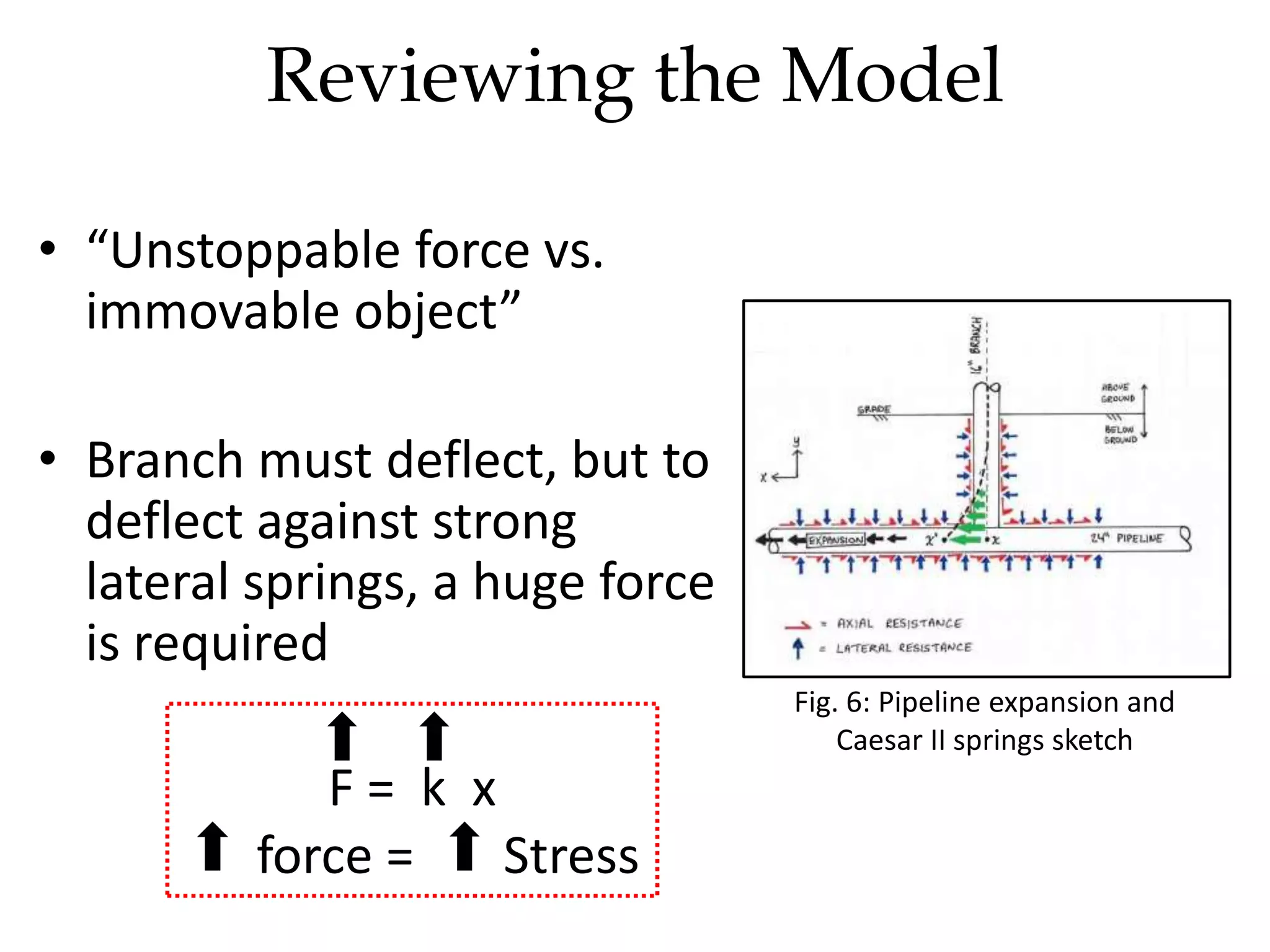
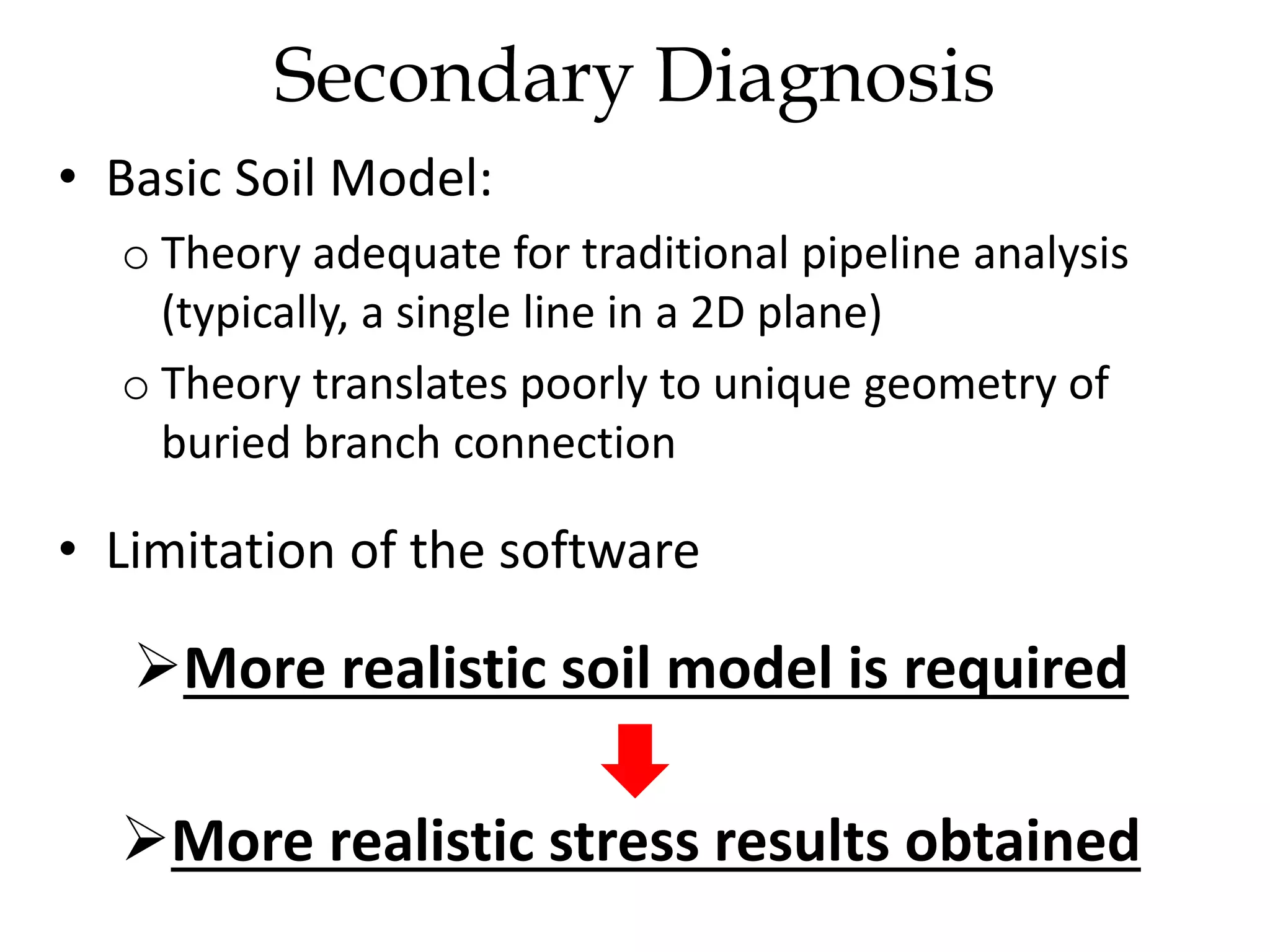
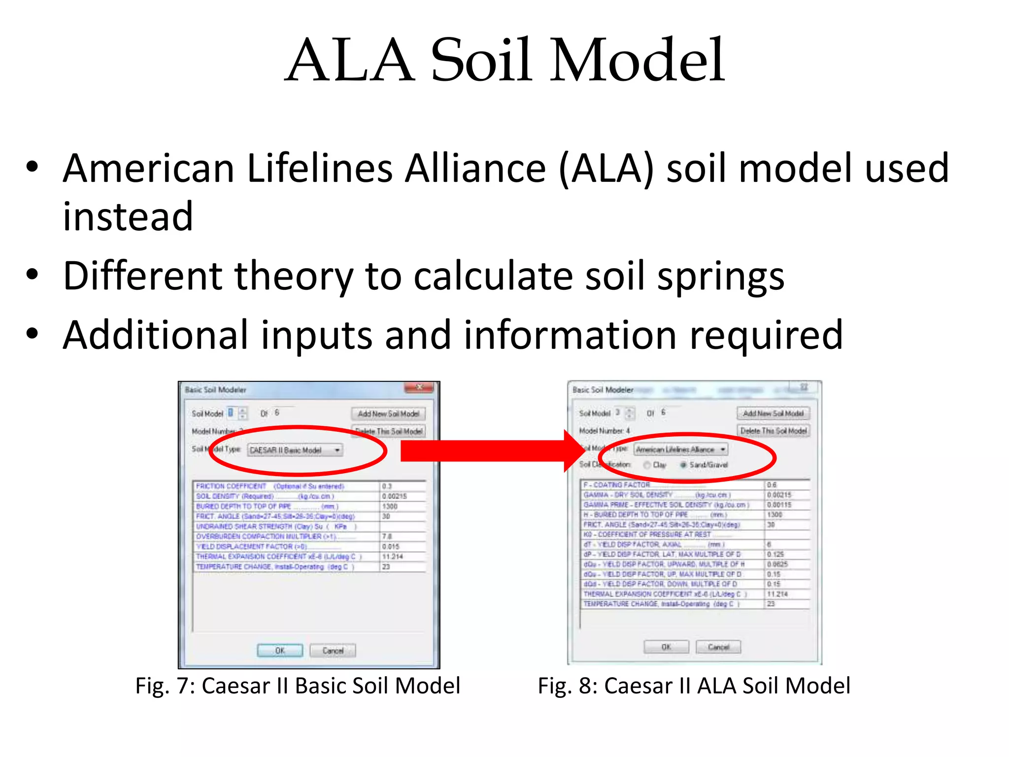
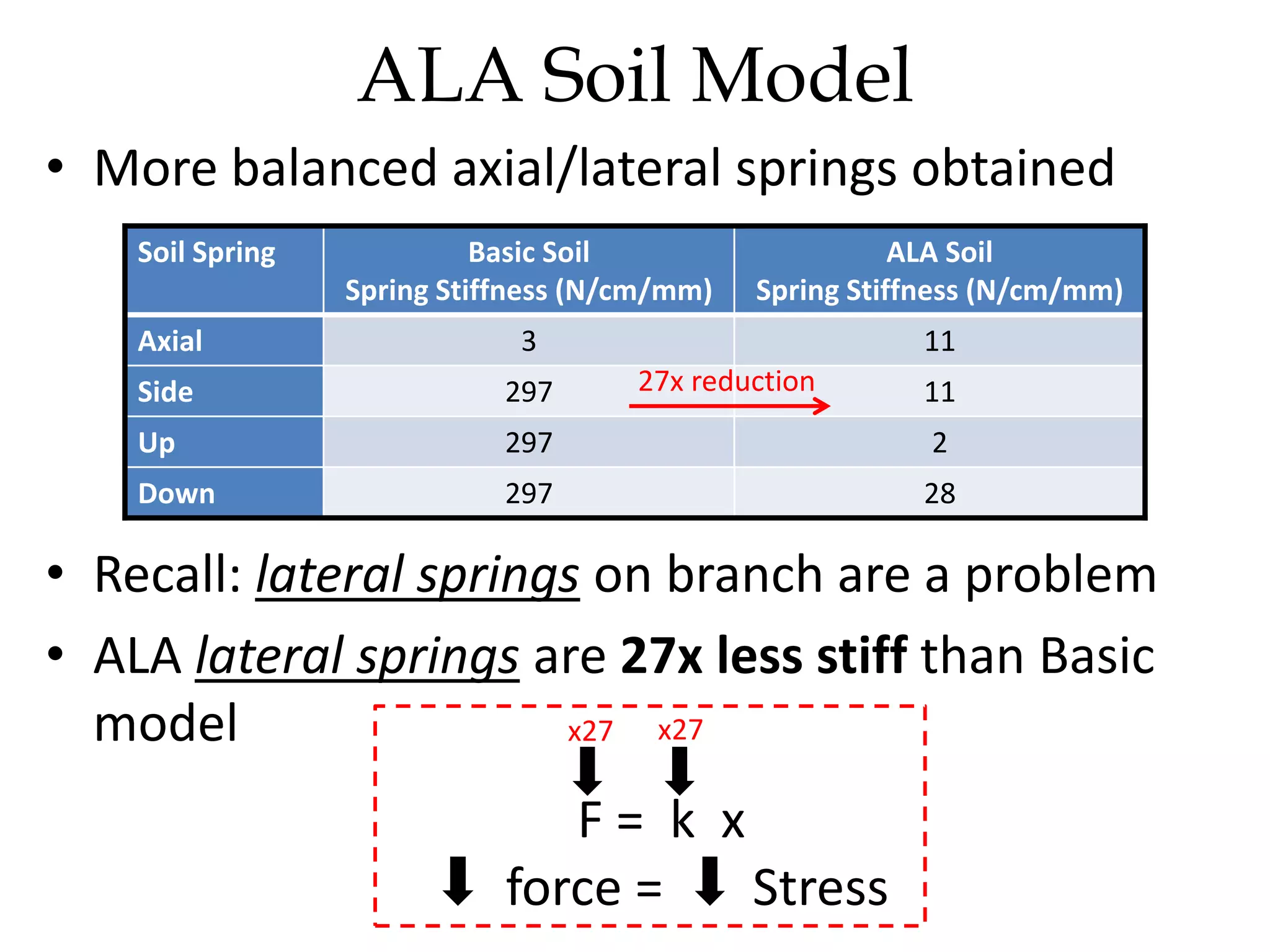
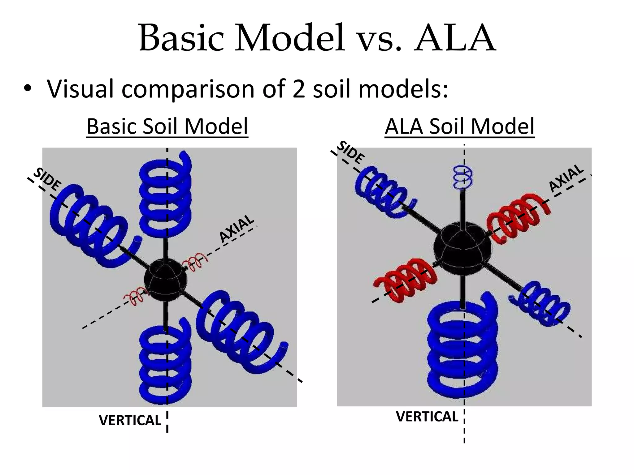
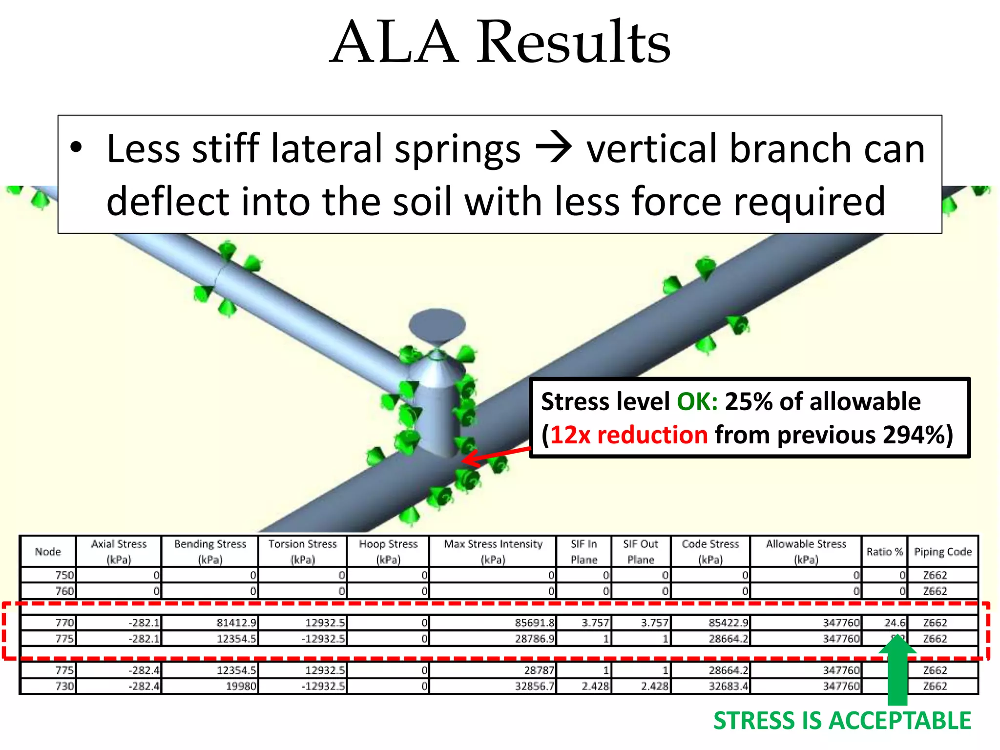
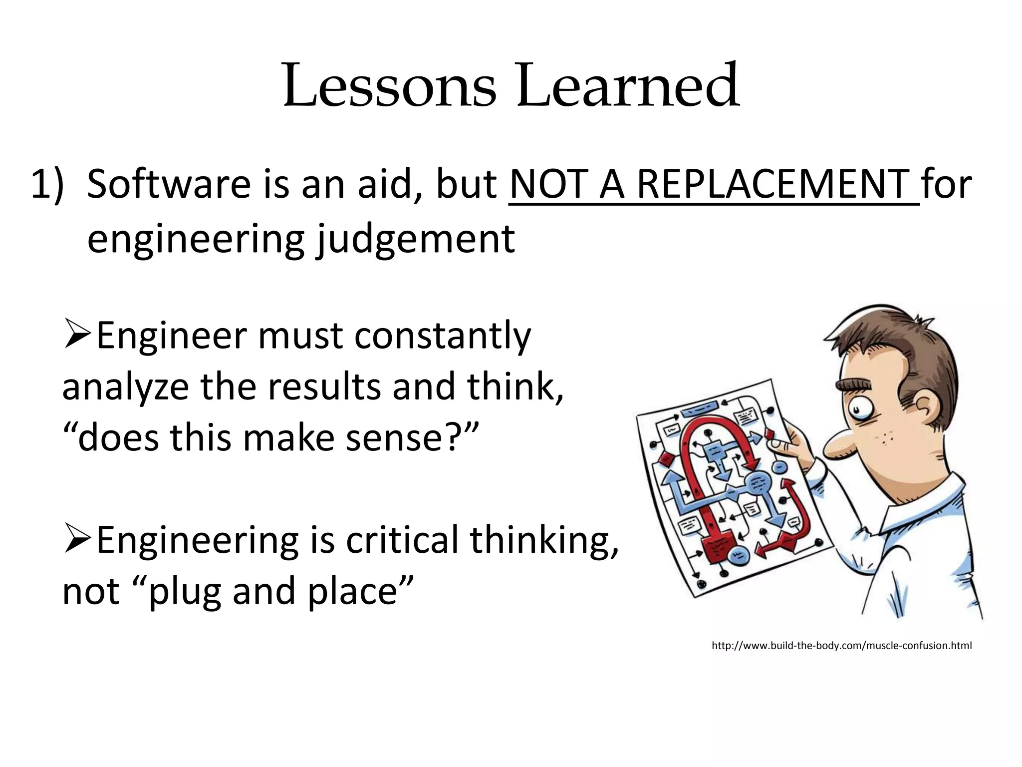
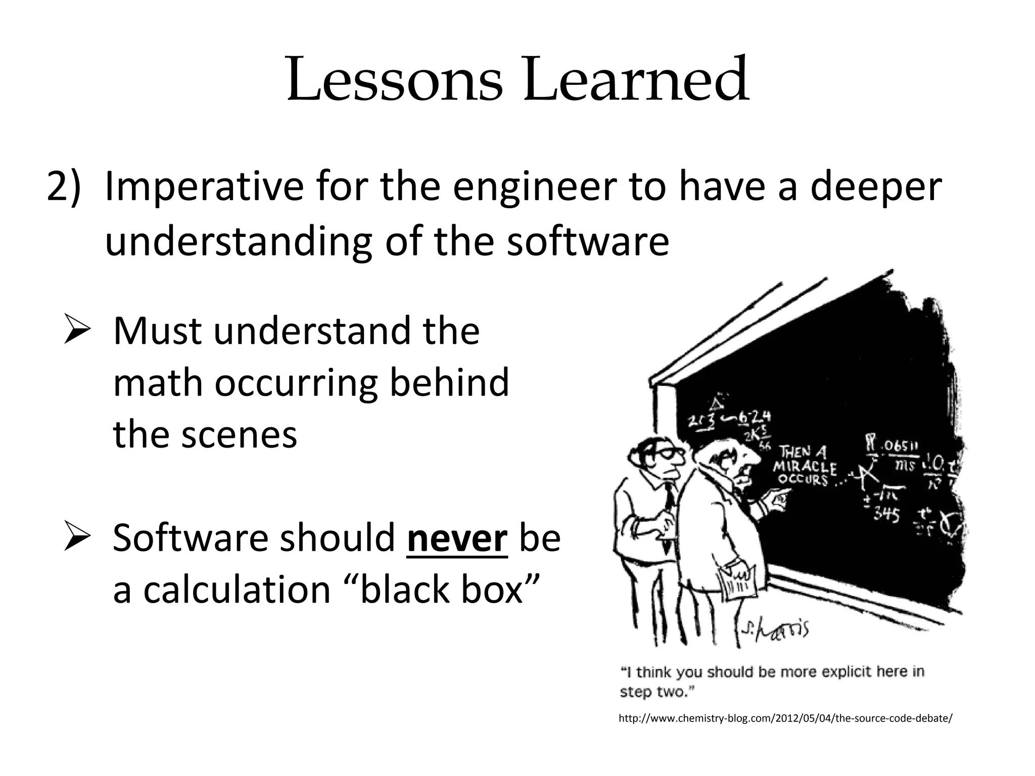
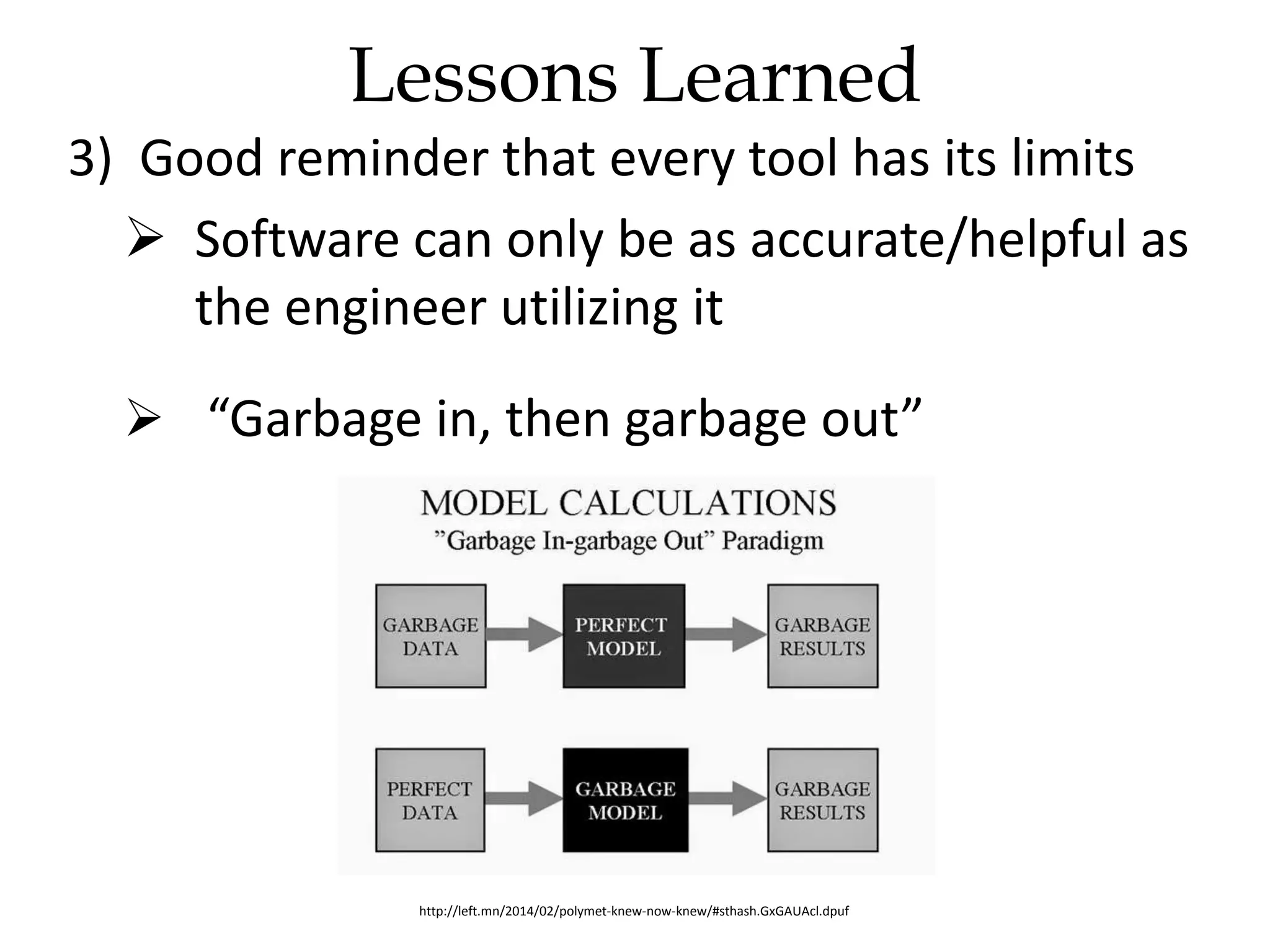
Understanding Piping Stress Analysis
Analyzing Buried Branch
Connections Using Caesar II
Zachary Swartz
June 10, 2015
Agenda
1) Introduction to Pipe Stress Analysis
2) Buried Tee Analysis
a) Preliminary Results
b) Determining the problem
3) Solution
4) Lessons Learned
Introduction
Pipe Stress Analysis:
• Computer modeling software simulates how
piping system will react under real-world
conditions:
Weight ǁ Temperature ǁ Pressure
• Piping will expand and contract in response to
these conditions
• Piping movement:
o creates stress in the pipe
o applies a force to the pipe restraints and connecting
equipment
• Stress levels are checked to ensure they remain
within allowable limits
• Forces on restraints/equipment are checked to
ensure they are not excessive
 Caesar II: Pipe stress analysis software
Introduction
New connection to
existing 24” pipeline
Above
Ground
Below
Ground
Above
Ground
Below
Ground
Caesar II Stress Model
Modeling Soils in Caesar II
• Caesar II simulates the soil surrounding the
pipeline using springs of varying stiffness
Fig. 1: Caesar II modeling the soil as springs
Stiff SpringWeak Spring
Dense SoilLoose Soil
• 2 options for calculating soil springs in Caesar II:
1) Basic Soil Model
2) American Lifelines Alliance (ALA) Soil Model
• Basic Soil Model initially selected:
o Simpler model requiring limited inputs
o Relatively simple theory: “hand calculations”
o Geotechnical report provided soil data to match
Basic Soil Model inputs
Modeling Soils in Caesar II
IMPORTANT! TO BE DISCUSSED
Basic Soil Model
• Soil surrounding the pipeline is modeled using
the Basic Soil Model
Fig. 2: Sample
Geotechnical Report
Fig. 3: Basic Soil Model
Input Screenshot
Receive
Geotechnical
Report
Extract Soil Data
Input Data into
Soil Model
Caesar II calculated springs
are applied to the model to
simulate the surrounding soil
Above
Ground
Below
Ground
Springs modeled in the lateral
(sideways/vertical) and axial
directions
Caesar II Stress Model
Preliminary Results
Buried Tee is overstressed
(Node 770)
INITIAL DIAGNOSIS:
• Pipeline expands, drags the vertical piping with it
• The vertical piping is resisted by the soil packed around it
• Piping breaks at the Tee!
Soil around piping
resists movement
Preliminary Results
There’s a stress problem!
Let’s fix it!
a) Make the Tee stronger!
b) Increase wall thickness!
c) Soft padding at the Tee!
$$$$$$$$$$
http://thesalesblog.com/wp-content/uploads/2013/11/Screen-Shot-2013-11-11-at-9.38.40-PM.png
On second thought, let me take another look and
get back to you…
Preliminary Results
Wait a second…
Detailed stress results at Tee:
o Bending stress > 1 Gpa (1,000,000 kPa)
o Unrealistic! Impossible order of magnitude
o Must be error in the stress model
Fig. 4: Caesar II Stress Results
Tee
Reviewing the Model
• Review the soil springs calculated by the Basic
Soil Model:
• Axial spring is much weaker relative to the
lateral springs (Side/Up/Down)
Axial Soil Resistance  WEAK
Lateral Soil Resistance  STRONG
Soil Spring Spring Stiffness (N/cm/mm)
Axial 3
Side 297
Up 297
Down 297
CAUTION!
Fig. 5: Basic Soil Model Soil Spring Summary
Fig. 6: Pipeline expansion and Caesar II springs sketch
Reviewing the Model
• Axial resistance (red arrows) = WEAK
• Lateral resistance (blue arrows) = STRONG
Fig. 6: Pipeline expansion and
Caesar II springs sketch
Reviewing the Model
• Pipeline expands in the
+ve X direction
• Weak axial resistance =
large pipeline expansion
• Tee moves from original
position χ  χ’
24” pipeline:
• only weak axial springs
affected
No issues
16” branch:
• Pipeline movement pulls
branch in the +ve X
direction
Reviewing the Model
Fig. 6: Pipeline expansion and
Caesar II springs sketch
• strong lateral springs engaged
• “Unstoppable force vs.
immovable object”
• Branch must deflect, but to
deflect against strong
lateral springs, a huge force
is required
F = k x
force = Stress
Reviewing the Model
Fig. 6: Pipeline expansion and
Caesar II springs sketch
• Basic Soil Model:
o Theory adequate for traditional pipeline analysis
(typically, a single line in a 2D plane)
o Theory translates poorly to unique geometry of
buried branch connection
• Limitation of the software
More realistic soil model is required
More realistic stress results obtained
Secondary Diagnosis
Fig. 7: Caesar II Basic Soil Model Fig. 8: Caesar II ALA Soil Model
• American Lifelines Alliance (ALA) soil model used
instead
• Different theory to calculate soil springs
• Additional inputs and information required
ALA Soil Model
• More balanced axial/lateral springs obtained
• Recall: lateral springs on branch are a problem
• ALA lateral springs are 27x less stiff than Basic
model
ALA Soil Model
Soil Spring Basic Soil
Spring Stiffness (N/cm/mm)
ALA Soil
Spring Stiffness (N/cm/mm)
Axial 3 11
Side 297 11
Up 297 2
Down 297 28
27x reduction
F = k x
force = Stress
x27x27
• Visual comparison of 2 soil models:
Basic Soil Model ALA Soil Model
Basic Model vs. ALA
VERTICAL VERTICAL
Stress level OK: 25% of allowable
(12x reduction from previous 294%)
• Less stiff lateral springs  vertical branch can
deflect into the soil with less force required
STRESS IS ACCEPTABLE
ALA Results
https://encrypted-tbn2.gstatic.com/images?q=tbn:ANd9GcRskVcSS2Z_SyCYae9zAgQtspvH8dVxPtxkIXnEmdFotzPicEEa
• Caesar II Basic Soil Model was initially used:
1) Simpler model
2) Easy to procure and input data for Basic Model
3) Geotech report provided soil inputs in Basic
Model format
• Simple communication issue (or lack thereof)
Client can provide us inputs for either format,
we just have to ask!
Conclusion
• ALA Soil Model used after further examination
More realistic soil spring values
• Costly (potentially impossible) modifications were
avoided
Conclusion
Lessons Learned
1) Software is an aid, but NOT A REPLACEMENT for
engineering judgement
Engineer must constantly
analyze the results and think,
“does this make sense?”
Engineering is critical thinking,
not “plug and place”
http://www.build-the-body.com/muscle-confusion.html
2) Imperative for the engineer to have a deeper
understanding of the software
 Must understand the
math occurring behind
the scenes
 Software should never be
a calculation “black box”
http://www.chemistry-blog.com/2012/05/04/the-source-code-debate/
Lessons Learned
3) Good reminder that every tool has its limits
 Software can only be as accurate/helpful as
the engineer utilizing it
 “Garbage in, then garbage out”
http://left.mn/2014/02/polymet-knew-now-knew/#sthash.GxGAUAcl.dpuf
Lessons Learned

Understanding Stress Analysis Topics

  • 1.
    Understanding Piping StressAnalysis Analyzing Buried Branch Connections Using Caesar II Zachary Swartz June 10, 2015
  • 2.
    Agenda 1) Introduction toPipe Stress Analysis 2) Buried Tee Analysis a) Preliminary Results b) Determining the problem 3) Solution 4) Lessons Learned
  • 3.
    Introduction Pipe Stress Analysis: •Computer modeling software simulates how piping system will react under real-world conditions: Weight ǁ Temperature ǁ Pressure • Piping will expand and contract in response to these conditions
  • 4.
    • Piping movement: ocreates stress in the pipe o applies a force to the pipe restraints and connecting equipment • Stress levels are checked to ensure they remain within allowable limits • Forces on restraints/equipment are checked to ensure they are not excessive  Caesar II: Pipe stress analysis software Introduction
  • 5.
    New connection to existing24” pipeline Above Ground Below Ground Above Ground Below Ground Caesar II Stress Model
  • 6.
    Modeling Soils inCaesar II • Caesar II simulates the soil surrounding the pipeline using springs of varying stiffness Fig. 1: Caesar II modeling the soil as springs Stiff SpringWeak Spring Dense SoilLoose Soil
  • 7.
    • 2 optionsfor calculating soil springs in Caesar II: 1) Basic Soil Model 2) American Lifelines Alliance (ALA) Soil Model • Basic Soil Model initially selected: o Simpler model requiring limited inputs o Relatively simple theory: “hand calculations” o Geotechnical report provided soil data to match Basic Soil Model inputs Modeling Soils in Caesar II IMPORTANT! TO BE DISCUSSED
  • 8.
    Basic Soil Model •Soil surrounding the pipeline is modeled using the Basic Soil Model Fig. 2: Sample Geotechnical Report Fig. 3: Basic Soil Model Input Screenshot Receive Geotechnical Report Extract Soil Data Input Data into Soil Model
  • 9.
    Caesar II calculatedsprings are applied to the model to simulate the surrounding soil Above Ground Below Ground Springs modeled in the lateral (sideways/vertical) and axial directions Caesar II Stress Model
  • 10.
    Preliminary Results Buried Teeis overstressed (Node 770) INITIAL DIAGNOSIS: • Pipeline expands, drags the vertical piping with it • The vertical piping is resisted by the soil packed around it • Piping breaks at the Tee! Soil around piping resists movement
  • 11.
    Preliminary Results There’s astress problem! Let’s fix it! a) Make the Tee stronger! b) Increase wall thickness! c) Soft padding at the Tee! $$$$$$$$$$
  • 12.
  • 13.
    Preliminary Results Wait asecond… Detailed stress results at Tee: o Bending stress > 1 Gpa (1,000,000 kPa) o Unrealistic! Impossible order of magnitude o Must be error in the stress model Fig. 4: Caesar II Stress Results Tee
  • 14.
    Reviewing the Model •Review the soil springs calculated by the Basic Soil Model: • Axial spring is much weaker relative to the lateral springs (Side/Up/Down) Axial Soil Resistance  WEAK Lateral Soil Resistance  STRONG Soil Spring Spring Stiffness (N/cm/mm) Axial 3 Side 297 Up 297 Down 297 CAUTION! Fig. 5: Basic Soil Model Soil Spring Summary
  • 15.
    Fig. 6: Pipelineexpansion and Caesar II springs sketch Reviewing the Model • Axial resistance (red arrows) = WEAK • Lateral resistance (blue arrows) = STRONG
  • 16.
    Fig. 6: Pipelineexpansion and Caesar II springs sketch Reviewing the Model • Pipeline expands in the +ve X direction • Weak axial resistance = large pipeline expansion • Tee moves from original position χ  χ’
  • 17.
    24” pipeline: • onlyweak axial springs affected No issues 16” branch: • Pipeline movement pulls branch in the +ve X direction Reviewing the Model Fig. 6: Pipeline expansion and Caesar II springs sketch • strong lateral springs engaged
  • 18.
    • “Unstoppable forcevs. immovable object” • Branch must deflect, but to deflect against strong lateral springs, a huge force is required F = k x force = Stress Reviewing the Model Fig. 6: Pipeline expansion and Caesar II springs sketch
  • 19.
    • Basic SoilModel: o Theory adequate for traditional pipeline analysis (typically, a single line in a 2D plane) o Theory translates poorly to unique geometry of buried branch connection • Limitation of the software More realistic soil model is required More realistic stress results obtained Secondary Diagnosis
  • 20.
    Fig. 7: CaesarII Basic Soil Model Fig. 8: Caesar II ALA Soil Model • American Lifelines Alliance (ALA) soil model used instead • Different theory to calculate soil springs • Additional inputs and information required ALA Soil Model
  • 21.
    • More balancedaxial/lateral springs obtained • Recall: lateral springs on branch are a problem • ALA lateral springs are 27x less stiff than Basic model ALA Soil Model Soil Spring Basic Soil Spring Stiffness (N/cm/mm) ALA Soil Spring Stiffness (N/cm/mm) Axial 3 11 Side 297 11 Up 297 2 Down 297 28 27x reduction F = k x force = Stress x27x27
  • 22.
    • Visual comparisonof 2 soil models: Basic Soil Model ALA Soil Model Basic Model vs. ALA VERTICAL VERTICAL
  • 23.
    Stress level OK:25% of allowable (12x reduction from previous 294%) • Less stiff lateral springs  vertical branch can deflect into the soil with less force required STRESS IS ACCEPTABLE ALA Results
  • 24.
  • 25.
    • Caesar IIBasic Soil Model was initially used: 1) Simpler model 2) Easy to procure and input data for Basic Model 3) Geotech report provided soil inputs in Basic Model format • Simple communication issue (or lack thereof) Client can provide us inputs for either format, we just have to ask! Conclusion
  • 26.
    • ALA SoilModel used after further examination More realistic soil spring values • Costly (potentially impossible) modifications were avoided Conclusion
  • 27.
    Lessons Learned 1) Softwareis an aid, but NOT A REPLACEMENT for engineering judgement Engineer must constantly analyze the results and think, “does this make sense?” Engineering is critical thinking, not “plug and place” http://www.build-the-body.com/muscle-confusion.html
  • 28.
    2) Imperative forthe engineer to have a deeper understanding of the software  Must understand the math occurring behind the scenes  Software should never be a calculation “black box” http://www.chemistry-blog.com/2012/05/04/the-source-code-debate/ Lessons Learned
  • 29.
    3) Good reminderthat every tool has its limits  Software can only be as accurate/helpful as the engineer utilizing it  “Garbage in, then garbage out” http://left.mn/2014/02/polymet-knew-now-knew/#sthash.GxGAUAcl.dpuf Lessons Learned