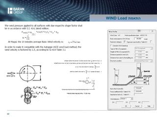
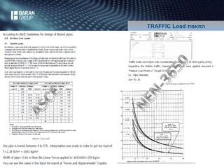
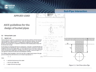
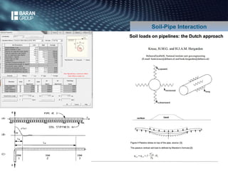
Downloaded 733 times

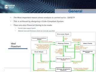
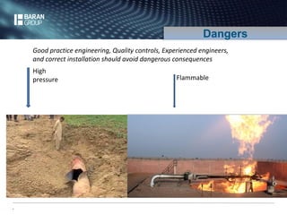
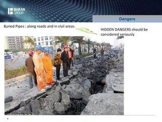
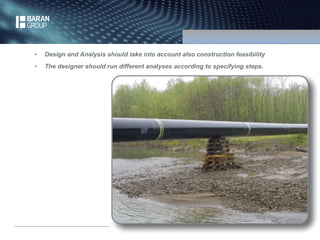


The document outlines stress analysis techniques for piping systems, emphasizing safety and financial benefits through proper design and material specifications. It discusses various loads, standards, and the importance of experienced engineering to avoid catastrophic failures, focusing on sustained, pressure, and seismic stresses. Recommendations include appropriate pipe thickness calculations and the necessity of accurate construction feasibility assessments.


![[Point] pipe stress analysis by computer-caesar ii](https://cdn.slidesharecdn.com/ss_thumbnails/point-pipestressanalysisbycomputer-caesarii-150407122607-conversion-gate01-thumbnail.jpg?width=640&height=640&fit=bounds)


