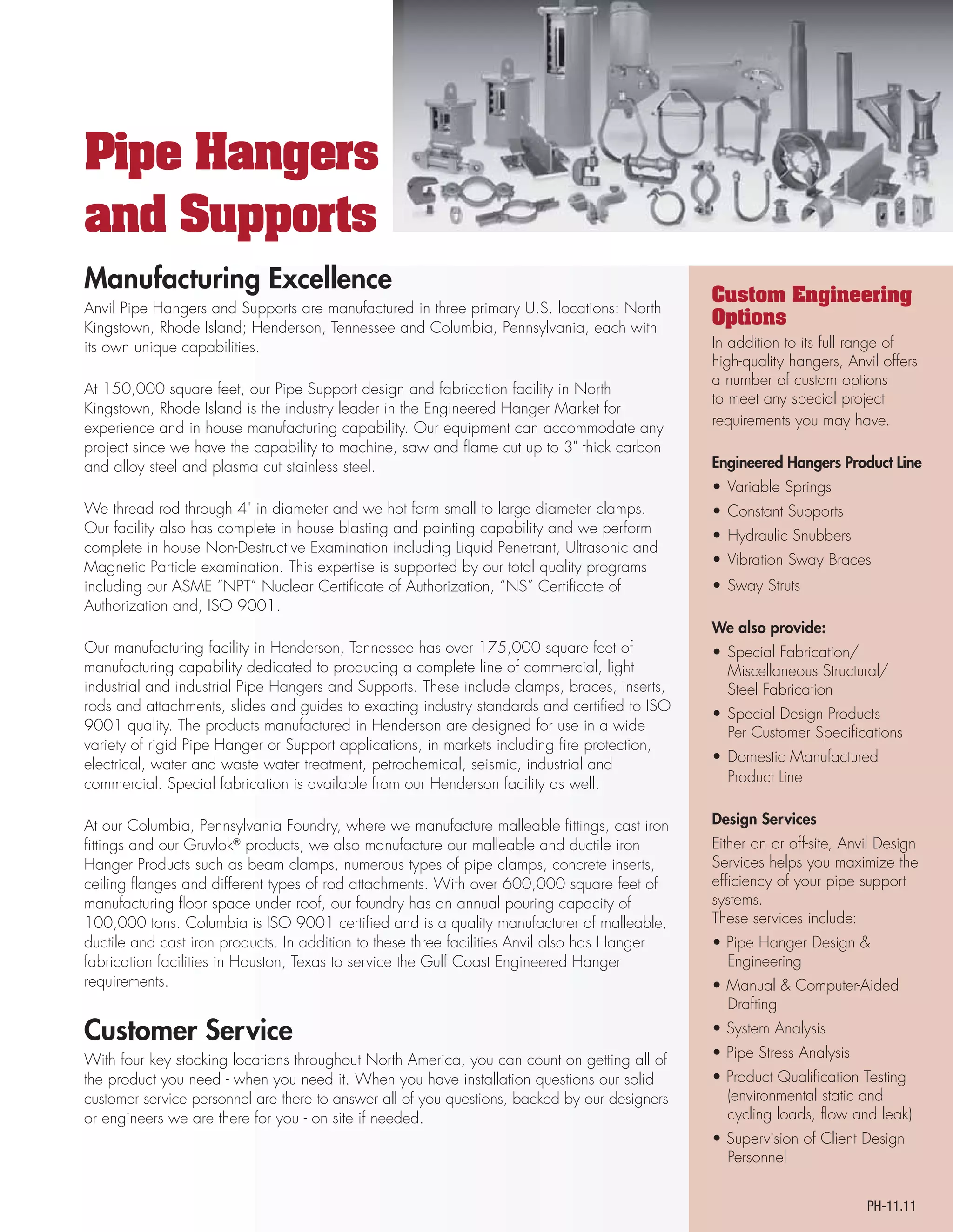
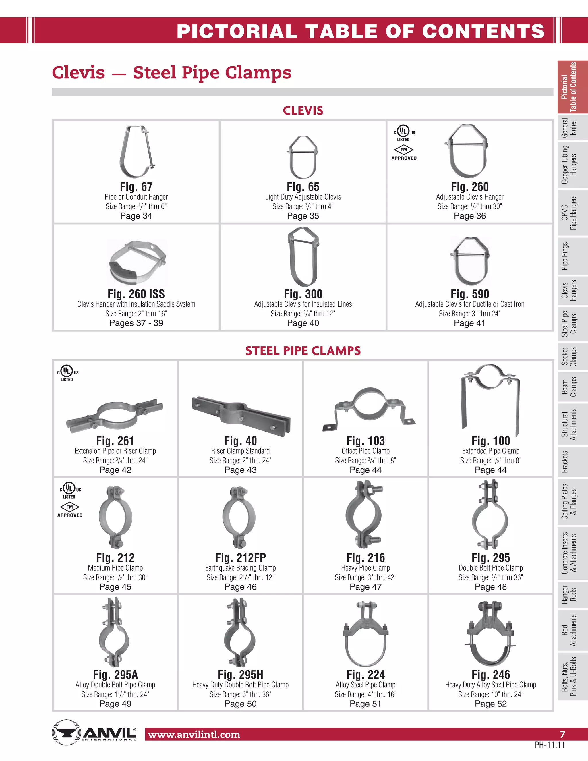
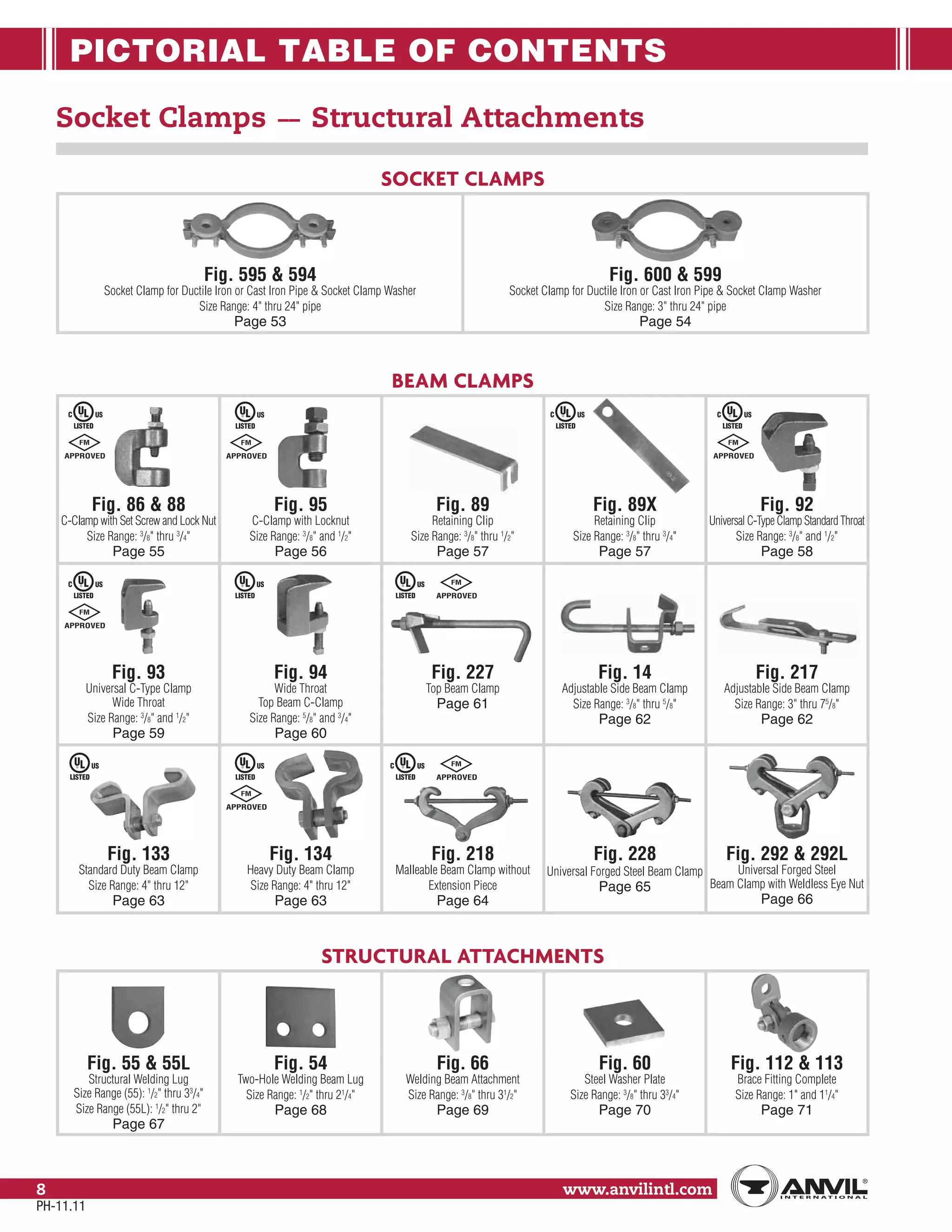
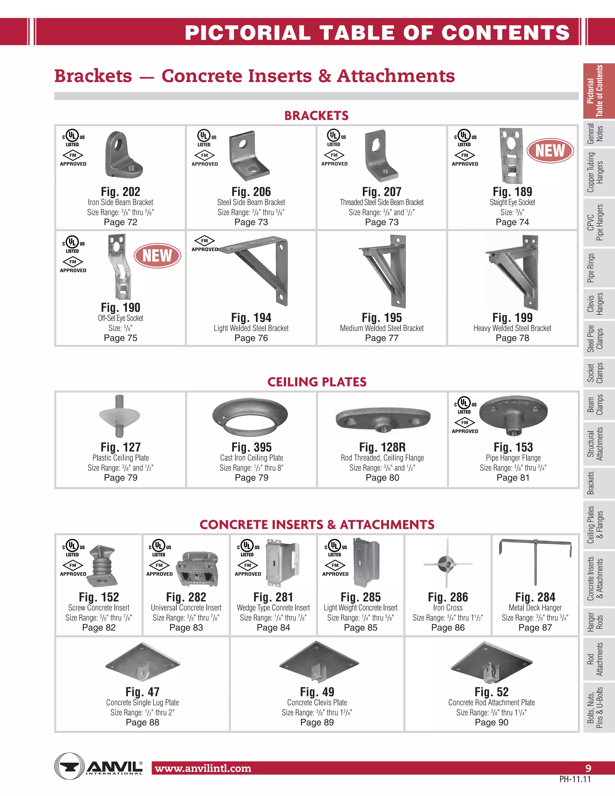
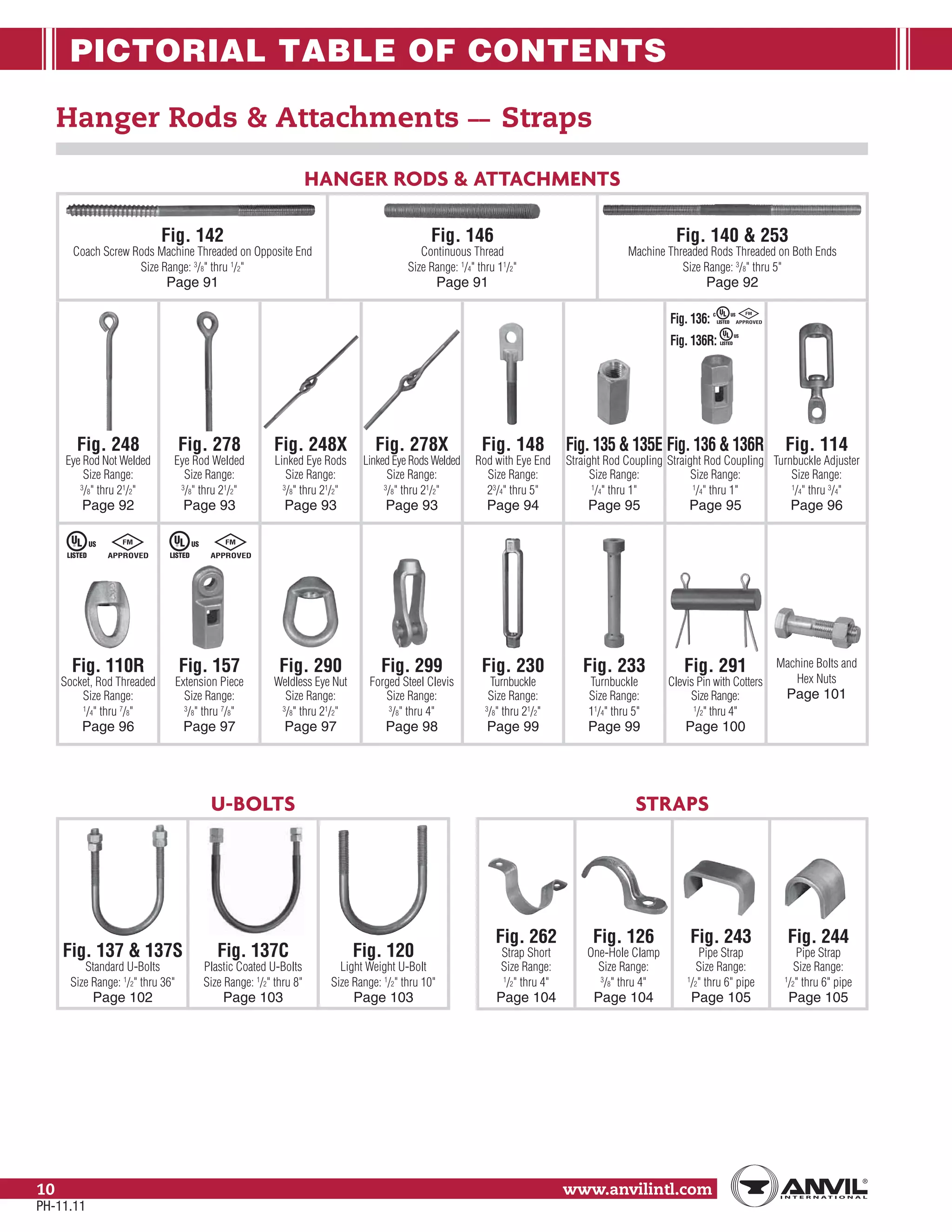
This document provides information on pipe hangers and supports manufactured by Anvil. It summarizes Anvil's manufacturing facilities, quality programs, and product lines. The company has manufacturing locations in North Kingstown, Rhode Island, Henderson, Tennessee, and Columbia, Pennsylvania that produce a comprehensive line of pipe hangers and supports using various materials and fabrication methods. Anvil prides itself on responsive customer service and delivering product solutions.
This document provides information on flange management including piping specifications, flanges, gaskets, and flange bolting. It discusses piping specifications, commonly used materials, pipe sizing standards, flange types, standards, pressure and temperature ratings, specifications, identification, installation guidelines, and gasket types. It emphasizes the importance of following piping specifications and using the correct materials for flanges and gaskets according to the service conditions.
This document provides guidelines for the design of steel stacks. It covers terminology, loading considerations, materials, structural design, construction, inspection, maintenance and painting. Key points include:
1. Stack design is complex due to susceptibility to wind and seismic vibrations, as well as corrosion. EPA regulations also emphasize mechanical design.
2. Stacks can be free standing, multi-flue, base supported and braced, or base supported and guyed. Vertical and lateral supports are considered.
3. Stacks may be laterally supported by other structures like towers. Structural interaction must be considered in analysis. Braced stacks require smaller foundations.
This presentation will cover pipe support design, 3D modeling, Finite Element Analysis, special stress and thermal cases, along with the unique cases that brought on new pipe support designs. Increase your understanding of the value-added services that are offered by PT&P.
Anvil is a leading manufacturer of pipe hangers and supports with a long history of design excellence and quality products. They have state-of-the-art manufacturing facilities in the US that produce a wide range of hangers, clamps, braces and other products to support pipes. Anvil offers comprehensive design services and stocks products globally to support customers in industries like power, oil/gas, marine, and more.
The document illustrates different types of pressure vessels including a horizontal drum on saddle supports, a vertical vessel with leg support, a vertical vessel with lug support, a column, and a reactor. Each illustration shows the main components of the vessel including the shell, heads, supports, nozzles, and internal structures like catalyst beds.
This document provides an overview and revision details for IS 6533 (Part 2) : 1989, the Indian Standard Code of Practice for Design and Construction of Steel Chimney, Part 2 Structural Aspect. It discusses the scope of the standard, references other relevant standards, outlines key terminology, and specifies materials requirements. The standard was revised to bifurcate mechanical and structural aspects into two parts, include dynamic wind effects as a design check, and make the code more concise by removing commonly known formulae and calculation steps.
This document provides procedures for the fabrication, installation, and erection of piping. It outlines responsibilities for construction management, engineering, quality control, and health and safety. It also describes procedures for receiving and storing materials, pre-fabrication including cutting, beveling and fit-up, welding, testing, and installation of underground and erected piping. Attachments include job safety analyses, work flows, lifting plans, and inspection forms. The goal is to ensure compliance with contractual and health, safety, and environmental requirements for piping work.
Slip on flange welding according TO asme b31.3Amr Soliman
This document discusses slip-on flange welding according to ASME B31.3-2016 standards. It explains that slip-on flange welding uses an equal fillet weld and the weld size is measured by the leg length using a welding gauge. It provides equations for calculating the fillet weld size on both the flange face side and hub end side based on the pipe wall thickness and hub thickness. A practical example is given to demonstrate calculating the weld sizes for a sample stainless steel flange.
This manual covers the basic guidelines and minimum requirements for
periodic inspection of heat exchangers used in petroleum refinery.
Locations to be inspected, inspection tools, frequency of inspection &
testing, locations prone to deterioration and causes, corrosion
mitigation, inspection and testing procedures have been specified in
the manual.
Documentation of observations & history of heat exchangers,
inspection checklist and recommended practices have also been
included.
Heat exchanging equipment is used for heating or cooling a fluid.
Individual heat transfer equipment is named as per its function.
Cooler
A cooler cools the process fluid, using water or air, with no change of
phase.
Chiller
A chiller uses a refrigerant to cool process fluid to a temperature below
that obtainable with water.
Condenser
A condenser condenses a vapour or mixture of vapours using water or
air.
Exchanger
An exchanger performs two functions in that it heats a cold process
fluid by recovering heat from a hot fluid, which it cools. None of the
transferred heat is lost.
The document provides information on the design of pressure vessels. It defines a pressure vessel as a container designed to operate at pressures above 15 Psi. Several factors must be considered in the design, including internal and external pressures, weight, loads, temperature gradients, and stresses. Failure could result from excessive stress, plastic deformation, corrosion, or fatigue if not properly designed. The key components of a pressure vessel include the shell, heads, nozzles, and supports. Common types of heads are torispherical, ellipsoidal, and hemispherical. Formulas are provided to calculate thickness requirements for shells and heads based on internal pressure.
All valves require proper care and maintenance,as does other more complex equipment, to ensure theyare kept in optimum working order. The principledifficulties encountered with valves are leakage pastthe seat and disk, leakage at the stuffing box, stickingvalve stems, and loose valve disks.
This document provides an overview and introduction to ASME Section VIII Division 1, which establishes rules for the construction of pressure vessels. It discusses the historical context that led to the development of pressure vessel codes, an overview of ASME's codes and standards, key definitions, and the design requirements and considerations specified in Section VIII Division 1. The document covers topics such as material selection, corrosion allowances, minimum thickness requirements, design pressure, and loadings that must be considered in pressure vessel design.
Fillet welds are commonly used to join corners, Ts, and lap joints in heavy machinery, ships, and buildings because they are more economical than groove welds. The strength of a fillet weld depends on the product of its theoretical throat thickness and effective weld length. Fillet weld sizes determine the theoretical throat, with the size and a 45 degree angle used to calculate it. Standards specify minimum fillet weld sizes based on base metal thickness to support loads without being excessive to minimize distortion and costs. Quality control inspects leg size, throat, convexity, and concavity using welding gages.
The document discusses the design of storage tanks. It covers general considerations for tank design codes, types of tanks, selection of tanks, material specifications, and design of various tank components like shells, bottoms, roofs, foundations. It also discusses seismic analysis, anchorage requirements, venting, and floating roof tank accessories. Key aspects covered include allowable stresses and corrosion allowances for materials, thickness calculations using different methods, wind girder design, and anchorage design considering uplift forces.
The document compares several pressure vessel codes and how they differ in calculating allowable stresses and vessel wall thicknesses. It finds that ASME Section VIII Division 1 is the most conservative with the highest safety factor, while the other codes allow for slightly higher stresses near the material's yield point. The codes also sometimes borrow procedures from one another, like using similar formulas for vessel heads. Overall, the document aims to explain the approaches in codes like ASME, EN, and PD5500 and how they both differ and align in designing pressure vessels.
This document provides an overview of pressure vessels, including their definition, classifications, materials, and design considerations. Pressure vessels are closed containers designed to hold gases or liquids above atmospheric pressure. They are commonly used in industries like petroleum refining, chemicals, power generation, and food and pharmaceuticals. Key aspects covered include vessel geometry, installation, thickness calculations, testing requirements, and applicable codes and standards like the ASME Boiler and Pressure Vessel Code.
The document provides information about API 653 tank inspections, tank maintenance, and causes of tank failure. It discusses why tanks should be inspected, proper inspection protocols including inspector credentials, common inspection procedures, and providing calculations. It also discusses a common sense approach to tank maintenance and inspections. Finally, it outlines common causes of catastrophic tank failure such as improper welding procedures, lack of inspections, corrosion, and overfilling tanks.
This document outlines the contents of a training course on hot tapping requirements and simulation. The course contains 4 modules: 1) Piping systems, which covers pipes, flanges, fittings, and gaskets; 2) Welding processes, symbols, electrodes, and non-destructive testing; 3) Hot tapping requirements; and 4) Hot tapping simulation. Module 1 provides details on piping materials, sizes, standards, and components. Module 2 describes common welding techniques and introduces welding symbols. Module 3 focuses on hot tapping requirements, while Module 4 involves simulations of hot tapping procedures.
WCM BRUNEI SDN BHD provides joint integrity solutions (JIS) such as controlled bolting, on-site machining, flange resurfacing and repair, inspection, and leak testing. JIS aims to ensure leak-free integrity of bolted flange joints through an integrated approach including understanding the operating environment, design, component selection, assembly specifications, procedures, personnel, documentation, and meeting leak prevention goals. A key element is a flange management software database that tracks all elements associated with bolted joints to enhance safety, reliability, and compliance.
This document summarizes ASME Section VIII Division 2 requirements for welding and non-destructive testing of welds. It outlines weld categories, fabrication requirements including repair of defects, welding identification markings, and acceptance standards for radiographic, penetrant, and ultrasonic testing of welds. Impact testing of welds is also addressed including testing of vessel test plates to qualify welding procedures for different weld categories.
This Webinar presentation includes pipe clamps, hold-down clamps, riser clamps and structural supports. Learn how the appropriate type of pipe support is chosen based on the different design conditions. Find out how Finite Element Analysis is used in the design process and view the custom pipe supports designed for extreme applications.
Introduction to Stress Analysis and Piping Vibration AnalysisAndré Fraga
This slide is a short introduction to Piping Stress Analysis and Piping Vibration Analysis. It was made as a resume to introduce new Engineers to this subject.
Piping Components Handbook (Piping Training Material) for Oil & Gas EngineerVarun Patel
Learn in detail every aspect of Pipe & Pipe Fittings used in process industry
•Different types of Pipe, Pipe fittings (Elbow, Tee, reducers, Caps etc.), Flanges, Gaskets, Branch Connection, Bolting materials
•Materials (Metal-Carbon Steel, Stainless Steel, Alloy Steel etc. Non-Metal- PVC/VCM, HDPE, GRE-GRP etc.)
•Manufacturing methods
•Heat treatment requirements
•Inspection and Testing requirements (Non Destructive Testing, Mechanical & Chemical testing)
•Dimensions & Markings requirements
•Code & Standard used in piping
Pressure vessels are containers designed to hold gases or liquids at pressures different from ambient. They consist of a shell to contain the pressure, attachments like nozzles and manways, and supports. Pressure vessels come in cylindrical, spherical, rectangular, and conical shapes and can be welded, forged, or have multiple walls. They are installed vertically or horizontally and are used widely in industry for applications like compressed air, hot water, diving, distillation, and gas storage.
El documento describe diferentes tipos de cajas registro Condulets utilizadas en sistemas de tubería conduit para facilitar la instalación y mantenimiento de conductores eléctricos. Las cajas registro están disponibles en varias series, tamaños y materiales como aluminio, fundición de hierro o feraloy, y cuentan con tapas, empaques y tornillos para proteger los conductores. Las cajas registro Condulets facilitan la instalación de conductores eléctricos en sistemas de tubería conduit y el acceso futuro para mantenimiento.
Within industry, piping is a system of pipes used to convey fluids (liquids and gases) from one location to another. The engineering discipline of piping design studies the efficient transport of fluid
Industrial process piping (and accompanying in-line components) can be manufactured from wood, fiberglass, glass, steel, aluminum, plastic, copper, and concrete. The in-line components, known as fittings, valves, and other devices, typically sense and control the pressure, flow rate and temperature of the transmitted fluid, and usually are included in the field of Piping Design (or Piping Engineering). Piping systems are documented in piping and instrumentation diagrams (P&IDs). If necessary, pipes can be cleaned by the tube cleaning process.
"Piping" sometimes refers to Piping Design, the detailed specification of the physical piping layout within a process plant or commercial building. In earlier days, this was sometimes called Drafting, Technical drawing, Engineering Drawing, and Design but is today commonly performed by Designers who have learned to use automated Computer Aided Drawing / Computer Aided Design (CAD) software
Stiffening Ring Design on PV Elite for External Pressure Acting on Thin Walle...IRJET Journal
This document discusses the design of a stiffening ring for a mounded cylindrical pressure vessel used to store liquefied petroleum gas (LPG) that is subject to both internal and external pressure. Mounded vessels are buried horizontally in soil and provide safer storage of inflammable gases. Without a stiffening ring, the vessel wall thickness would need to be increased significantly to compensate for external soil pressure, resulting in higher costs. The document presents vessel design parameters and load combinations considered. Calculations show that by adding a stiffening ring, the required wall thickness is reduced such that internal pressure governs rather than external pressure, allowing cost savings without compromising safety.
This document lists numerous standards organizations and then provides summaries of standards related to various types of valves. It covers standards for valve ends, materials, designs, testing and inspection, and other miscellaneous topics. The standards are from organizations like MSS, API, ASME, ASTM, ISO, AFNOR, BSI, and DIN.
Bell-Camp Inc. is a custom steel fabricator located in Ingersoll, Ontario. It has a variety of certifications including ISO9001:2008, ASME, CWB, TSSA, and CSA Z266. It has extensive equipment for metal fabrication like a CNC plasma table, press brake, sub arc welding, band saw, and overhead cranes. Bell-Camp fabricates products like pressure vessels, piping, ductwork, burners, stacks, flares, hoppers, bins, and silos for industries like mining, cement, oil and gas, pulp and paper, and chemicals. It prides itself on quality and has an in-house quality control program.
This document provides a history of LA Aluminum Casting Company from its founding in 1947 to the present day. It summarizes the company's growth over time, including expanding facilities, adding new capabilities like CNC machining, and third generation family leadership. It also describes LA Aluminum's aluminum casting and machining process, from initial customer consultation through mold making, casting, heat treating, machining, finishing, and quality assurance procedures.
Husyca manufactures and repairs screws and barrels for plastic extrusion using advanced materials and precision machining. They offer screws and barrels in a variety of standard and custom sizes made from materials like cobalt, nickel, iron, and bimetallic alloys. Husyca also provides repair and regeneration services to restore screws and barrels to their original specifications and hardness.
101 Pipe & Casing is a supplier of pipes, casings, fittings, and other products for water and oil industries. They offer a wide range of carbon steel, ductile iron, and stainless steel pipes from 4 to 48 inches in diameter. The company also specializes in fabricating pump columns, well heads, and other custom parts at their facility in Fontana, California. 101 Pipe & Casing aims to be a one-stop-shop for all project needs and prides itself on quality products and service.
UKF Stainless Ltd is a leading UK supplier of stainless steel products including tubing, bars, plates and more. They offer a wide range of stainless steel grades and sizes in stock. They have extensive cutting, polishing, and other processing capabilities. UKF prides itself on high quality standards through its ISO9001 certification and emphasis on customer satisfaction.
Camtech Heavy Engineering Company is an Indian company that manufactures and supplies technological equipment and spare parts for the steel industry. The company focuses on equipment for continuous casting, rolling mills, bar mills, tube mills, and finishing lines. It also intends to expand into galvanizing lines and cut-to-length lines. Camtech supplies products like zinc boxes, rolls, tanks, and other spare parts to customers around the world. The company aims to achieve customer satisfaction by providing quality engineering products and services.
OmbakSynergy is a company that provides products and services for the oil and gas industry, including pipes, fittings, flanges, valves, chemicals, and pumps. It aims to be a leader in total oil and gas solutions internationally. The company distributes products from strategic partners worldwide and also offers engineering, procurement, project management, and consultancy services. It has offices in Malaysia and Vietnam and works with approved vendors like Petronas, Shell, and MOF.
Concept Steels is a supplier of critical steels, alloys, and engineered components to the oil, gas, petrochemical and other industries. It offers a wide range of products including pipes, plates, structural sections, fittings and flanges. Concept Steels prides itself on fast and reliable delivery, even of large or critical orders, with a 97% on-time delivery history. It has extensive machining, fabrication and testing capabilities.
Suppliers of Rock Roller Bits, Drilling Bits, TC Bit, Crossover Subs & Shaver Sub and Seamless Pipes, C S Seamless Pipe, M.S. Seamless Pipes, Drill Pipe, Pup Joint, Choke Manifold, Elevator For Oil & Gas and Casing Slip (Elevator).
Three D Metals is a 160,000 square foot metal distributor located in Valley City, OH that stocks copper coil and bar, aluminum coil and bar, high carbon spring steel, low carbon steel, brass, and stainless steel. They have long-lasting partnerships with automotive, appliance, construction, and electrical industries. They offer fast turnaround, flexible minimums, and delivery across North America to reduce customers' inventory and space needs. Their products include high quality slit copper, cold rolled high carbon spring steel slit in oscillating coils, and copper and aluminum bus bar for transformers and switchgear.
Fabri-Tek Engineers manufactures and supplies process equipment and customized fabricated components. The company designs, manufactures, and supplies pressure vessels, process equipment, and custom fabrication. It aims to deliver high quality products that meet global standards and customer satisfaction. Fabri-Tek Engineers reviews and improves its quality management system to enhance effectiveness. The company manufactures a wide range of equipment for industries such as chemical, food, and pharmaceutical, including heat exchangers, distillation columns, and storage tanks.
OzLinc Industries is a supplier of pipe, hose, valves and fittings to the Australian marine, industrial and resources sectors. They have offices in Perth, Sydney, Brisbane, and Melbourne and stock a wide range of products from leading brands. OzLinc aims to provide reliable supply, competitive pricing, and exceptional service to their customers in these industries.
Amco Metal is an ISO 9001:2008 certified company established in 1981 that manufactures and exports high quality buttweld fittings and other metal products. The company offers a wide range of products including pipes, fittings, flanges, and other metal goods used in various industries. Amco Metal prides itself on using high-quality materials and advanced machinery to ensure products meet international quality standards.
StructuralSteelSolutions is a division of ArcelorMittal that provides complete structural steel solutions for the oil and gas sector. It has a global network of offices near major energy hubs and supplies a wide range of steel products from its mills and partners. It aims to be a reliable long-term partner through its focus on safety, innovative solutions, and customer satisfaction on critical projects.
Use PyCharm for remote debugging of WSL on a Windo cf5c162d672e4e58b4dde5d797...shadow0702a
This document serves as a comprehensive step-by-step guide on how to effectively use PyCharm for remote debugging of the Windows Subsystem for Linux (WSL) on a local Windows machine. It meticulously outlines several critical steps in the process, starting with the crucial task of enabling permissions, followed by the installation and configuration of WSL.
The guide then proceeds to explain how to set up the SSH service within the WSL environment, an integral part of the process. Alongside this, it also provides detailed instructions on how to modify the inbound rules of the Windows firewall to facilitate the process, ensuring that there are no connectivity issues that could potentially hinder the debugging process.
The document further emphasizes on the importance of checking the connection between the Windows and WSL environments, providing instructions on how to ensure that the connection is optimal and ready for remote debugging.
It also offers an in-depth guide on how to configure the WSL interpreter and files within the PyCharm environment. This is essential for ensuring that the debugging process is set up correctly and that the program can be run effectively within the WSL terminal.
Additionally, the document provides guidance on how to set up breakpoints for debugging, a fundamental aspect of the debugging process which allows the developer to stop the execution of their code at certain points and inspect their program at those stages.
Finally, the document concludes by providing a link to a reference blog. This blog offers additional information and guidance on configuring the remote Python interpreter in PyCharm, providing the reader with a well-rounded understanding of the process.
Introduction- e - waste – definition - sources of e-waste– hazardous substances in e-waste - effects of e-waste on environment and human health- need for e-waste management– e-waste handling rules - waste minimization techniques for managing e-waste – recycling of e-waste - disposal treatment methods of e- waste – mechanism of extraction of precious metal from leaching solution-global Scenario of E-waste – E-waste in India- case studies.
Electric vehicle and photovoltaic advanced roles in enhancing the financial p...IJECEIAES
Climate change's impact on the planet forced the United Nations and governments to promote green energies and electric transportation. The deployments of photovoltaic (PV) and electric vehicle (EV) systems gained stronger momentum due to their numerous advantages over fossil fuel types. The advantages go beyond sustainability to reach financial support and stability. The work in this paper introduces the hybrid system between PV and EV to support industrial and commercial plants. This paper covers the theoretical framework of the proposed hybrid system including the required equation to complete the cost analysis when PV and EV are present. In addition, the proposed design diagram which sets the priorities and requirements of the system is presented. The proposed approach allows setup to advance their power stability, especially during power outages. The presented information supports researchers and plant owners to complete the necessary analysis while promoting the deployment of clean energy. The result of a case study that represents a dairy milk farmer supports the theoretical works and highlights its advanced benefits to existing plants. The short return on investment of the proposed approach supports the paper's novelty approach for the sustainable electrical system. In addition, the proposed system allows for an isolated power setup without the need for a transmission line which enhances the safety of the electrical network
Rainfall intensity duration frequency curve statistical analysis and modeling...bijceesjournal
Using data from 41 years in Patna’ India’ the study’s goal is to analyze the trends of how often it rains on a weekly, seasonal, and annual basis (1981−2020). First, utilizing the intensity-duration-frequency (IDF) curve and the relationship by statistically analyzing rainfall’ the historical rainfall data set for Patna’ India’ during a 41 year period (1981−2020), was evaluated for its quality. Changes in the hydrologic cycle as a result of increased greenhouse gas emissions are expected to induce variations in the intensity, length, and frequency of precipitation events. One strategy to lessen vulnerability is to quantify probable changes and adapt to them. Techniques such as log-normal, normal, and Gumbel are used (EV-I). Distributions were created with durations of 1, 2, 3, 6, and 24 h and return times of 2, 5, 10, 25, and 100 years. There were also mathematical correlations discovered between rainfall and recurrence interval.
Findings: Based on findings, the Gumbel approach produced the highest intensity values, whereas the other approaches produced values that were close to each other. The data indicates that 461.9 mm of rain fell during the monsoon season’s 301st week. However, it was found that the 29th week had the greatest average rainfall, 92.6 mm. With 952.6 mm on average, the monsoon season saw the highest rainfall. Calculations revealed that the yearly rainfall averaged 1171.1 mm. Using Weibull’s method, the study was subsequently expanded to examine rainfall distribution at different recurrence intervals of 2, 5, 10, and 25 years. Rainfall and recurrence interval mathematical correlations were also developed. Further regression analysis revealed that short wave irrigation, wind direction, wind speed, pressure, relative humidity, and temperature all had a substantial influence on rainfall.
Originality and value: The results of the rainfall IDF curves can provide useful information to policymakers in making appropriate decisions in managing and minimizing floods in the study area.
Advanced control scheme of doubly fed induction generator for wind turbine us...IJECEIAES
This paper describes a speed control device for generating electrical energy on an electricity network based on the doubly fed induction generator (DFIG) used for wind power conversion systems. At first, a double-fed induction generator model was constructed. A control law is formulated to govern the flow of energy between the stator of a DFIG and the energy network using three types of controllers: proportional integral (PI), sliding mode controller (SMC) and second order sliding mode controller (SOSMC). Their different results in terms of power reference tracking, reaction to unexpected speed fluctuations, sensitivity to perturbations, and resilience against machine parameter alterations are compared. MATLAB/Simulink was used to conduct the simulations for the preceding study. Multiple simulations have shown very satisfying results, and the investigations demonstrate the efficacy and power-enhancing capabilities of the suggested control system.
AI assisted telemedicine KIOSK for Rural India.pptx
Anvil pipe hanger catalog
1. Pipe Hangers
and Supports
November 2011
For the most current product/pricing
information on Anvil products, please
visit our website at www.anvilintl.com.
B U I L D I N G C O N N E C T I O N S T H A T L A S T
2. For over 150 years, Anvil has worked diligently to
build a strong, vibrant tradition of making connections —
pipe to pipe and people to people.
We pride ourselves in providing the finest-quality pipe products and
services with integrity and dedication to superior customer service at all levels.
We provide expertise and product solutions for a wide range of applications,
from plumbing, mechanical, HVAC, industrial and fire protection to mining,
oil and gas. Our comprehensive line of products includes: grooved pipe
couplings, grooved and plain-end fittings, valves, cast and malleable iron fittings,
forged steel fittings, steel pipe nipples and couplings, pipe hangers and supports,
channel and strut fittings, mining and oil field fittings, along with much more.
As an additional benefit to our customers, Anvil offers a complete and
comprehensive Design Services Analysis for mechanical equipment rooms, to
help you determine the most effective and cost-efficient piping solutions.
Anvil is a proud member of the United States Green Building Council (USGBC).
Go to the Anvil website to obtain manufacturer recycled certificates and other
Green information.
At Anvil, we believe that responsive and accessible customer support is
what makes the difference between simply delivering products —
and delivering solutions.
BUIL D ING CONNECTIONS THAT LAST
3. Manufacturing Excellence
Anvil Pipe Hangers and Supports are manufactured in three primary U.S. locations: North
Kingstown, Rhode Island; Henderson, Tennessee and Columbia, Pennsylvania, each with
its own unique capabilities.
At 150,000 square feet, our Pipe Support design and fabrication facility in North
Kingstown, Rhode Island is the industry leader in the Engineered Hanger Market for
experience and in house manufacturing capability. Our equipment can accommodate any
project since we have the capability to machine, saw and flame cut up to 3" thick carbon
and alloy steel and plasma cut stainless steel.
We thread rod through 4" in diameter and we hot form small to large diameter clamps.
Our facility also has complete in house blasting and painting capability and we perform
complete in house Non-Destructive Examination including Liquid Penetrant, Ultrasonic and
Magnetic Particle examination. This expertise is supported by our total quality programs
including our ASME “NPT” Nuclear Certificate of Authorization, “NS” Certificate of
Authorization and, ISO 9001.
Our manufacturing facility in Henderson, Tennessee has over 175,000 square feet of
manufacturing capability dedicated to producing a complete line of commercial, light
industrial and industrial Pipe Hangers and Supports. These include clamps, braces, inserts,
rods and attachments, slides and guides to exacting industry standards and certified to ISO
9001 quality. The products manufactured in Henderson are designed for use in a wide
variety of rigid Pipe Hanger or Support applications, in markets including fire protection,
electrical, water and waste water treatment, petrochemical, seismic, industrial and
commercial. Special fabrication is available from our Henderson facility as well.
At our Columbia, Pennsylvania Foundry, where we manufacture malleable fittings, cast iron
fittings and our Gruvlok®
products, we also manufacture our malleable and ductile iron
Hanger Products such as beam clamps, numerous types of pipe clamps, concrete inserts,
ceiling flanges and different types of rod attachments. With over 600,000 square feet of
manufacturing floor space under roof, our foundry has an annual pouring capacity of
100,000 tons. Columbia is ISO 9001 certified and is a quality manufacturer of malleable,
ductile and cast iron products. In addition to these three facilities Anvil also has Hanger
fabrication facilities in Houston, Texas to service the Gulf Coast Engineered Hanger
requirements.
Customer Service
With four key stocking locations throughout North America, you can count on getting all of
the product you need - when you need it. When you have installation questions our solid
customer service personnel are there to answer all of you questions, backed by our designers
or engineers we are there for you - on site if needed.
Custom Engineering
Options
In addition to its full range of
high-quality hangers, Anvil offers
a number of custom options
to meet any special project
requirements you may have.
Engineered Hangers Product Line
We also provide:
Steel Fabrication
Per Customer Specifications
Product Line
Design Services
Either on or off-site, Anvil Design
Services helps you maximize the
efficiency of your pipe support
systems.
These services include:
Engineering
Drafting
(environmental static and
cycling loads, flow and leak)
Personnel
Pipe Hangers
and Supports
PH-11.11
4. TABLE OF CONTENTS
www.anvilintl.com4
General Notes through Straps
General Notes
Standard Materials...........................................................................................................................15
Standard Galvanizing Practice...........................................................................................16 - 17
Copper Tubing Hangers
Fig. CT-69 Adjustable Swivel Ring...........................................................................................18
Fig. CT-65 Light Duty Adjustable Clevis...............................................................................19
Fig. CT-128R Rod Threaded Ceiling Flange.........................................................................20
Fig. CT-138R Extension Split Tubing Clamp.......................................................................20
Fig. 69F Adjustable Swivel Ring, Felt Lined..........................................................................21
Fig. 67F Copper Tube Felt Lined Hanger..............................................................................22
Fig. CT-121 Copper Tubing Riser Clamp................................................................................23
Fig. CT-255 Copper Tubing Alignment Guide.........................................................24 - 25
CPVC Pipe Hangers
Fig. 185 One Hole Pipe Strap.....................................................................................................26
Fig. 186 Two Hole Pipe Strap......................................................................................................27
Fig. 187 Two Hole 90˚ Side Mount Strap............................................................................28
Fig. 188 Two Hole Stand Off Strap.........................................................................................29
Pipe Rings
Fig. 108 Split Pipe Ring..................................................................................................................30
Fig. 138R Extension Split Pipe Clamp......................................................................................31
Fig. 104 Adjustable Swivel Ring, Split Ring Type..............................................................32
Fig. 69 Adjustable Swivel Ring, Tapped per NFPA Standards...................................33
Clevis
Fig. 67 Pipe or Conduit Hanger.................................................................................................34
Fig. 65 Light Duty Adjustable Clevis......................................................................................35
Fig. 260 Adjustable Clevis Hanger...........................................................................................36
Fig. 260 ISS Clevis Hanger with Insulation Saddle System...............................37 - 39
Fig. 300 Adjustable Clevis for Insulated Lines.................................................................40
Fig. 590 Adjustable Clevis for Ductile or Cast Iron Pipe..............................................41
Steel Pipe Clamps
Fig. 261 Extension Pipe or Riser Clamp.................................................................................42
Fig. 40 Riser Clamp – Standard.................................................................................................43
Fig. 103 Offset Pipe Clamp.........................................................................................................44
Fig. 100 Extended Pipe Clamp..................................................................................................44
Fig. 212 Medium Pipe Clamp.......................................................................................................45
Fig. 212FP Earthquake Bracing Clamp....................................................................................46
Fig. 216 Heavy Pipe Clamp...........................................................................................................47
Fig. 295 Double Bolt Pipe Clamp............................................................................................48
Fig. 295A Alloy Double Bolt Pipe Clamp............................................................................49
Fig. 295H Heavy Duty Double Bolt Pipe Clamp..............................................................50
Fig. 224 Alloy Steel Pipe Clamp.................................................................................................51
Fig. 246 Heavy Duty Alloy Steel Pipe Clamp.....................................................................52
Socket Clamps
Fig. 595 & Fig. 594 Socket Clamp for Ductile Iron or Cast Iron Pipe.....................53
Fig. 600 & Fig. 599 Socket Clamp for Ductile Iron or Cast Iron Pipe....................54
Beam Clamps
Fig. 86 & Fig. 88 C-Clamp.............................................................................................................55
Fig. 95 C-Clamp with Locknut................................................................................................. 56
Fig. 89 & 89X Retaining Clip........................................................................................................57
Fig. 92 Universal C-Type Clamp (Standard Throat).........................................................58
Fig. 93 Universal C-Type Clamp (Wide Throat).................................................................59
Fig. 94 Wide Throat Top Beam C-Clamp............................................................................60
Fig. 227 Top Beam Clamp.............................................................................................................61
Fig. 217 Adjustable Side Beam Clamp....................................................................................62
Fig. 14 Adjustable Side Beam Clamp......................................................................................62
Fig. 133 Standard Duty Beam Clamp.......................................................................................63
Fig. 134 Heavy Duty Beam Clamp.............................................................................................63
Fig. 218 Malleable Beam Clamp without Extension Piece.........................................64
Fig. 228 Universal Forged Steel (UFS) Beam Clamp........................................................65
Fig. 292 & Fig. 292L Universal Forged Steel (UFS) Beam Clamp..............................66
Structural Attachments
Fig. 55 & Fig. 55L Structural Welding Lug.............................................................................67
Fig. 54 Two Hole Welding Beam Lug....................................................................................68
Fig. 66 Welded Beam Attachment.........................................................................................69
Fig. 60 Steel Washer Plate..........................................................................................................70
Fig. 112 Brace Fitting Complete...................................................................................................71
Fig. 113 Brace Fitting (Pipe End Only).......................................................................................71
Brackets
Fig. 202 Iron Side Beam Bracket...............................................................................................72
Fig. 206 Steel Side Beam Bracket.............................................................................................73
Fig. 207 Threaded Steel Side Beam Bracket.......................................................................73
Fig. 189 Straight Eye Socket.........................................................................................................74
Fig. 190 Off-Set Eye Socket.........................................................................................................75
Fig. 194 Light Welded Steel Bracket...................................................................................... 76
Fig. 195 Medium Welded Steel Bracket................................................................................77
Fig. 199 Heavy Welded Steel Bracket.....................................................................................78
Ceiling Plates & Ceiling Flanges
Fig. 395 Cast Iron Ceiling Plate..................................................................................................79
Fig. 127 Plastic Ceiling Plate....................................................................................................... 79
Fig. 128R Rod Threaded Ceiling Flange................................................................................80
Fig. 153 Pipe Hanger Flange..........................................................................................................81
Concrete Inserts & Attachments
Fig. 152 Screw Concrete Insert..................................................................................................82
Fig. 282 Universal Concrete Insert..........................................................................................83
Fig. 281 Wedge Type Concrete Insert...................................................................................84
Fig. 285 Light Weight Concrete Insert..................................................................................85
Fig. 286 Iron Cross...........................................................................................................................86
Fig. 284 Metal Deck Hanger........................................................................................................87
Fig. 47 Concrete Single Lug Plate............................................................................................88
Fig. 49 Concrete Clevis Plate.....................................................................................................89
Fig. 52 Concrete Rod Attachment Plate.............................................................................90
Hanger Rods
Fig. 142 Coach Screw Rods..........................................................................................................91
Fig. 146 Continuous Threaded Rod.........................................................................................91
Fig. 140 Machine Threaded Rods (Right-Hand Threads)............................................ 92
Fig. 253 Machine Threaded Rods (Right and Left-Hand Threads)........................ 92
Fig. 248 & Fig. 248L Eye Rod (Not Welded).......................................................................92
Fig. 278 & Fig. 278L Eye Rod (Welded)...................................................................................93
Fig. 248X Linked Eye Rods (Not Welded)............................................................................93
Fig. 278X Linked Eye Rods (Welded)......................................................................................93
Fig. 148 Rod with Eye End...........................................................................................................94
Rod Attachments
Fig. 135, Fig. 135E & Fig. 135R Rod Coupling..........................................................................95
Fig. 136 & Fig. 136R Rod Coupling.............................................................................................95
Fig. 114 Turnbuckle Adjuster.......................................................................................................96
Fig. 110R Socket, Rod Threaded...............................................................................................96
Fig. 157 Extension Piece.................................................................................................................97
Fig. 290 & Fig. 290L Weldless Eye Nut..................................................................................97
Fig. 299 Forged Steel Clevis.......................................................................................................98
Fig. 233 Turnbuckle.........................................................................................................................99
Fig. 230 Turnbuckle.........................................................................................................................99
Bolts, Nuts, Pins & U-Bolts
Fig. 291 Clevis Pin with Cotters..............................................................................................100
Machine Bolts & Hexagon Nuts..............................................................................................101
Fig. 137, Fig. 137S Standard & Special U-Bolts....................................................................102
Fig. 137C Plastic Coated U-Bolt...............................................................................................103
Fig. 120 Light Weight U-Bolts...................................................................................................103
Straps
Fig. 126 One-Hole Clamp..........................................................................................................104
Fig. 262 Strap Short.......................................................................................................................104
Fig. 243 & 244 Pipe Strap.............................................................................................................105
PH-11.11
5. TABLE OF CONTENTS
www.anvilintl.com 5
Pipe Supports
Fig. 62 Pipe Stanchion.................................................................................................................106
Fig. 63 Pipe Stanchion..................................................................................................................107
Fig. 192 Adjustable Pipe Saddle..............................................................................................108
Fig. 191 Adjustable Pipe Saddle with U-Bolt....................................................................108
Fig. 258 Pipe Saddle Support..................................................................................................109
Fig. 264 Adjustable Pipe Saddle Support...........................................................................110
Fig. 265 Adjustable Pipe Saddle Support with U-Bolt.................................................111
Fig. 259 Pipe Saddle Support with U-Bolt.........................................................................112
Trapeze
Fig. 46 Universal Trapeze Assembly......................................................................................113
Fig. 45 Channel Assembly...........................................................................................................114
Fig. 50 Equal Leg Angle for Trapeze Assembly................................................................115
Pipe Shields & Saddles
Fig. 167 Insulated Protection Shield.......................................................................................116
Fig. 168 Rib-Lok Shield..................................................................................................................117
Fig. 160 to Fig. 166A Pipe Covering Protection Saddle......................................118 - 121
Pipe Rolls
Fig. 177 Adjustable Pipe Roll Support..................................................................................122
Fig. 171 Single Pipe Roll................................................................................................................123
Fig. 178 Spring Cushion Hanger...............................................................................................124
Fig. 181 Adjustable Steel Yoke Pipe Roll.............................................................................125
Fig. 175 Roller Chair.......................................................................................................................126
Fig. 277 Pipe Roll and Base Plate............................................................................................127
Fig. 271 PIpe Roll Stand................................................................................................................128
Fig. 274, Fig. 274P & Fig. 275 Adjustable Pipe Roll Stand............................................129
Pipe Guide & Slides
Fig. 255 Pipe Alignment Guide......................................................................................130 - 131
Fig. 256 Pipe Alignment Guide......................................................................................132 - 133
Fig. 257 & Fig. 257A Structural Tee Slide Assembly.............................................134 - 137
Fig. 436 & Fig. 436A Fabricated Tee Slide Assembly...........................................134 - 137
Fig. 439 & Fig. 439A Structural "H" Slide Assembly............................................138 - 139
Fig. 432 Special Clamp.................................................................................................................140
Fig. 212 Medium Pipe Clamp......................................................................................................141
Spring Hangers
Fig. 82, B-268, 98, Triple & Quadruple Springs.....................................................142 - 143
Spring Hanger Size & Series Selection.....................................................................144 - 145
Check List...........................................................................................................................................146
Fig. B-268, Fig. C-268 Type A....................................................................................................147
Fig. B-268, Fig. C-268 Type B & C............................................................................................148
Fig. B-268, Fig. C-268 Type D & E............................................................................................149
Fig. B-268, Fig. C-268 Type F.....................................................................................................150
Fig. B-268, Fig. C-268 Type G.....................................................................................................151
Fig. 82, Fig. C-82 Series Short Spring..........................................................................152 - 153
Fig. 98, Fig. C-98 Series Double Spring.....................................................................154 - 155
Triple Spring, Triple Spring-CR Series.......................................................................156 - 157
Quadruple Spring, Quadruple Spring-CR Series................................................158 - 159
Constant Supports
Model R 80-V, C-80-V Vertical & 81-H, C-81-H Horizontal...............................160 - 163
Total Travel & Selection Chart.....................................................................................164 - 167
Fig. 80-V Type A..............................................................................................................................168
Fig. 80-V Type B...............................................................................................................................169
Fig. 80-V Type C..............................................................................................................................170
Fig. 80-V Type D...............................................................................................................................171
Fig. 80-V Type E...............................................................................................................................172
Fig. 80-V Type G..............................................................................................................................173
Fig. 80-V Type A, B & C Size 84-110.......................................................................................174
Fig. 81-H Type A...............................................................................................................................175
Fig. 81-H Type B...............................................................................................................................176
Pipe Supports through Index
Fig. 81-H Type C...............................................................................................................................177
Fig. 81-H Type D...............................................................................................................................178
Fig. 81-H Type E................................................................................................................................179
Fig. 81-H Type F Upthrust..........................................................................................................180
Fig. 81-H Type A, B, C & E Size 84-110....................................................................................181
Fig. 80-V and Fig. 81-H Weight Chart...................................................................................182
Check List...........................................................................................................................................183
Fig. 170 Horizontal Traveler.......................................................................................................184
Vibration Control & Sway Brace
Fig. 296, 301, C-296, C-301...............................................................................................185 - 186
Fig. 297, 298, 302, 303...................................................................................................................187
Sway Strut Assembly
Fig. 211, C-211, 640, C-640 Sway Strut Assembly.................................................188 - 189
Fig. 222, C-222 Mini-Sway Strut Assembly.............................................................190 - 191
Snubbers
Fig. 3306, 3307 Hydraulic Snubber..............................................................................192 - 195
Fig. 200, C-200, 201, C-201 Hydraulic Snubber...................................................196 - 199
Fig. 312 Tapered Pin......................................................................................................................200
Special Design Products
Fig. 38SD Half Clamp....................................................................................................................201
Fig. 53SD Welding Lug for L.R. Elbow..................................................................................201
Fig. 71SD Double Roll Horizontal Traveler........................................................................201
Fig. 72SD Dual Direction Horizontal Traveler.................................................................202
Fig. 75SD Flat Roller with Saddle..........................................................................................202
Fig. 76SD Fabricated Roller for Large Diameter Pipe..................................................202
Fig. 40SD Riser Clamp.................................................................................................................203
Fig. 41SD Non-Standard Three Bolt Pipe Clamp...........................................................203
Fig. 42SD Non-Standard Two Bolt Pipe Clamp.............................................................204
Application Assembly Examples...........................................................205 - 212
Pipe Hanger Specifications.........................................................................213 - 214
Master Format 3 Part Specification.......................................................215 - 224
Technical Data
Pipe Support Spacing......................................................................................................225 - 226
Steel Pipe Data...................................................................................................................227 - 228
Copper Tube Data........................................................................................................................228
Soil Pipe Data..................................................................................................................................229
AWWA Ductile Iron Pipe Data...............................................................................................229
PVC Plastic Pipe Data..................................................................................................................230
Thermal Expansion of Pipe Material.........................................................................231 - 232
Threaded Rod Data.......................................................................................................................233
Maximum Recommended Applied Torques...................................................................233
Beam Dimensions..........................................................................................................................234
Anvil Compliances, Listings and Approvals.....................................235 - 240
Anvil Pipe Hanger & Support Services..........................................................241
Anvil Terms of Sale and Conditions..............................................................242
Index
Subject Index...................................................................................................................................243
Numerical Index................................................................................................................244 - 245
Anvil reserves the right to make specification changes without notice. While every
effort has been made to assure the accuracy of information contained in this catalog
at the time of publication, we cannot accept responsibility for inaccuracies resulting
from undetected errors or omissions.
The acceptability of galvanized coatings at temperatures above 450°F is at the discretion
of the end user.
Rod load ratings shown in this catalog are based upon MSS-SP-58 (2002 and later).
PH-11.11
11. PICTORIAL TABLE OF CONTENTS
www.anvilintl.com 11
CopperTubing
Hangers
PipeRingsClevis
Hangers
SteelPipe
Clamps
Socket
Clamps
Structural
Attachments
BracketsCeilingPlates
&Flanges
ConcreteInserts
&Attachments
Hanger
Rods
Rod
Attachments
Bolts,Nuts,
Pins&U-Bolts
Beam
Clamps
Pictorial
TableofContents
CPVC
PipeHangers
General
Notes
Pipe Supports –– Pipe Shields & Saddles
PIPE SUPPORTS
Fig. 62
Type A, B, and C Pipe Stanchion
Size Range: 2" thru 18"
Page 106
Fig. 63
Type A, B, and C Pipe Stanchion
Size Range: 21
/2" thru 42"
Page 107
Fig. 192
Adjustable Pipe Saddle
Size Range: 2" thru 12"
Page 108
Fig. 191
Adjustable Pipe Saddle with U-Bolt
Size Range: 2" thru 12"
Page 108
Fig. 258
Pipe Stanchion Saddle
Size Range: 4" thru 36"
Page 109
Fig. 264
Adjustable Pipe Saddle Support
Size Range: 21
/2" thru 36"
Page 110
Fig. 265
Adjustable Pipe Saddle Support with U-Bolt
Size Range: 4" thru 36"
Page 111
Fig. 259
Pipe Saddle Support with U-Bolt
Size Range: 4" thru 36"
Page 112
TRAPEZE
Fig. 46
Universal Trapeze Assembly
Page 113
Fig. 45
Channel Assembly
Page 114
Fig. 50
Equal Leg Angle for Trapeze Assembly
Page 115
PIPE SHIELDS & SADDLES
Fig. 167
Insulation Protection Shield
Size Range: 1
/2" thru 24" pipe with up to 2" thick insulation
Page 116
Fig. 168
Rib-Lok Shield
Size Range: 1
/2" thru 8" pipe or copper tube with up to 2" thick insulation
Page 117
Fig. 160 to 166A
Pipe Covering Protection Saddle
Size Range: 3
/4" thru 36"
Pages 118 - 121
PH-11.11
12. PICTORIAL TABLE OF CONTENTS
www.anvilintl.com12
Fig. 439 & 439A
Structural "H" Slide Assembly, Complete
Size Range: 6" thru 36"
Pages 138 - 139
Fig. 432
Special Clamp
Size Range: 2" thru 24"
Page 140
Fig. 212
Medium Pipe Clamp
Size Range: 2" thru 30"
Page 141
Pipe Rolls –– Pipe Guides & Slides
PIPE ROLLS
Fig. 177
Adjustable Pipe Roll Support
Size Range: 1" thru 30"
Page 122
Fig. 171
Single Pipe Roll
Size Range: 1" thru 30"
Page 123
Fig. 178
Spring Cushion Hanger
Page 124
Fig. 181
Adjustable Steel Yoke Pipe Roll
Size Range: 21
/2" thru 24"
Page 125
Fig. 175
Roller Chair
Size Range: 2" thru 30" pipe
Page 126
Fig. 277
Pipe Roll and Base Plate
Size Range: 2" thru 24"
Page 127
Fig. 271
Pipe Roll Stand
Size Range: 2" thru 42"
Page 128
Fig. 274, 274P & 275
Adjustable Pipe Roll Stand
Size Range: 2" thru 42"
Page 129
PIPE GUIDES & SLIDES
Fig. 255
Pipe Alignment Guide
Size Range: 1" thru 24" pipe and insulation
thickness of 1" thru 4"
Pages 130 - 131
Fig. 256
Pipe Alignment Guide
Size Range: 1" thru 24" pipe and insulation
thickness of 1" thru 4"
Pages 132 - 133
Fig. 257 & 257A
Structural Tee Slide Assembly
Size Range:
All sizes within maximum load rating
Pages 134 - 137
Fig. 436 & 436A
Fabricated Tee Slide Assembly
Size Range:
All sizes within maximum load rating
Pages 134 - 137
PH-11.11
13. PICTORIAL TABLE OF CONTENTS
www.anvilintl.com 13
CopperTubing
Hangers
PipeRingsClevis
Hangers
SteelPipe
Clamps
Socket
Clamps
Structural
Attachments
BracketsCeilingPlates
&Flanges
ConcreteInserts
&Attachments
Hanger
Rods
Rod
Attachments
Bolts,Nuts,
Pins&U-Bolts
Beam
Clamps
Pictorial
TableofContents
CPVC
PipeHangers
General
Notes
SWAY BRACE
ATTACHMENT
Fig. 771
Sway Brace Swivel Attachment
Size Range: 1" and 11
/4" Brace Pipe
RESTRAINTS
Fig. 773
Surge Restrainer
Size Range: 3
/4" thru 2" Swivel Ring Hanger
Fig. 777
Swivel Joint Connector - Rod Tap
Size Range: 3
/8" Rod Diameter
STRUCTURAL ATTACHMENTS
Fig. 778
Bar Joist and Beam Attachment (WF)
Size Range: Flange Thickness 1
/8" thru 3
/4"
Fig. 772
Adjustable Steel Beam Attachment
Size Range: Flange Widths 4" thru 15"
Fig. 779
Multi-Connector Adapter
Size Range: 1" thru 8" Service Pipe
PIPE BRACE CLAMPS
Fig. 770
Q Brace Clamp
Size Range: 1" thru 6" Service Pipe
Fig. 776
Brace Clamp
Size Range: 21
/2" thru 8" Service Pipe
Fig. 775
Lateral/Longitudinal Brace Clamp
Size Range: 21
/2" thru 8" Service Pipe
Sway Brace - Seismic (Go to www.anvilintl.com/Product/SeismicSwayBracing.aspx for current Product Data Sheets)
PH-11.11
14. PICTORIAL TABLE OF CONTENTS
www.anvilintl.com14
SPRING HANGERS
Fig. 82 & C-82
Short Spring
Pages 142 - 143,
152 - 153
Fig. B-268 & C-268
Standard Spring
Pages 142 - 143,
147 - 151
Fig. 98 & C-98
Double Spring
Pages 142 - 143,
154 - 155
Triple Spring, Triple Spring-CR
Pages 156 - 157
Quadruple Spring, Quadruple Spring-CR
Pages 158 - 159
CONSTANT SUPPORTS
Model R Fig. 80-V
Vertical Constant Support
Pages 168 - 174
Model R Fig. 81-H
Horizontal Constant Support
Pages 175 - 181
HORIZONTAL TRAVELER & SWAY BRACE
Fig. 170
Horizontal Traveler
Size Range: Available in four sizes to take loads to 20,700 (lbs.)
All sizes provide for 12" of horizontal travel.
Page 184
Fig. 296, 297, 298, 301, 302, 303
Sway Brace
Size Range: Preloads from 50 (lbs.) to 1,800 (lbs.) and maximum forces
from 200 (lbs.) to 7,200 (lbs.)
Pages 185 - 187
SWAY STRUT ASSEMBLY
Fig. 211, C-211, 640, C-640
Sway Strut Assembly
Pages 188 - 189
Fig. 222 & C-222
Mini-Sway Strut Assembly
Pages 190 - 191
SNUBBERS
Fig. 3306 & 3307
Hydraulic Shock and Sway Suppressor (Snubber)
Size Range: Seven standard sizes with
load ratings from 350 (lbs.) to 120,000 (lbs)
Pages 192 - 195
Fig. 200, C-200, 201, C-201
Hydraulic Shock and Sway Suppressor (Snubber)
Size Range: Nine standard sizes with
load ratings from 3000 (lbs.) to 128,000 (lbs)
Pages 197 - 199
Fig. 312
Tapered Pin
Size Range: 3
/8" thru 21
/2"
Page 200
Spring Hangers –– Snubbers
PH-11.11
15. GENERAL NOTES
www.anvilintl.com 15
CopperTubing
Hangers
PipeRingsClevis
Hangers
SteelPipe
Clamps
Socket
Clamps
Structural
Attachments
BracketsCeilingPlates
&Flanges
ConcreteInserts
&Attachments
Hanger
Rods
Rod
Attachments
Bolts,Nuts,
Pins&U-Bolts
Beam
Clamps
Pictorial
TableofContents
CPVC
PipeHangers
General
Notes
Standard Materials
Anvil catalog items are made from the following materials.
Hanger Classification Material Material Specifications (ASTM)
Beam Clamps
Malleable Iron A197
Ductile Iron A536-77 Grade 65-45-12
Carbon Steel - Stamped A36 or A1011, CS, Type A, B, or C
Carbon Steel- Formed A575 Grade M1020
Forged Steel A668 or A1030
Bolts, Nuts, Pins and U-Bolts
Carbon Steel - Rod A36 or AISI 1006-1015
Carbon Steel - Bolts A307
Carbon Steel- Nuts A563
Brackets
Malleable Iron A197
Carbon Steel - Pre Galv. A653
Carbon Steel - Structural Shapes and Plate A36
Ceiling Plates and Flanges
Plastic N/A
Malleable Iron A197
Cast Iron A48 Grade 20 or A126
Clevis Hangers Carbon Steel - Stamped A1011, CS, Type A, B or C
Clevis Hangers - Pipe or Conduit Carbon Steel A569 Grade 1008-1010 or A525 or A526
Clevis Hangers - Ductile Iron Pipe Carbon Steel A36, A569
Concrete Inserts and Attachments
Malleable Iron A197
Carbon Steel - Stamped A1011
Carbon Steel - Formed and Fabricated A36 or A515 Grade 65-70
Copper Tubing Hangers
Malleable Iron A197
Carbon Steel A1011, CS, Type A, B or C
Copper Tubing Hangers - Pipe Ring Carbon Steel A653
CPVC Hangers Carbon Steel A1011, CS, Type B
Hanger Rods Carbon Steel A36 or A1006-1015
Pipe Alingment Guides Carbon Steel A36 or A1011, CS, Type A, B, or C
Pipe Slides Carbon Steel - Structural Shapes or Plates A36
Pipe Rings
Malleable Iron A197
Carbon Steel A653
Pipe Roll - (2) Rod, Yoke & Chair Cast Iron A1010 or A1015
Pipe Roll - Stands Cast Iron A48 Gr 20 or A126
Pipe Protection Saddles
Carbon Steel A36 or A1011, CS, Type A, B, or C
Alloy Steel A387 Grade 22 Class 1 Annealed
Pipe Shields Carbon Steel A653
Pipe Supports - Stanchions Carbon Steel Tube: A513 Grade 1020 or 1026, Plate:A36
Pipe Supports - Saddles
Carbon Steel A36
Cast Iron A48 Grade 20 or A126
Rod Attachments
Malleable Iron A197
Carbon Steel A36
Forged Steel A668 or A1030
Rod Attachments - Rod Couplings Carbon Steel A307 or A563
Socket Clamps Carbon Steel A36
Socket Clamps- Washers
Cast Iron A126
Carbon Steel A36
Stainless Steel Hangers and Supports Refer to table note 1.
Plate Stainless Steel A240 Type 304
Pipe Stainless Steel A312 Type 304
Rod and Pins Stainless Steel A276 Type 304
Bolts Stainless Steel 18-8 Stainless
Nuts Stainless Steel 18-8 Stainless
Steel Pipe Clamps- Offset and Extended Carbon Steel A36 or A570 Grade C/D or AISI 1020
Steel Pipe Clamps
Carbon Steel - Stamped A36 or A1011, CS, Type A, B, or C
Carbon Steel - Formed A36 or A515 Grade 65-70
Chrome Molybdenum Steel A387 Grade 22
Straps
Malleable Iron A197
Carbon Steel - Formed A36
Carbon Steel - Stamped A1011, CS, Type A, B, or C
Structural Attachments - Washer Plates Carbon Steel A36 or AISI 1020 or A515 Grade 65-70
Structural Attachments
Carbon Steel A36 or A515 Grade 65-70
Malleable / Ductile A197, A536-77 Grade 65-45-12
Trapeze
Carbon Steel - Structural Shapes A36
Carbon Steel - HSS A500 Grade B or C
Notes: 1. Most Anvil hanger figure numbers are available in stainless steel on special order, primarily in type 304 and type 316. Items are limited.
2. Custom fabricated products can be furnished - to specifications provided by customer.
3. Standard material specifications are subject to change without notice.
PH-11.11
16. GENERAL NOTES
www.anvilintl.com16
Standard Galvanizing Practice
Electro-Plated Zinc (ASTM B633)
This type of coating is recommended
for use indoors in relatively dry areas.
The steel is submersed in a bath of
zinc salts, through the process of
electrolysis, a coating of pure zinc
adheres to the steel with a molecular
bond. A maximum of .5 mills of zinc
can be applied using this method. The
threaded components and fasteners
for Anvil hangers are furnished electro-
plated.
Anvil offers 3 basic forms fo zinc coating on its hanger components
1) Electro-Plated Zinc (Electro-galvanized)
2) Pre-Galvanized Zinc
3) Hot Dipped Galvanized
Note: The corrosion resistance of zinc is based on its thickness, the environment and the coating process used.
Pre-Galvanized Zinc (ASTM A653)
This type of coating is suitable for
extended exposure in dry or mildly
corrosive atmospheres, but not gener-
ally recommended for use outdoors in
industrial environments. Also known
as "mill galvanized" or "hot-dipped mill
galvanized", pre-galvanized zinc coat-
ings are produced by rolling the steel
coils or sheets through molten zinc at
the steel mill. The material is then cut
or slit to size. Coating thickness is .90
ounces per square foot of steel surface.
Zinc near the uncoated edges or weld
areas becomes a sacrificial anode which
protects the bare areas. Anvil uses this
type of material on our Fig. 167 shields
and Fig. 69 swivel ring hangers.
Hot-Dip Galvanized
(ASTM 123 or ASTM 153)
Recommended for prolonged outdoor
exposure and will usually protect steel
in most atmospheric environments.
After fabrication, the part is immersed
in a bath of molten zinc. A metallurgical
bond is formed, resulting in a zinc
coating that coats all surfaces including
edges. Anvil's standard galvanizing
practice for our Fig. 261 riser clamps and
Fig. 212 medium pipe clamps is hot-dip
galvanized.
PH-11.11
17. GENERAL NOTES
www.anvilintl.com 17
CopperTubing
Hangers
PipeRingsClevis
Hangers
SteelPipe
Clamps
Socket
Clamps
Structural
Attachments
BracketsCeilingPlates
&Flanges
ConcreteInserts
&Attachments
Hanger
Rods
Rod
Attachments
Bolts,Nuts,
Pins&U-Bolts
Beam
Clamps
Pictorial
TableofContents
CPVC
PipeHangers
General
Notes
Standard Galvanizing Practice (cont.)
EG = Zinc Electro Plate ASTM B633 Hot Dip = ASTM A123 or A153 Pre-Galv. = ASTM A653
Most EG items can be hot dip galvanized. Hot dip fasteners are available as is all thread rod.
Figure
Number
Description
Standard
Galvanize Finish
14 Adj. Side Beam Clamp EG
40 Riser Clamp – Standard Hot Dip with EG Fasteners
45 Channel Assembly Hot Dip
46 Universal Trapeze Assembly Hot Dip
47 Concrete Single Lug Plate Hot Dip
49 Concrete Clevis Plate Hot Dip with EG Fasteners
50 Equal Leg Angle for Trapeze Assembly Hot Dip
52 Concrete Rod Attachment Plate Hot Dip
54 Two Hole Welding Beam Lug Hot Dip
55 Structural Welding Lug Hot Dip
60 Steel Washer Plate Hot Dip
62 Pipe Stanchion Hot Dip
63 Pipe Stanchion Hot Dip
65 Light Duty Adj. Clevis EG
66 Welded Beam Attachment Hot Dip
66 with BN Welded Beam Attachment Hot Dip with EG Fasteners
67 Pipe or Conduit Hanger EG
69
Adj. Swivel Ring, Tapped per NFPA
Standards
Strap is Pre-Galv. Material,
Nut is EG
76 Fabricated Roller for Large Dia. Pipe
Galvanizing not possible, Paint
Only
86 C-Clamp with Set Screw & Lock Nut EG
88 C-Clamp with Set Screw EG
89, 89X Retaining Clip EG
92 Universal C-Type Clamp (Std. Throat) EG
93 Universal C-Type Clamp (Wide Throat) EG
94 Wide Throat Beam C-Clamp EG
95 C-Clamp with Lock Nut EG
100 Extended Pipe Clamp Hot Dip with EG Fasteners
103 Offset Pipe Clamp Hot Dip with EG Fasteners
104 Adj. Swivel Ring, Split Ring Type EG
120 Light Weight U-Bolt EG
126 One-Hole Clamp EG
128R Rod Threaded Ceiling Flange EG
133 Standard Duty Beam Clamp Hot Dip with EG Fasteners
134 Heavy Duty Beam Clamp Hot Dip with EG Fasteners
135E Rod Coupling Straight less Sight Hole EG
135R Rod Coupling Reducing EG
136 Rod Coupling Straight EG
136R Rod Coupling Reducing EG
137 Standard U-Bolt EG
137S Special U-Bolt (non-standard) Hot Dip
138R Ext. Split Pipe Clamp (Rod Threaded) EG
140 Machine Threaded Rod (RH Threads) EG
142 Coach Screw Rod EG
146 Continuous Threaded Rod EG
148 Rod with Eye End EG
157 Extension Piece EG
167 Insulated Protection Shield Pre-Galv. Material
168 Rib-Lok Shield Pre-Galv. Material
171 Single Pipe Roll EG
175 Roller Chair Chair-Hot Dip, All Other EG
177 Adj. Pipe Roll Support EG
178 Spring Cushion Hanger
Can Galv. Retainer, Springs
Paint Only
181 Adj. Steel Yoke Pipe Roll Hot Dip Yoke, All Other EG
185 One Hole Pipe Strap EG
186 Two Hole Pipe Strap EG
187 Two Hole 90˚ Side Mount Strap EG
188 Two Hole Stand Off Strap EG
189 Straight Eye Socket Pre-Galv.
190 Off-Set Eye Socket Pre-Galv.
191 Adj. Pipe Saddle with U-Bolt EG
192 Adj. Pipe Saddle EG
194 Light Welded Steel Bracket Hot Dip
195 Medium Welded Steel Bracket Hot Dip
199 Heavy Welded Steel Bracket Hot Dip
Figure
Number
Description
Standard
Galvanize Finish
202 Iron Side Beam Bracket Hot Dip
206 Steel Side Beam Bracket EG
207 Threaded Steel Side Beam Bracket EG
212 Medium Pipe Clamp Hot Dip with EG Bolts & Nuts
212FP Earthquake Bracing Clamp Hot Dip with EG Bolts & Nuts
216 Heavy Pipe Clamp Hot Dip with EG Bolts & Nuts
218 Malleable Beam Clamp without Ext. Piece EG
228 Universal Forged Steel Beam Clamp EG
230 Turnbuckle EG
233 Turnbuckle EG
248, 248L,
248X
Eye Rod Not Welded EG
253 MachineThreaded Rod (Threaded Both Ends) EG
255 Pipe Alignment Guide Hot Dip with EG Bolts & Nuts
CT-255 Copper Tubing Alignment Guide
Housing: Hot Dip with EG Bolts
& Nuts
Spider Clamp: Copper Plated
256 Pipe Alignment Guide Hot Dip with EG Bolts & Nuts
257 Structural Tee Slide
Hot Dip, Weld after Galv. &
Cold Spray Touch-up
258 Pipe Saddle Support EG
259 Pipe Saddle Support with U-Bolt EG
260 Adj. Clevis Hanger
8" & Smaller: EG
10" & Larger: Hot Dip with EG
Bolts & Nuts
260 ISS Clevis Hanger with Insulation Saddle System Reference Fig. 260
261 Ext. Pipe or Riser Clamp Hot Dip with EG Bolts & Nuts
262 Strap Short EG
264 Adj. Pipe Saddle Support EG
265 Adj. Pipe Saddle Support with U-Bolt EG
271 Pipe Roll Stand EG
274 Adj. Pipe Roll Stand with Base Plate EG
274P Pipe Roll Stand - Base Plate Only EG
275 Adj. Pipe Roll Stand without Base Plate EG
277 Pipe Roll and Base Plate EG
278, 278L,
278X
Eye Rod Welded EG
281 Wedge Type Concrete Insert EG
282 Universal Concrete Insert EG
285 Light Weight Concrete Insert EG
290, 290L Weldless Eye Nut EG
291 Clevis Pin with Cotters EG
292, 292L Universal Forged Steel Beam Clamp EG
295 Double Bolt Pipe Clamp Hot Dip with EG Bolts & Nuts
295A Alloy Double Bolt Pipe Clamp
Alloy Material, Galv. is not
Recommended
295H Heavy Duty Double Bolt Pipe Clamp Hot Dip with EG Bolts & Nuts
299 Forged Steel Clevis EG
300 Adj. Clevis for Insulated Lines
8" & Smaller: EG
10" & Larger: Hot Dip with EG
Bolts & Nuts
395 Cast Iron Ceiling Plate EG
432 Special Clamp Hot Dip with EG Bolts & Nuts
436 Fabricated Tee Slide Assembly
Hot Dip, Weld after Galv. &
Cold Spray Touch-up
439 Structural "H" Slide Assembly
Hot Dip, Weld after Galv. &
Cold Spray Touch-up
590 Adj. Clevis for Ductile or Cast Iron Pipe Hot Dip with EG Bolts & Nuts
594 Socket Clamp Washer EG
595
Socket Clamp for Ductile Iron or Cast
Iron Pipe
Hot Dip with EG Bolts & Nuts
599 Socket Clamp Washer EG
600
Socket Clamp for Ductile Iron or Cast
Iron Pipe
Hot Dip with EG Bolts & Nuts
PH-11.11
18. COPPER TUBING HANGERS
www.anvilintl.com18
Fig. CT-69 Adjustable Swivel Ring
Size Range: 1
⁄2" through 4"
Material: Carbon steel
Finish: Copper plated
Service: Recommended for suspension of non-insulated stationary copper tube.
Approvals: Complies with Federal Specification A-A-1192A (Type 10)
WW-H-171-E (Type 10), ANSI/MSS SP-69 and MSS SP-58 (Type 10).
Features:
• Threads are countersunk so that they cannot become burred or damaged.
• Knurled swivel nut provides vertical adjustment after piping is in place.
• Captured swivel nut will not fall off.
Ordering: Specify nominal tube size, figure number, name and finish.
Note: Metric nut available upon request.
FIG. CT-69: LOADS (LBS) • WEIGHT (LBS) • DIMENSIONS (IN)
Tube Size Max Load Weight B C F
G
Width
1
⁄2
300
0.10 3 23
⁄16 17
⁄8
5
/8
3
⁄4 0.10 213
⁄16 2 19
⁄16
1 0.10 211
⁄16 113
⁄16 11
⁄4
11
⁄4 0.10 21
⁄2 15
⁄8
15
⁄16
11
⁄2 0.10 211
⁄16 113
⁄16 1
2 0.11 37
⁄16 21
⁄2 11
⁄2
21
⁄2
525
0.25 313
⁄16 215
⁄16 111
⁄16
3
/43 0.27 41
⁄4 33
⁄8 17
⁄8
4 650 0.48 43
⁄8 31
⁄2 11
/2
Note: Reflects changes in rod diameter from previously published data per recent revisions in MSS-SP-58 & 69
3⁄8"
BC
F
CL
G
B
C
F
CL
F
3⁄8"
G
11
/2" through 4" pipe
1
/2" through 11
/4" pipe
PH-11.11
19. COPPER TUBING HANGERS
www.anvilintl.com 19
CopperTubing
Hangers
PipeRingsClevis
Hangers
SteelPipe
Clamps
Socket
Clamps
Structural
Attachments
BracketsCeilingPlates
&Flanges
ConcreteInserts
&Attachments
Hanger
Rods
Rod
Attachments
Bolts,Nuts,
Pins&U-Bolts
Beam
Clamps
Pictorial
TableofContents
CPVC
PipeHangers
General
Notes
Fig. CT-65 Light Duty Adjustable Clevis
Size Range: 1
⁄2" through 4"
Material: Carbon steel
Finish: Copper plated
Service: Recommended for suspension of non-insulated, stationary copper tube.
Approvals: Complies with Federal Specification WW-H-171-E (Type 12).
Installation:
(1) Adjustment may be made either before or after tubing is in place
without temporary support of pipe.
(2) Hanger rod and nuts may be locked into position after adjustment
by use of the upper nut.
Features: Provides for adjustment up to 1 7
⁄8".
Ordering: Specify nominal tube size, figure number, name and finish
FIG. CT-65: LOADS (LBS) • WEIGHT (LBS) • DIMENSIONS (IN)
Tube
Size
Max Load Weight
Rod Size
A
B C D
Rod Take
Out - E
Adjustment
F
G Width
Lower
1
⁄2
150
0.09
3
⁄8
11
⁄2 127
⁄32 17
⁄16 11
⁄16
5
⁄16
5
/8
3
⁄4 0.10 111
⁄16 23
⁄32 19
⁄16 11
⁄4
7
⁄16
3
/4
1
250
0.17 17
⁄8 213
⁄32 15
⁄8 17
⁄16
1
⁄2
11
⁄4 0.18 25
⁄32 213
⁄16 13
⁄4 111
⁄16
5
⁄8
11
⁄2 0.21 217
⁄32 33
⁄8 115
⁄16 21
⁄16
13
⁄16
2 0.26 311
⁄32 417
⁄32 25
⁄16 27
⁄8 13
⁄16
21
⁄2
350
0.48 327
⁄32 59
⁄32 23
⁄4 31
⁄4 15
⁄16
3 0.55 415
⁄32 67
⁄32 3 37
⁄8 15
⁄8
4 400 0.60 431
⁄32 631
⁄32 31
⁄4 43
⁄8 17
⁄8
Note: 1) Reflects changes in rod diameter from previously published data per recent revisions in MSS-SP-58 & 69.
2) 31
/2" tube size alternate - 31
/2" Fig. 65 galvanized.
A
F
B
C
E
CL
G
PH-11.11
20. COPPER TUBING HANGERS
www.anvilintl.com20
Fig. CT-138R Extension Split Tubing Clamp (Rod Threaded)
Size Range: 1
⁄2" through 2"
Material: Malleable iron
Finish: Copper plated
Service: Recommended for suspension of non-insulated stationary copper tube.
Approvals: Complies with Federal Specification A-A-1192A (Type 12)
WW-H-171-E (Type 25), ANSI/MSS SP-69 and MSS SP-58 (Type 12).
Installation:
• Permanent installation of clamp may be made before the tubing
is placed in position.
• Final installation is attained by swinging the lower portion of the
hinged clamp up under the tubing and inserting a single screw securely.
Features:
• Hinged design provides for economical installation.
• Designed to provide a tight fit on copper tubing.
Ordering: Specify nominal tube size, figure number, name.
FIG. CT-138R:
LOADS (LBS) • WEIGHT (LBS) • DIMENSIONS (IN)
Tube Size Max Load Weight B
1
⁄2
180
0.10 3
⁄4
3
⁄4 0.12 7
⁄8
1 0.14 1
11
⁄4 0.18 11
⁄8
11
⁄2 0.22 11
⁄4
2 0.36 19
⁄16
B
3⁄8"
CL
Fig. CT-128R Rod Threaded Ceiling Flange
Size Range: 3
⁄8" and 1
⁄2"
Material: Malleable iron
Finish: Copper plated
Service: Recommended for attachment to wood beams or ceiling.
Ordering: Specify rod size, figure number, name.
FIG. CT-128R:
LOADS (LBS) • WEIGHT (LBS) • DIMENSIONS (IN)
Rod Size
A
Max Load Weight
Screws
Quantity Size No.
3
⁄8
180 0.16 2 121
⁄2
35⁄16"
13⁄8"
21⁄4"
A
1⁄2"
3⁄16"
PH-11.11
21. COPPER TUBING HANGERS
www.anvilintl.com 21
CopperTubing
Hangers
PipeRingsClevis
Hangers
SteelPipe
Clamps
Socket
Clamps
Structural
Attachments
BracketsCeilingPlates
&Flanges
ConcreteInserts
&Attachments
Hanger
Rods
Rod
Attachments
Bolts,Nuts,
Pins&U-Bolts
Beam
Clamps
Pictorial
TableofContents
CPVC
PipeHangers
General
Notes
A
B
C
F
CL
G
B
C
F
A
CL
G
1
/2" & 3
/4" tube
1
/2" through 1" Felted Ring
1" through 6" tube
11
/4" through 6" Felted Ring
Fig. 69F Adjustable Swivel Ring, Felt Lined
Size Range: 1
⁄2" through 6" copper tube
Material: Carbon steel and felt with adhesive backing
Finish: Galvanized
Service: Recommended for suspension of non-insulated stationary copper tubing.
Maximum Temperature: 120° F
Approvals: Complies with Federal Specification A-A-1192A (Type 10)
WW-H-171-E (Type 10), ANSI/MSS SP-69 and MSS SP-58 (Type 10).
Features:
• The layer of felt separates the copper tubing from the steel ring for electrolytic
resistance and also minimizes noise and vibration.
• Threads are countersunk so they cannot become burred or damaged.
• Knurled swivel nut provides vertical adjustment after tubing is in place.
• The captured nut is permanent in the bottom portion of band, allowing the hanger
to be opened during installation if desired, but not allowing the nut to fall out.
Ordering: Specify felt ring size, figure number and name.
FIG. 69F: LOADS (LBS) • WEIGHT (LBS) • DIMENSIONS (IN)
Tube Size
Felted
Ring Size
Max Load Rod Size A B C F
G
Width
Weight
1
⁄2 1
⁄2 - 1
300
3
⁄8
23
⁄4 17
⁄8 13
⁄8
5
/8
0.10
3
⁄4 25
⁄8 111
⁄16 11
⁄8 0.10
1
11
⁄4
27
⁄16 19
⁄16 113
⁄16 0.10
11
⁄4 21
⁄2 15
⁄8
13
⁄16 0.10
11
⁄2 11
⁄2 25
⁄8 13
⁄4
3
⁄4 0.10
2 2 31
⁄8 21
⁄4 1 0.10
21
⁄2 21
⁄2
525
37
⁄8 25
⁄8
113
⁄16
3
/4
0.20
3 3 33
⁄4 27
⁄8 0.20
4 4 650 45
⁄8 33
⁄4 19
⁄16 0.30
5 5
1,000 1
⁄2
51
⁄4 45
⁄16 15
⁄8 0.54
6 6 611
⁄16 59
⁄16 23
⁄8 0.65
FELT LINED RING:
IPS SIZING • DIMENSIONS (IN)
Pipe Size Felted Ring Size
1
⁄2
1
⁄2 - 1
3
⁄4 11
⁄4
1 11
⁄4
11
⁄4 2
11
⁄2 2
2 21
⁄2
21
⁄2 3
3 4
4 5
5 6
PH-11.11
22. COPPER TUBING HANGERS
www.anvilintl.com22
Fig. 67F Copper Tube Felt Lined Hanger
Size Range: 1
⁄2" through 6" copper tube
Material: Carbon steel and felt with adhesive backing
Finish: Galvanized
Service: Can be suspended by hanger rod or attached to wall. “T” slot in hanger
permits side bolt to be installed after installation and setting of pipe.
Maximum Temperature: 120˚F
Approvals: Complies with Federal Specification A-A-1192A (Type 5),
ANSI/MSS SP-69 and MSS SP-58 (Type 5).
Features: The layer of felt separates the copper tubing from the steel strap for
electrolytic resistance and also minimizes noise and vibration.
Components: Strap and bolt with nut – assembled.
Ordering: Specify felt hanger size, figure number and name.
FIG. 67F: LOADS (LBS) • WEIGHT (LBS) • DIMENSIONS (IN)
Tube
Size
Felt
Hanger Size
Load
Rating
Rod Size
A
B C D E F G
H
Width
Weight
1
⁄2
3
⁄4
400 3
⁄8
21
⁄2
1
⁄4
15
⁄8
7
⁄16
15
⁄16 13
⁄4
1
0.22
3
⁄4 1 211
⁄16 111
⁄16 11
⁄2 115
⁄16 0.25
1 11
⁄4 213
⁄16 113
⁄16 15
⁄8 21
⁄8 0.27
11
⁄4 11
⁄4 31
⁄8 17
⁄8 2 29
⁄16 0.27
11
⁄2 11
⁄2 37
⁄16 21
⁄16 25
⁄16 23
⁄4 0.29
2 2 39
⁄16 2 27
⁄16 215
⁄16 0.31
21
⁄2 21
⁄2
500 1
⁄2
45
⁄16
3
⁄8
25
⁄16
9
⁄16
31
⁄16 31
⁄2
11
/4
0.71
3 3 43
⁄4 21
⁄2 31
⁄2 41
⁄16 0.78
4 4
550 5
⁄8
61
⁄16 31
⁄8 45
⁄8 53
⁄16 1.39
5 5 611
⁄16 33
⁄16 51
⁄8 513
⁄16 1.66
6 6 600 3
⁄4 73
⁄4 39
⁄16 515
⁄16 63
⁄4 2.26
F
CL
A
G
D
E
C
B
CL
H Alternate Installation
Bolt/Screw to Vertical Support
FELT LINED HANGER:
IPS SIZING • DIMENSIONS (IN)
Pipe Size Felted Hanger Size
3
⁄4 11
⁄4
1 11
⁄2
11
⁄4 2
11
⁄2 2
2 21
⁄2
21
⁄2 3
3 4
4 5
5 6
PH-11.11
23. COPPER TUBING HANGERS
www.anvilintl.com 23
CopperTubing
Hangers
PipeRingsClevis
Hangers
SteelPipe
Clamps
Socket
Clamps
Structural
Attachments
BracketsCeilingPlates
&Flanges
ConcreteInserts
&Attachments
Hanger
Rods
Rod
Attachments
Bolts,Nuts,
Pins&U-Bolts
Beam
Clamps
Pictorial
TableofContents
CPVC
PipeHangers
General
Notes
Fig. CT-121 Copper Tubing Riser Clamp
Size Range: 1
⁄2" through 4"
Material: Carbon steel
Finish: Copper plated
Service: Recommended for support and steadying of
copper tube risers, either insulated or non-insulated.
This product is not intended for use with hanger rods.
Approvals: Complies with Federal Specification A-A-1192A
(Type 8), WW-H-171-E (Type 8), ANSI/MSS SP-69 and
MSS SP-58 (Type 8).
Service: For support and steadying of copper tubing risers.
Installation: Clamp is fitted and bolted preferably below a
coupling or fitting on the tubing. Do not over tighten bolts.
Features: Rounded ears provide greater safety for personnel.
Ordering: Specify tube size, figure number, name.
FIG. CT-121: LOADS (LBS) • WEIGHT (LBS) • DIMENSIONS (IN) • TORQUE (FT-LBS)
Tube Size Max Load Weight L
G
Width
Bolt Size Torque Values
1
⁄2
75
0.52 61
⁄2
1 5
⁄16 113
⁄4 0.56 7
1 120 0.94 93
⁄8
11
⁄4
3
⁄8 21
11
⁄4
150
0.98 95
⁄8
11
⁄2 1.50 10
2 1.50 103
⁄8
21
⁄2
300
1.70 1113
⁄16
3 1.80 111
⁄2
31
⁄2 1.90 12
4 2.60 13 1 1
⁄2 46
Note: Minimum loads per MSS SP only applicable to 11
/4" and up.
L
B
C
G
CL
PH-11.11
24. COPPER TUBING HANGERS
www.anvilintl.com24
Fig. CT-255 Copper Tubing Alignment Guide
Size Range: 1" through 4"
Material: Carbon steel
Finish: Plain or Galvanized housing with copper plated finish on spider clamp.
Service: For maintaining alignment of tubing through its axial expansion
and contraction cycles. Normally, two or more pipe alignment
guides are used on a single tubing run to avoid a pivoting effect
within the tubing system. Consult the Expansion Joint Manufacturers
Association or the Copper Tube Manufacturers for additional guidelines
of spacing requirements of intermediate guides. Supports are usually
required between intermediate guides to comply with standard
support practices.
Maximum Temperature: 400° F
Installation:
(1) Attach outer housing to structure by bolting or welding.
(2) Remove upper section of housing to open position.
(3) Attach spider clamp to tube and completely insulate.
(4) Set tube and spider clamp into outer housing.
(5) Replace upper section of housing to closed position and secure.
Note: Spider attachments to tube must be properly located during
installation to insure that a minimum of one-half the spider width remains
within the length of the outer housing for all conditions of operation. If larger
travels are required, special guides can be furnished to special order.
How to size: Size by nominal tube size and insulation thickness in
accordance with the selection table.
Ordering: Specify size number, tube size, insulation thickness,
figure number, name and finish.
Caution: The primary function of the Figure CT-255 is to maintain axial
alignment of a system. Other components should be incorporated into the
system to carry the primary loading of the system. Guides are designed such
that minor loading amounts may be transferred to the guide in any given
direction, up to 20% of dead weight load for typical maximum spans of a
given pipe diameter.
Tube Size (in) L (in) Maximum Movement
1" to 4" 4 4
PH-11.11
25. COPPER TUBING HANGERS
www.anvilintl.com 25
CopperTubing
Hangers
PipeRingsClevis
Hangers
SteelPipe
Clamps
Socket
Clamps
Structural
Attachments
BracketsCeilingPlates
&Flanges
ConcreteInserts
&Attachments
Hanger
Rods
Rod
Attachments
Bolts,Nuts,
Pins&U-Bolts
Beam
Clamps
Pictorial
TableofContents
CPVC
PipeHangers
General
Notes
Fig. CT-255 Copper Tubing Alignment Guide (cont.)
Guide
Size No.
Dimensions (in)
A B C D E H T
A 813
⁄16 63
⁄4 8 45
⁄8 53
⁄4
5
⁄8
1
⁄4B 1013
⁄16 83
⁄4 10 53
⁄8 7
C 135
⁄16 111
⁄4 127
⁄16 65
⁄8 73
⁄4
D 157
⁄8 133
⁄8 1413
⁄16 715
⁄16 93
⁄4
3
⁄4
3
⁄8
Tube Size
Guide Size Number
Insulation Thickness (in)
1 11
⁄2 2 21
⁄2 3 4
1
⁄2 A A A A – –
3
⁄4 A A A A – –
1 A A A A C C
11
⁄4 A A A C C C
11
⁄2 A A A C C C
2 B B B B C C
21
⁄2 B B B B C C
3 B B B B D D
31
⁄2 B B B D D D
4 B B B D D D
Tube
A
E
C
4
B
J INSULATION THICKNESS
H DIA
4 HOLES
D
T
2
4
CL CL
4
J INSULATION THICKNESS
H DIA
4 HOLES
E
A
B
Tube
C
2
4
D
T
Copper Tubing Alignment Guide, Figure CT-255, Size A & B Copper Tubing Alignment Guide, Figure CT-255, Size C thru D
PH-11.11
26. CPVC PIPE HANGERS
www.anvilintl.com26
Fig. 185 One Hole Pipe Strap
Size Range: 3
⁄4" through 2"
Finish: Galvanized steel
Service: Hanger for CPVC pipe in the horizontal position on the side of structural
wood beams and Steel 20 Ga. (min) with hanger tab in the upward position only (Fig. A).
It can also be used as a guide to limit movement of vertical CPVC pipe with the tab
in the horizontal position.
Approvals: UL and ULC Listed.
Installation:
• Place hanger over pipe.
• Secure hanger to mounting surface with screws provided.
• Steel applications require one (1) #14 x 1" hex washer head self-drilling TEK screw.
Not Supplied. Part Number STD-0090.
Features:
• Beveled edge design helps protect the CPVC pipe from any rough surface.
• Easily attaches to wood structure with #10 x 1" hex washer head self threading
screw supplied with product. No pre-drilling required.
Ordering: Specify CPVC pipe size, figure number and description.
FIG. 185: WEIGHT (LBS) • DIMENSIONS (IN)
CPVC
Pipe Size
A B øC E F
Max. Hanger
Spacing (FT.)
Approx.
Weight/100 (lbs)
3
⁄4 17
⁄16 21
⁄2
1
⁄4 11
⁄8 11
⁄4 51
⁄2 8
1 13
⁄4 27
⁄8
1
⁄4 11
⁄8 11
⁄2 6 9
11
⁄4 111
⁄16 3 1
⁄4 11
⁄8 17
⁄8 61
⁄2 10
11
⁄2 17
⁄8 37
⁄16
1
⁄4 11
⁄8 21
⁄8 7 12
2 2 37
⁄8
1
⁄4 11
⁄8 25
⁄8 8 14
Fig. A
PH-11.11
27. CPVC PIPE HANGERS
www.anvilintl.com 27
CopperTubing
Hangers
PipeRingsClevis
Hangers
SteelPipe
Clamps
Socket
Clamps
Structural
Attachments
BracketsCeilingPlates
&Flanges
ConcreteInserts
&Attachments
Hanger
Rods
Rod
Attachments
Bolts,Nuts,
Pins&U-Bolts
Beam
Clamps
Pictorial
TableofContents
CPVC
PipeHangers
General
Notes
FIG. 186: WEIGHT (LBS) • DIMENSIONS (IN)
CPVC
Pipe Size
A B øC E F
Max. Hanger
Spacing (FT.)
Approx.
Weight/100 (lbs)
3
⁄4 1 213
⁄16
1
⁄4 11
⁄8 11
⁄8 51
⁄2 5
1 11
⁄4 31
⁄4
1
⁄4 11
⁄8 11
⁄2 6 6
11
⁄4 15
⁄16 33
⁄8
1
⁄4 11
⁄8 111
⁄16 61
⁄2 7
11
⁄2 19
⁄16 37
⁄8
1
⁄4 11
⁄8 21
⁄8 7 8
2 113
⁄16 45
⁄16
1
⁄4 11
⁄8 29
⁄16 8 9
Fig. 186 Two Hole Pipe Strap
Size Range: 3
⁄4" through 2"
Finish: Galvanized steel
Service: Hanger for CPVC pipe in the horizontal position on the bottom
and side of structural wood beams, composite beams and Steel 20 Ga. (min.)
(Fig. A, C respectively). Can be used as a restrainer when installed on top of
structural wood beams (Fig. B), for limiting pipe movement due to thrust
loads during sprinkler system start-up. It can also be used as a guide to
limit movement for pipe in the vertical position. When used on composite
wood beams, web thickness must be 3
/8" or greater.
Approvals: UL and ULC Listed.
Installation:
• Snap hanger over pipe. Dimples will prevent hanger from falling off pipe.
• Secure hanger to mounting surface with screws provided.
• Do not make adjustments to hanger mounting flanges that result in clamping the
pipe to the mounting surface. Pipe must be allowed to move freely through hanger.
• Steel applications require two (2) #14 x 1" hex washer head self-drilling TEK screws.
Not Supplied. Part Number STD-0090.
Features:
• Dimples secure hanger to pipe for quick installation.
• Beveled edge design helps protect the CPVC pipe from any rough surface.
• Easily attaches to wood structure with #10 x 1" hex washer head self threading
screw supplied with product. No pre-drilling required.
Ordering: Specify CPVC pipe size, figure number and description.
Fig. A
Fig. B Fig. C
PH-11.11
28. CPVC PIPE HANGERS
www.anvilintl.com28
Fig. 187 Two Hole 90˚ Side Mount Strap
Size Range: 3
⁄4" through 2"
Finish: Galvanized steel
Service: Hanger for CPVC pipe in the horizontal position on the bottom of
structural wood beams and Steel 20 Ga. (min.) (Fig. A). Can be used as a
restrainer, only in Steel 20 Ga. (min) (Fig. B). During installation, adjust hanger
mounting flanges such that pipe contacts both mounting surface and hanger,
minimizing vertical pipe movement.
Approvals: UL and ULC Listed.
Installation:
• Snap hanger over pipe. Dimples will prevent hanger from falling off pipe.
• Secure hanger to mounting surface with screws provided.
• Do not anchor tightly to mounting surface. Pipe must be allowed to move
freely through hanger.
• Steel applications require two (2) #14 x 1" hex washer head self-drilling TEK screws.
Not Supplied. Part Number STD-0090.
Features:
• Beveled edge design helps protect the CPVC pipe from any rough surface.
• Easily attaches to wood structure with #10 x 1" hex washer head self
threading screw supplied with product. No pre-drilling required.
Ordering: Specify CPVC pipe size, figure number and description.
Fig. BFig. A
FIG. 187: WEIGHT (LBS) • DIMENSIONS (IN)
CPVC
Pipe Size
A B øC E F
Max. Hanger
Spacing (FT.)
Approx.
Weight/100 (lbs)
3
⁄4 1 11
⁄2
1
⁄4 11
⁄8 23
⁄4 51
⁄2 5
1 11
⁄8 11
⁄2
1
⁄4 11
⁄8 213
⁄16 6 6
11
⁄4 15
⁄16 13
⁄4
1
⁄4 11
⁄8 31
⁄4 61
⁄2 7
11
⁄2 11
⁄2 17
⁄8
1
⁄4 11
⁄8 31
⁄2 7 8
2 13
⁄4 2 1
⁄4 11
⁄8 37
⁄8 8 9
PH-11.11
29. CPVC PIPE HANGERS
www.anvilintl.com 29
CopperTubing
Hangers
PipeRingsClevis
Hangers
SteelPipe
Clamps
Socket
Clamps
Structural
Attachments
BracketsCeilingPlates
&Flanges
ConcreteInserts
&Attachments
Hanger
Rods
Rod
Attachments
Bolts,Nuts,
Pins&U-Bolts
Beam
Clamps
Pictorial
TableofContents
CPVC
PipeHangers
General
Notes
Fig. 188 Two Hole Stand Off Strap
Size Range: 3
⁄4" through 2"
Finish: Galvanized steel
Service: Support for CPVC pipe off the face of structural wood beams (Fig. A)
eliminates the use of back-up blocks. It can also be used as a hanger for CPVC
pipe in the horizontal position on the bottom of structural wood beams and
Steel 20 Ga. (min.) (Fig. B).
Approvals: UL and ULC Listed.
Installation:
• Snap hanger over pipe.
• Position hanger back around pipe but allow for pipe movement.
• Secure hanger to mounting surface with screws provided. Recheck to
insure that the pipe is allowed to move freely through hanger.
• Steel applications require two (2) #14 x 1" hex washer head self-drilling TEK screws.
Not Supplied. Part Number STD-0090.
Features:
• Beveled edge design helps protect the CPVC pipe from any rough surface.
• Easily attaches to wood structure with #10 x 1" hex washer head self threading
screw supplied with product. No pre-drilling required.
• Eliminates wooden spacer blocks.
Ordering: Specify CPVC pipe size, figure number and description.
Fig. B
FIG. 188: WEIGHT (LBS) • DIMENSIONS (IN)
CPVC
Pipe Size
A B øC E F
Max. Hanger
Spacing (FT.)
Approx.
Weight/100 (lbs)
3
⁄4 15
⁄16 31
⁄4
1
⁄4 11
⁄8 23
⁄4 51
⁄2 5
1 13
⁄8 33
⁄8
1
⁄4 11
⁄8 3 6 6
11
⁄4 11
⁄2 311
⁄16
1
⁄4 11
⁄8 35
⁄16 61
⁄2 7
11
⁄2 17
⁄8 43
⁄8
1
⁄4 11
⁄8 39
⁄16 7 8
2 2 41
⁄2
1
⁄4 11
⁄8 41
⁄8 8 9
Fig. A
Ordering: Specify CPVC pipe size, figure number
PH-11.11
30. PIPE RINGS
www.anvilintl.com30
Fig. 108 Split Pipe Ring
Size Range: 3
⁄8" through 8"
Material: Malleable iron
Finish: Plain
Service: Recommended for suspension of non-insulated stationary pipe lines or
conduit. May be used with rod socket Fig. 110R or turnbuckle adjuster Fig. 114.
Maximum Temperature: 450° F
Approvals: Complies with Federal Specification A-A-1192A (Type 11)
WW-H-171-E (Type 11), ANSI/MSS SP-69 and MSS SP-58 (Type 11).
Features:
• Permits installation before or after pipe is in place.
• Provides economical installation.
• Permits use of universally adaptable parts.
Ordering: Specify pipe size, figure number, name.
FIGURE 108:
LOADS (LBS) • WEIGHT (LBS) • DIMENSIONS (IN)
Pipe Size Max Load Weight C Bolt Size
3
⁄8
200
0.06 3
⁄4 #10 x 7
⁄8
1
⁄2 0.09 15
⁄16
1
⁄4 x 1
3
⁄4
300
0.11 11
⁄8
1 0.13 11
⁄4
11
⁄4 0.18 19
⁄16
11
⁄2 0.26 111
⁄16
1
⁄4 x 11
⁄4
2 0.33 21
⁄16
2 1
⁄2
450
0.44 21
⁄4
3 0.63 23
⁄4
31
⁄2 0.81 31
⁄8
4
520
0.97 35
⁄8
3
⁄8 x 2
5 1.50 41
⁄2
6 1,300 2.60 57
⁄16
1
⁄2 x 2
8 1,800 5.20 63
/8
C
CL
PH-11.11
31. PIPE RINGS
www.anvilintl.com 31
CopperTubing
Hangers
PipeRingsClevis
Hangers
SteelPipe
Clamps
Socket
Clamps
Structural
Attachments
BracketsCeilingPlates
&Flanges
ConcreteInserts
&Attachments
Hanger
Rods
Rod
Attachments
Bolts,Nuts,
Pins&U-Bolts
Beam
Clamps
Pictorial
TableofContents
CPVC
PipeHangers
General
Notes
Fig. 138R (Rod Threaded) Extension Split Pipe Clamp
Size Range: 3
⁄8" through 3"
Material: Malleable iron
Finish: Plain or Galvanized
Service: Recommended for non-insulated stationary pipe lines.
Maximum Temperature: 450° F
Approvals: Complies with Federal Specification A-A-1192A (Type 12)
WW-H-171-E (Type 25), ANSI/MSS SP-69 and MSS SP-58 (Type 12).
Features:
• Rapid installation assured by hinged design and single closure screw.
• When used with nipple this clamp is particularly adaptive for use on
refrigeration or compressor piping subject to vibration.
• Interior design provides firm grip on pipe.
• Inside of ring tapered to prevent entrapment of condensed moisture.
Ordering: Specify pipe size, figure number, name and finish.
FIG. 138R:
LOADS (LBS) • WEIGHT (LBS) • DIMENSIONS (IN)
Pipe Size Max Load Weight Rod Size A B
3
⁄8
180
0.10
3
⁄8
13
⁄16
1
⁄2 0.13 7
⁄8
3
⁄4 0.14 1
1 0.16 11
⁄8
11
⁄4 0.22 15
⁄16
11
⁄2 0.24 17
⁄16
2 0.31 111
⁄16
21
⁄2
300
0.60 1
⁄2
21
⁄8
3 0.74 27
⁄16
B
A
CL
PH-11.11
32. PIPE RINGS
www.anvilintl.com32
Fig. 104 Adjustable Swivel Ring, Split Ring Type
Size Range: 3
⁄4" through 8"
Material: Malleable iron, carbon steel
Finish: Plain or Galvanized
Service: Recommended for suspension of non-insulated stationary pipe lines.
Maximum Temperature: 450° F
Approvals: Complies with Federal Specification A-A-1192A (Type 6)
WW-H-171-E (Type 6), ANSI/MSS SP-69 and MSS SP-58 (Type 16).
Features:
• Labor-saving features in installation completely outweigh slight
additional cost.
• Hanger may be installed prior to suspension of pipe.
• Off-center hinge provides seating for pipe during installation.
• Wedge-type locking pin is inseparably cast into hinged section,
sizes 2 1
⁄2" and larger.
• Adjustable swivel ring is self-locking; prevents loosening due to
vibration; maintains proper pitch of pipe.
• Wire retaining ring prevents separation of swivel shank from
pipe ring before installation.
Ordering: Specify pipe size, figure number, name and finish.
FIG. 104: LOADS (LBS) • WEIGHT (LBS) • DIMENSIONS (IN)
Pipe
Size
Max
Load
Weight
Rod
Size
A
B C D E
Inside Dia.
of Ring – F
3
⁄4
300
0.31
3
⁄8
27
⁄8
23
⁄8 37
⁄16 115
⁄16 13
⁄16
1 0.32 21
⁄4 39
⁄16 13
⁄4 17
⁄16
11
⁄4 0.34 3
23
⁄16
37
⁄8
111
⁄16
113
⁄16
11
⁄2 0.41 31
⁄8 41
⁄8 21
⁄16
2 0.48 31
⁄2 25
⁄16 411
⁄16 113
⁄16 21
⁄2
21
⁄2
500
0.58 1
⁄2
315
⁄16 21
⁄2 53
⁄8 17
⁄8 3
3 1.00 43
⁄8 25
⁄8 61
⁄8 2 33
⁄4
4
900
1.70 5
⁄8
513
⁄16 39
⁄16 81
⁄16 27
⁄8 413
⁄16
5 2.50 63
⁄8 35
⁄8 93
⁄16 215
⁄16 515
⁄16
6 1,300 3.80 3
⁄4 75
⁄8 45
⁄16 1015
⁄16 31
⁄2 71
⁄16
8 1,800 6.10 7
⁄8 91
⁄8 47
⁄8 131
⁄2 37
⁄8 91
⁄16
C
E
F
B
D
A
CL
PH-11.11
33. PIPE RINGS
www.anvilintl.com 33
CopperTubing
Hangers
PipeRingsClevis
Hangers
SteelPipe
Clamps
Socket
Clamps
Structural
Attachments
BracketsCeilingPlates
&Flanges
ConcreteInserts
&Attachments
Hanger
Rods
Rod
Attachments
Bolts,Nuts,
Pins&U-Bolts
Beam
Clamps
Pictorial
TableofContents
CPVC
PipeHangers
General
Notes
Fig. 69 Adjustable Swivel Ring, Tapped Per NFPA Standards
Size Range: 1
⁄2" through 8"
Material: Carbon steel
Finish: Galvanized
Service: Recommended for suspension of non-insulated stationary pipe line.
Maximum Temperature: 650° F
Approvals: Complies with Federal Specification A-A-1192A (Type 10)
WW-H-171-E (Type 10), ANSI/MSS SP-69 and MSS SP-58 (Type 10).
UL Listed and FM Approved (Sizes 3
⁄4" - 8").
Features:
• Threads are countersunk so that they cannot become burred or damaged.
• Knurled swivel nut provides vertical adjustment after piping is in place.
• Captured swivel nut in the 1
⁄2" through 6" sizes. The capture is permanent in
the bottom portion of the band, allowing the hanger to be opened during
installation if desired, but not allowing the nut to fall completely out.
Ordering: Specify size, figure number and name.
Note: The acceptability of galvanized coatings at temperatures above 450°F is at the
discretion of the end user.
Metric nut available upon request. Non-captured nut also available upon request.
FIG. 69: LOADS (LBS) • WEIGHT (LBS) • DIMENSIONS (IN)
Pipe Size Max Load Weight Rod Size A B C F
G
Width
1
⁄2
300
0.10
3
⁄8
27
⁄8 2 19
⁄16
5
/8
3
⁄4 0.10 23
⁄4 17
⁄8 15
⁄16
1 0.10 29
⁄16 111
⁄16 1
11
⁄4 0.10 25
⁄8 13
⁄4 7
⁄8
11
⁄2 0.10 23
⁄4 17
⁄8
2 0.11 31
⁄4 23
⁄8 11
⁄8
21
⁄2
525
0.20 4 23
⁄4 15
⁄16
3
/4
3 0.20 313
⁄16 215
⁄16 13
⁄16
4 650 0.30 411
⁄16 313
⁄16
19
⁄16
5
1,000
0.54
1
⁄2
55
⁄16 43
⁄8
6 0.65 611
⁄16 59
⁄16 21
⁄4
8 1.00 8 7 211
⁄16 1
Note: Reflects changes in rod diameter from previously published data per recent revisions in MSS-SP-58 & 69
A
BC
F
CL
G
B
C
F
A
CL
F
G
11
/4" through 8" pipe
1
/2" through 1" pipe
PH-11.11
34. CLEVIS HANGERS
www.anvilintl.com34
Fig. 67 Pipe or Conduit Hanger
Size Range: 1
⁄2" through 6"
Material: Carbon steel
Finish: Galvanized
Service: Can be suspended by hanger rod or attached to wall. “T” slot in hanger
permits side bolt to be installed after installation and setting of pipe.
Approvals: Complies with Federal Specification A-A-1192A (Type 5),
ANSI/MSS SP-69 and MSS SP-58 (Type 5).
Components: Strap and bolt with nut – assembled.
Ordering: Specify pipe size, figure number and name.
FIG. 67: LOADS (LBS) • WEIGHT (LBS) • DIMENSIONS (IN)
Pipe
Size
Load
Rating
Weight
Rod Size
A
B C D E F G
H
Width
1
⁄2
400
0.21
3
⁄8
25
⁄8
1
⁄4
13
⁄4
7
⁄16
11
⁄2 115
⁄16
1
3
⁄4 0.22 27
⁄8 17
⁄8 111
⁄16 21
⁄8
1 0.25 215
⁄16 115
⁄16 113
⁄16 25
⁄16
11
⁄4 0.27 31
⁄4 2 21
⁄16 25
⁄8
11
⁄2 0.29 39
⁄16 23
⁄16 27
⁄16 27
⁄8
2 0.31 311
⁄16 21
⁄8 29
⁄16 31
⁄16
21
⁄2
500
0.71
1
⁄2
47
⁄16
3
⁄8
27
⁄16
9
⁄16
33
⁄16 35
⁄8
11
/4
3 0.78 413
⁄16 29
⁄16 31
⁄2 41
⁄16
4
550
1.39
5
⁄8
61
⁄8 33
⁄16 45
⁄8 53
⁄16
5 1.66 63
⁄4 31
⁄4 51
⁄16 53
⁄4
6 600 2.26 3
⁄4 73
⁄4 39
⁄16 513
⁄16 65
⁄8
F
CL
A
G
D
E
C
B
CL
H
Alternate Installation
Bolt/Screw to Vertical Support
PH-11.11
35. CLEVIS HANGERS
www.anvilintl.com 35
CopperTubing
Hangers
PipeRingsClevis
Hangers
SteelPipe
Clamps
Socket
Clamps
Structural
Attachments
BracketsCeilingPlates
&Flanges
ConcreteInserts
&Attachments
Hanger
Rods
Rod
Attachments
Bolts,Nuts,
Pins&U-Bolts
Beam
Clamps
Pictorial
TableofContents
CPVC
PipeHangers
General
Notes
Fig. 65 Light Duty Adjustable Clevis
Size Range: 3
⁄8" through 4"
Material: Carbon steel
Finish: Plain or Galvanized
Service: Recommended for suspension of stationary pipe or conduit.
Maximum Temperature: Plain 650° F, Galvanized and Epoxy 450° F
Approvals: Complies with Federal Specification WW-H-171-E (Type 12).
Installation: Hanger load nut above the clevis must be tightened securely
to assure proper hanger performance.
Adjustment: Vertical adjustment is provided, varying with the size of clevis.
Tighten upper nut after adjustment.
Features: An economical attachment for light duty service.
Ordering: Specify pipe size, figure number, name and finish.
Metric nut available upon request.
Caution: When an oversize clevis is used, a pipe spacer or multispacer should
be placed over clevis bolt to ensure that the lower U-strap will not move in
on the bolt.
FIG. 65: LOADS (LBS) • WEIGHT (LBS) • DIMENSIONS (IN)
Pipe
Size
Max Load Weight
Rod Size
A
B C
Rod Take Out
E
Adjustment
F
G Width
Lower
3
⁄8
150
0.09
3
⁄8
11
⁄2 127
⁄32 11
⁄16
5
⁄16
5
/8
1
⁄2 0.10 111
⁄16 23
⁄32 11
⁄4
7
⁄16
3
⁄4
250
0.17 17
⁄8 213
⁄32 17
⁄16
1
⁄2
3
/4
1 0.18 25
⁄32 213
⁄16 111
⁄16
5
⁄8
11
⁄4 0.21 217
⁄32 33
⁄8 21
⁄16
13
⁄16
11
⁄2 0.24 213
⁄16 313
⁄16 23
⁄8
15
⁄16
2 0.26 311
⁄32 417
⁄32 27
⁄8 13
⁄16
21
⁄2
350
0.50 327
⁄32 59
⁄32 31
⁄4 15
⁄16
3 0.59 415
⁄32 67
⁄32 37
⁄8 15
⁄8
31
⁄2 0.62 431
⁄32 631
⁄32 43
⁄8 17
⁄8
4 400 0.77 517
⁄32 725
⁄32 415
⁄16 21
⁄8
A
F
B
C
E
CL
G
PH-11.11
36. CLEVIS HANGERS
www.anvilintl.com36
FIG. 260: LOADS (LBS) • WEIGHTS (LBS) • DIMENSIONS (IN)
Pipe
Size
Max
Load
Span
Ft.
Weight
Rod
Size A
B C
Rod Take
Out E
Adjust.
F
G
H Width
Lower
1
⁄2
610
7*
0.34
3
⁄8
23
⁄16
211
⁄16
11
⁄2
5
⁄8
1
⁄4
1
3
⁄4 0.34 2 15
⁄16
1
730
0.35 25
⁄16 3 15
⁄8
11
⁄4 0.40 23
⁄8 31
⁄4 111
⁄16
11
⁄2 9* 0.45 213
⁄16 313
⁄16 21
⁄8
7
⁄8
2 10* 0.50 35
⁄16 41
⁄2 25
⁄8 11
⁄8
21
⁄2
1,350
11* 0.65
1
⁄2
41
⁄16 51
⁄2 33
⁄16 15
⁄16
3
⁄83 12* 0.85 43
⁄4 61
⁄2 41
⁄16 15
⁄8
31
⁄2 13* 1.10 51
⁄16 71
⁄16 43
⁄16 113
⁄16
11
/4
4
1,430
14* 1.51 5
⁄8
59
⁄16 713
⁄16 41
⁄2 111
⁄16
3
⁄8
5 16* 1.70 69
⁄16 815
⁄16 51
⁄2 115
⁄16 13
/16
6 1,940 17* 3.10 3
⁄4
615
⁄16 101
⁄4 53
⁄4 111
⁄16
1
⁄2 17
/16
8 2,000 19* 4.75 83
⁄8 1211
⁄16 73
⁄16 2
10 3,600 22* 8.60 7
⁄8
97
⁄8 151
⁄4 87
⁄16 21
⁄8
5
⁄8
13
/4
12 3,800 23* 11.20 119
⁄16 1715
⁄16 101
⁄8 213
⁄16
2
14 4,200 25* 12.50
1
129
⁄16 199
⁄16 1011
⁄16 211
⁄16
3
⁄4
16 4,600 27 19.85 14 22 12 23
⁄4
1 21
/2
18 4,800 28 22.25 1515
⁄16 2415
⁄16 1315
⁄16 313
⁄16
20 4,800 30 40.33
11
⁄4
179
⁄16 279
⁄16 153
⁄16
37
⁄8
11
⁄4 324 4,800 32 49.83 1913
⁄16 3113
⁄16 175
⁄16
30 6,000 33 70.18 243
⁄16 393
⁄16 219
⁄16 51
⁄8
“Span” represents the maximum recommended distance between hangers on a continuous and straight run of horizontal
standard weight steel pipe filled with water. In all cases, verify that chosen location of hangers does not subject hangers to a
load greater than the maximum recommended load shown above. *Indicates that span represents the maximum span for water
filled pipe as given in Table 1 of page 225.
A
C
B
G
E
F
CL
H
A
C
B
G
E
F
CL
H
Fig. 260 Adjustable Clevis Hanger
Size Range: 1
⁄2" through 30"
Material: Carbon steel
Finish: Plain, Galvanized, or Primed, also available in Plastic or Epoxy Coated
Service: Recommended for the suspension of stationary pipe lines.
Maximum Temperature: Plain 650° F, Galvanized and Epoxy 450° F
Approvals: Complies with Federal Specification A-A-1192A (Type 1), WW-H-171-E (Type 1),
ANSI/MSS SP-69 and MSS SP-58 (Type 1). UL (Sizes 3
/4" through 8"), ULC Listed (Sizes 3
/4" through 4")
and FM Approved (Sizes 3
⁄4" through 8").
Installation: Hanger load nut above clevis must be tightened securely to assure proper
hanger performance.
Adjustment: Vertical adjustment without removing pipe may be made from 3
⁄8" through 5 1
⁄8",
varying with the size of clevis. Tighten upper nut after adjustment.
Features:
• Design has yoke on outside of lower U-strap so yoke cannot slide toward center of bolt,
thus bending of bolt is minimized.
• Sizes 5" and up have rod and two nuts instead of bolt and nut; thread length on clevis
rod is such that the thread locks the nuts in place, and threads are not in shear plane.
Ordering: Specify pipe size, figure number, name and finish.
Notes: Punched forming holes may be present on certain sizes of this clevis hanger. These holes are
solely for the purpose of manufacturing, and do not effect the structural integrity or load carrying capacities of these hangers.
For insulated line options without shields, see Figures 260 ISS and Figure 300. For insulated line options with shields, see Figures 167
and 168. For ductile iron pipe sizes, see Figure 590.
Caution: When an oversize clevis is used, a pipe spacer or multispacer should be placed over clevis bolt to ensure that the lower
U-strap will not move in on the bolt.
Pipe Size 1
/2" to 3
/4"
Pipe Sizes 1" and Larger
PH-11.11
37. CLEVIS HANGERS
www.anvilintl.com 37
CopperTubing
Hangers
PipeRingsClevis
Hangers
SteelPipe
Clamps
Socket
Clamps
Structural
Attachments
BracketsCeilingPlates
&Flanges
ConcreteInserts
&Attachments
Hanger
Rods
Rod
Attachments
Bolts,Nuts,
Pins&U-Bolts
Beam
Clamps
Pictorial
TableofContents
CPVC
PipeHangers
General
Notes
FIG. 260 ISS SIZING TABLE
Copper
Tube
Size
Insulation Thickness
1
/2" 3
/4" 1" 11
/2" 2"
(Size Number)
3
/8 2 2 3 — —
1
/2 2 2 3 — —
5
/8 2 2 3 — —
3
/4 2 2 3 — —
1 2 3 3 — —
11
/4 3 3 3 — —
11
/2 3 3 4 — —
2 4 4 4 — —
21
/2 4 5 5 6 —
3 5 5 5 6 8
31
/2 5 5 6 8 8
4 6 6 8 8 8
5 8 8 8 8 10
6 8 10 10 10 10
8 10 10 12 12 12
FIG. 260 ISS SIZING TABLE
Pipe
Size
Insulation Thickness
1
/2" 3
/4" 1" 11
/2" 2"
(Size Number)
1
/2 2 2 3 — —
3
/4 2 3 3 — —
1 2 3 3 — —
11
/2 3 4 4 — —
2 4 4 5 — —
21
/2 5 5 5 6 8
3 5 5 5 6 8
31
/2 5 6 6 8 8
4 6 6 8 8 8
5 8 8 8 10 10
6 10 10 10 10 10
8 12 12 12 12 12
10 14 14 14 14 16
12 16 16 16 16 —
Fig. 260 ISS Clevis Hanger with Insulation Saddle System
Size Range: 1
/2" through 12" pipe and accommodates up to 2" of insulation.
Material: Carbon steel with high impact glass reinforced polypropylene saddle and
carbon steel pipe spacer.
Finish: Plain or Galvanized Clevis Hanger
Service: Recommended for the suspension of stationary insulated chilled or hot
water pipe lines.
Maximum Temperature: 40° F to 200˚ F
Approvals: Dual Fire Ratings, UL E94 VO and ASTM E84 Class 1 25/60.
Installation: Hanger load nut above clevis must be tightened securely to assure
proper performance. Position the pipe on the saddle. Notch insulation to fit around
the saddle. Square cut adjoining insulation and butt the insulation ends to each
other. Insulation joint is coated, caulked and taped following standard insulation
practice used on flanges and valves.
Adjustment: Vertical adjustment without removing the hanger may be made 7
/8"
through 23
/8" varying with the size of the clevis. Tighten all nuts after adjustment.
Features: V-Block design cradles pipe
through out the entire erection process.
Clevis bolt spacer included as standard
keeps the clevis lower strap from collapsing.
Eliminates:
• Wood blocks and standard shields
• Costly calcium silicate inserts
• Re-leveling of piping at each
individual hanger after insulation
is completed.
Ordering: Specify size number, pipe size,
insulation thickness, figure number name
and finish.
FIG. 260 ISS: LOADS (LBS) • WEIGHTS (LBS) • DIMENSIONS (IN)
260 ISS
Size Number
*Max
Load
Weight
Rod Size
A
C
**Rod Take
Out E
Adjust.
F
G X
2
550
0.73 3
/8 41
/2 25
/8
7
/8
1
/4 23
/8
3 1.32 1
/2 61
/2 41
/16 17
/16
3
/8
35
/8
4 1.83 5
/8
713
/16 41
/2 11
/2 41
/2
5
750
2.44 815
/16 51
/2 13
/4 511
/16
6 3.81 3
/4
101
/4 53
/4 11
/2
1
/2
611
/16
8
1100
5.60 1211
/16 73
/16 13
/4 813
/16
10 9.73 7
/8
151
/4 87
/16 17
/8
5
/8
103
/4
12
1700
13.80 1715
/16 101
/8 29
/16 127
/16
14 15.60
1
199
/16 1011
/16 21
/2
3
/4 147
/16
16 26.81 22 12 23
/8 1 165
/16
* Max load exceeds dead weight load requirement of pipe at max span, except 14 and 16 where max load is based on
industry standard spacing of 14. Further information on typical pipe spans and piping weight per length can be found
on pages 225 and 227, respectively.
** Based on maximum insulation thickness, variations due to pipe size and insulation thickness may occur.
2" through 16"
Patent #7,281,689
PH-11.11
38. CLEVIS HANGERS
www.anvilintl.com38
Fig. 260 ISS Clevis Hanger with Insulation Saddle System (cont.)
Application: Anvil's insulation saddle system clevises are fully tested
and rated for a temperature range from 40˚F to 200˚F. Ideal for the sus-
pension of stationary insulated chilled or hot water pipelines.
Chilled Water Testing: Extensive field-testing and inspection has
been performed to confirm that the integrity of the insulation vapor
barrier for chilled water systems are sustained with the 260 ISS.
To Assure Proper Vapor Barrier: Each insulation joint should be
properly coated, caulked and taped. Applying standard insulation
practice that is used on flanges and valves.
Features: The Anvil 260 (ISS) Insulation Saddle System reduces your
overall installation time and greatly simplifies the way you insulate
copper and steel pipe systems. Contractors can support insulated
pipe with less parts and labor.
The revolutionary design of the 260 ISS spreads the load evenly over
the lower strap of the clevis. The innovative V-Block design cradles
the pipe at the design elevation throughout the erection process. The wide base V-Block design accommodates multiple pipe
sizes, reducing the on-site inventory and the flexibility of pipe and insulation combinations with each size number.
ASTM & UL Fire Ratings: The 260 ISS has been independently
tested by ASTM and UL for:
• Flame Spread Index (FSI)
• Smoke Development (SD) and drip ratings
Approvals from both agencies with the highest ratings for the type
of product.
Low Thermal Conductivity: V-Block low thermal conductivity of
.77 BTU-In./Sq.FT-Hr˚F
Insulation R-Values: The Figure 260 ISS polymer V-Block
component has an R-value ranging from 5.0 to 8.7, depending on
the hanger size. Meets or exceeds most commercial insulation
R-values.
PH-11.11
39. CLEVIS HANGERS
www.anvilintl.com 39
CopperTubing
Hangers
PipeRingsClevis
Hangers
SteelPipe
Clamps
Socket
Clamps
Structural
Attachments
BracketsCeilingPlates
&Flanges
ConcreteInserts
&Attachments
Hanger
Rods
Rod
Attachments
Bolts,Nuts,
Pins&U-Bolts
Beam
Clamps
Pictorial
TableofContents
CPVC
PipeHangers
General
Notes
Fig. 260 ISS Clevis Hanger with Insulation Saddle System (cont.)
Easy Installation
Make sure the double hex nuts installed with the upper hanger load nut above the clevis are tightened securely. Position pipe on saddle.
Notch
STEP 1 STEP 2
STEP 3
Square Cut
STEP 4
Cope or notch insulation to fit around saddle. The notch
should be deep enough to extend 1
/8" to 1
/4" beyond the saddle.
Slide the notched insulation section over saddle.
Square cut adjoining insulation and butt the insulation ends to
each other.
Caulk joints and finish taping.
To assure proper vapor barrier: Each insulation joint should
be properly coated, caulked and taped. Applying standard
insulation practice that is used on flanges and valves.
Finish via standard taping method.
For chilled systems a mastic for thermal insulations or similar sealant is
typically used:
Systems (50˚F or greater) apply sealant to:
• The coped and flat edges of the mating insulation sections.
• The V-Block saddle at the insulation interface.
Systems (Below 50˚F) apply sealant as per 50 Degrees with additional
sealant to:
• The V-Block saddle joint between the two saddle halves.
Additional sealant applied to
V-Block saddle joint between
the two saddle halves.
(Chilled water below 50˚F)
Mastic applied to V-Block
saddle at insulation interface.
(50˚F or greater)
PH-11.11
40. CLEVIS HANGERS
www.anvilintl.com40
Fig. 300 Adjustable Clevis for Insulated Lines
Size Range: 3
⁄4" through 12"
Material: Carbon steel
Finish: Plain, Galvanized or Epoxy coated
Service: Recommended for suspension of insulated stationary pipe lines.
Maximum Temperature: Plain 650° F, Galvanized and Epoxy 450° F
Approvals: Complies with Federal Specification A-A-1192A (Type 1)
WW-H-171-E (Type 1), ANSI/MSS SP-69 and MSS SP-58 (Type 1).
Installation: Hanger load nut above clevis must be tightened securely to
assure proper hanger performance.
Adjustment: Vertical adjustment is provided, varying with the size of the
clevis. Tighten upper nut after adjustment.
Features:
• Designed for 2" of insulation on 3
⁄4" through 1 1
⁄2" pipe and 4" of
insulation on 2" and larger pipe.
• When properly installed, clevis bolt is outside the insulation.
Ordering: Specify pipe size, figure number, name and finish.
FIG. 300: LOADS (LBS) • WEIGHT (LBS) • DIMENSIONS (IN)
Pipe
Size
Max
Load
Weight
Rod Size
A
B C E
Adjustment
F
G H
I
Width
Lower
3
⁄4
730
0.51
3
⁄8
35
⁄8 41
⁄4 27
⁄8
1
⁄2
1
⁄4
2
1
1 0.58 4 411
⁄16 31
⁄4
5
⁄8
11
⁄4 0.64 47
⁄16 51
⁄4 35
⁄8
7
⁄8
11
⁄2 0.72 43
⁄4 53
⁄4 41
⁄16 11
⁄16
2 0.85 77
⁄16 811
⁄16 61
⁄2 15
⁄8
4
21
⁄2
1,350
1.90 1
⁄2
87
⁄16 915
⁄16 71
⁄2 2
3
⁄83 2.00 85
⁄8 105
⁄16 79
⁄16 13
⁄4
4
1,430
2.50 5
⁄8
93
⁄8 115
⁄8 83
⁄16 115
⁄16
11
/4
5 3.00 97
⁄8 125
⁄8 83
⁄4 13
⁄4
1
⁄2
6 1,940 3.40 3
⁄4
105
⁄8 14 93
⁄8 17
⁄8 11
/2
8 2,000 6.70 123
⁄8 163
⁄4 11 2 5
⁄8
13
/4
10 3,600 11.0 7
⁄8
133
⁄4 193
⁄16 121
⁄4 21
⁄8
3
⁄4
12 3,800 13.8 151
⁄8 219
⁄16 135
⁄8 27
⁄16 2
A
F
C
G
H BE
CL
I
PH-11.11