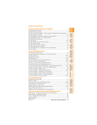
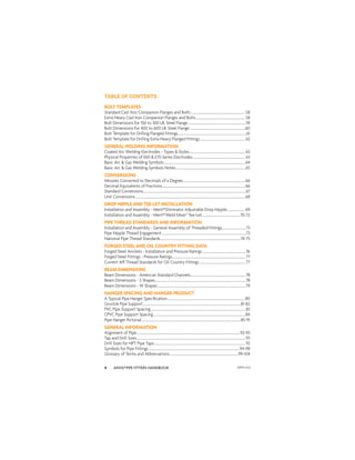
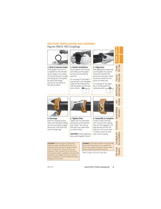
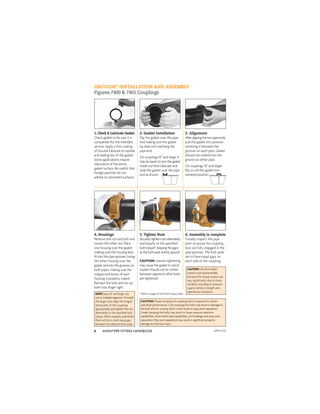
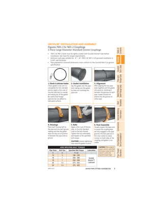
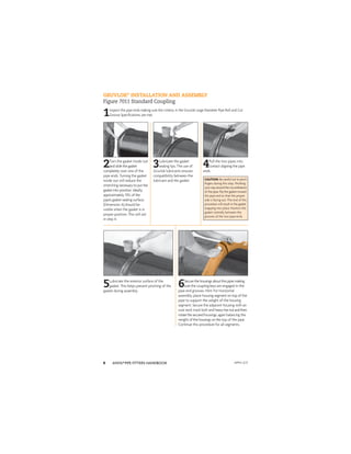
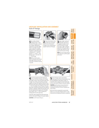
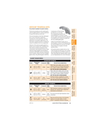
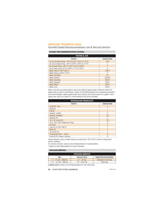
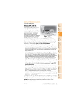
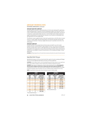
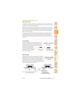
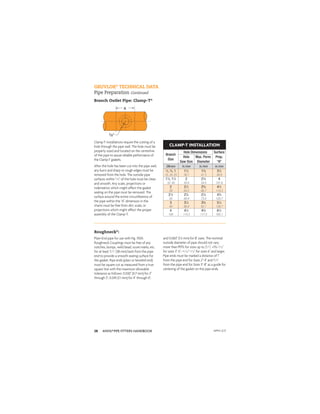
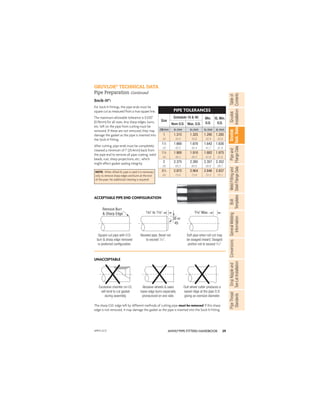
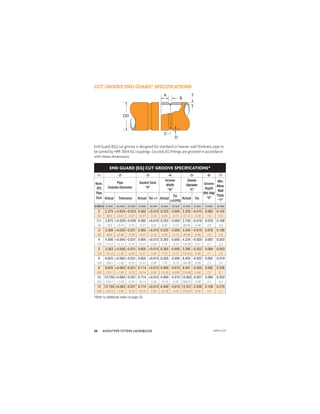
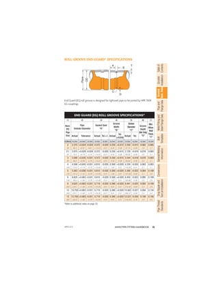
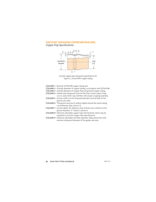
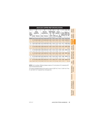
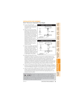
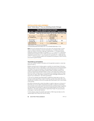
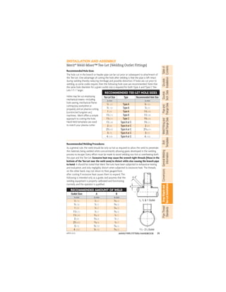
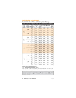
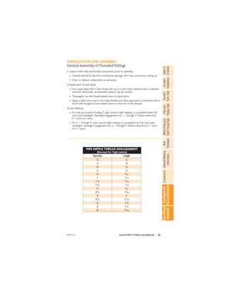
Pipe Fitters Handbook
April 2012
For the most current product/pricing
information on Anvil products, please
visit our website at www.anvilintl.com.
HISTORY
For over 150 years, Anvil has been a trusted name in piping
solutions by consistently providing quality products, service, and
support to the PVF industry. Our ability to provide cost-efficient
piping packages that are tailored to individual markets is
unmatched in the industry. From plumbing, mechanical, and fire
protection, to mining, oil and gas, our innovative responses are
designed to meet your specific demands.
PRODUCTS
Our manufacturing facilities produce an unrivaled package of
piping products, while setting a world-wide industry standard for
quality and dependability. Our ISO certified facilities use recycled
materials in the manufacturing of our product as well as being a
proud member of the USGBC.
DISTRIBUTION CHANNEL
The wholesaler has always been the key to Anvil’s business. Our
dedication to the wholesale trade is the driving force for our
services and these relationships remain a primary focus of Anvil’s
innovation. Our value-added services including a proprietary suite
of inventory management tools signifies a strong commitment to our
customers needs.
CUSTOMER SERVICE
Having major distribution centers located throughout North
America, you can count on getting the product you need - when
you need it. Customer satisfaction has always been Anvil’s #1
objective. Our experienced Sales and Customer Service Teams are
knowledgeable and eager to serve our customers, validating our
company’s motto “Building Connections that Last."
PIPE FITTINGS
3
ANVIL®PIPE FITTERS HANDBOOK
Gruvlok
Installation
Pipe
and
Flange
Data
Weld
Fitting
and
Steel
Flange
Data
Table
of
Contents
Gruvlok
Tech.
Data
Bolt
Templates
General
Welding
Information
Conversions
Drop
Nipple
and
Tee-Let
Installation
Pipe
Thread
Standards
TABLE OF CONTENTS
GRUVLOK®INSTALLATION AND ASSEMBLY
Fig. 7000 & 7001 Couplings.......................................................................................................................5
Fig. 7400 & 7401 Couplings........................................................................................................................6
Fig. 7001-2 & 7401-2 Couplings - 2 Piece Large Dia. Standard Groove Couplings........7
Fig. 7011 Standard Coupling..................................................................................................................8-9
Fig. 7400 Rigidlite®Couplings - Advanced Copper Method.................................................10
Fig. 6400 Rigid Coupling - CTS Copper System...........................................................................11
Fig. 7010 Reducing Coupling..................................................................................................................12
Fig. 7012 Flange.........................................................................................................................................13-15
Fig. 7045 & 7046 Clamp-T®Branch Outlets....................................................................................16
Fig. 7305 HDPE Coupling..........................................................................................................................17
Fig. 7307 HDPE Transition Coupling...................................................................................................18
Fig. 7004 High Pressure Coupling........................................................................................................19
Fig. 7004 High Pressure Coupling with End Guard®Gasket..................................................20
Sock-It®Fittings.............................................................................................................................................21
GRUVLOK TECHNICAL DATA
Gruvlok Gasket Grade Index.................................................................................................................23
Gruvlok Gasket Recommendation List & Vacuum Service..................................................24
Gruvlok Lubricants..............................................................................................................................25-26
Specified Bolt Torque...............................................................................................................................26
Pipe Preparation....................................................................................................................................27-29
Gruvlok Standard Roll Groove Specifications......................................................................30-31
Gruvlok Cut Groove Specifications............................................................................................32-33
Gruvlok Cut Groove End Guard Specifications...........................................................................34
Gruvlok Roll Groove End Guard Specifications..........................................................................35
Gruvlok Advanced Copper Method (IPS) - Copper Prep Specifications................36-37
Gruvlok CTS Copper System - Roll Groove Specifications.................................................38
Gruvlok Couplings - Design Factors.................................................................................................39
Gruvlok Couplings - Movement Applications......................................................................40-41
Gruvlok Couplings - Deflection from Centerline......................................................................42
Gruvlok Couplings - Range of Pipe End Separation..................................................................43
Gruvlok Fittings Flow Data - Frictional Resistance...................................................................44
Gruvlok Fittings for Grooved End Pipe....................................................................................45-46
PIPE AND FLANGE DATA
Standard Weight Pipe Data....................................................................................................................47
Barlow's Formula...........................................................................................................................................47
Commercial Pipe Sizes and Wall Thicknesses......................................................................48-49
Steel Pipe Data - Schedule 40 & 80..................................................................................................50
Copper Tube Data - Type L & K............................................................................................................51
ASTM Carbon Steel Pipe and Flange Specifications..........................................................52-53
Pipe and Water per Line Foot..............................................................................................................54
Weight per Foot of Seamless Brass and Copper Pipe.............................................................54
WELD FITTING AND STEEL FLANGE DIMENSIONAL DATA
Weld Fittings - 90˚ Elbow, 45˚ Elbow, Tee & Conc. Reducer................................................55
Weld Fittings - Welding Neck Flanges............................................................................................56
Slip-on, Threaded & Socket Flanges.................................................................................................56
Lap Joint Flanges...........................................................................................................................................57
Blind Flanges...................................................................................................................................................57
APFH-4.12
ANVIL®PIPE FITTERS HANDBOOK
4
BOLT TEMPLATES
Standard Cast Iron Companion Flanges and Bolts...................................................................58
Extra Heavy Cast Iron Companion Flanges and Bolts.............................................................58
Bolt Dimensions for 150 to 300 LB. Steel Flange.......................................................................59
Bolt Dimensions for 400 to 600 LB. Steel Flange.....................................................................60
Bolt Template for Drilling Flanged Fittings....................................................................................61
Bolt Template for Drilling Extra Heavy Flanged Fittings........................................................62
GENERAL WELDING INFORMATION
Coated Arc Welding Electrodes - Types & Styles.....................................................................63
Physical Properties of E60 & E70 Series Electrodes.................................................................63
Basic Arc & Gas Welding Symbols.....................................................................................................64
Basic Arc & Gas Welding Symbols Notes......................................................................................65
CONVERSIONS
Minutes Converted to Decimals of a Degree..............................................................................66
Decimal Equivalents of Fractions.......................................................................................................66
Standard Conversions...............................................................................................................................67
Unit Conversions.........................................................................................................................................68
DROP NIPPLE AND TEE-LET INSTALLATION
Installation and Assembly - Merit®Eliminator Adjustable Drop Nipple.......................69
Installation and Assembly - Merit®Weld Miser™Tee-Let...............................................70-72
PIPE THREAD STANDARDS AND INFORMATION
Installation and Assembly - General Assembly of Threaded Fittings..............................73
Pipe Nipple Thread Engagement.........................................................................................................73
National Pipe Thread Standards...................................................................................................74-75
FORGED STEEL AND OIL COUNTRY FITTING DATA
Forged Steel Anvilets - Installation and Pressure Ratings......................................................76
Forged Steel Fittings - Pressure Ratings...........................................................................................77
Current API Thread Standards for Oil Country Fittings.........................................................77
BEAM DIMENSIONS
Beam Dimensions - American Standard Channels....................................................................78
Beam Dimensions - S Shapes................................................................................................................78
Beam Dimensions - W Shapes.............................................................................................................79
HANGER SPACING AND HANGER PRODUCT
A Typical Pipe Hanger Specification.................................................................................................80
Gruvlok Pipe Support.........................................................................................................................81-82
PVC Pipe Support Spacing.....................................................................................................................83
CPVC Pipe Support Spacing..................................................................................................................84
Pipe Hanger Pictorial...........................................................................................................................85-91
GENERAL INFORMATION
Alignment of Pipe................................................................................................................................92-93
Tap and Drill Sizes.......................................................................................................................................93
Drill Sizes for NPT Pipe Taps.................................................................................................................93
Symbols for Pipe Fittings.................................................................................................................94-98
Glossary of Terms and Abbreviations.....................................................................................99-104
TABLE OF CONTENTS
APFH-4.12
5
ANVIL®PIPE FITTERS HANDBOOK
Gruvlok
Installation
Pipe
and
Flange
Data
Weld
Fitting
and
Steel
Flange
Data
Table
of
Contents
Gruvlok
Tech.
Data
Bolt
Templates
General
Welding
Information
Conversions
Drop
Nipple
and
Tee-Let
Installation
Pipe
Thread
Standards
GRUVLOK®
INSTALLATION AND ASSEMBLY
Figures 7000 & 7001 Couplings
1. Check & Lubricate Gasket
Check gasket to be sure it is
compatible for the intended
service. Apply a thin coating
of Gruvlok lubricant to outside
and sealing lips of the gasket.
Be careful that foreign
particles do not adhere to
lubricated surfaces.
2. Gasket Installation
Slip the gasket over the pipe
end making sure the gasket
lip does not overhang the
pipe end.
On couplings 10" and larger it
may be easier to turn the gasket
inside out then lubricate and
slide the gasket over the pipe
end as shown.
3. Alignment
Afteraligningthetwopipeends,
pull the gasket into position
centering it between the
grooves on each pipe. Gasket
should not extend into the
groove on either pipe.
On couplings 10" and larger,
flip or roll the gasket into
centered position.
4. Housings
Place the coupling housing
halves over the gasket making
sure the housing keys engage
the grooves. Insert bolts and
turn nuts finger tight.
5. Tighten Nuts
Tighten the nuts alternately
and equally to the specified
bolt torque.* The housing
bolt pads must make metal-
to-metal contact.
CAUTION: Uneven tightening
may cause the gasket to pinch.
6. Assembly is complete
Visually inspect the pipe
joint to assure the coupling
keys are fully engaged in the
pipe grooves and the bolt
pads are in firm even metal-
to-metal contact on both
sides of the coupling.
CAUTION: Proper torquing of coupling bolts is
required to obtain specified performance. Over
torquing the bolts may result in damage to the bolt
and/or casting which could result in pipe joint
separation. Under torquing the bolts may result in
lower pressure retention capabilities, lower bend load
capabilities, joint leakage and pipe joint separation.
Pipe joint separation may result in significant property
damage and serious injury.
CAUTION:Useofanimpactwrenchisnotrecommended
because the torque output can vary significantly
due to many variables including air pressure supply,
battery strength and operational variations.
* Refer to page 26 with bolt torque table
APFH-4.12
ANVIL®PIPE FITTERS HANDBOOK
6
GRUVLOK®
INSTALLATION AND ASSEMBLY
Figures 7400 & 7401 Couplings
1. Check & Lubricate Gasket
Check gasket to be sure it is
compatible for the intended
service. Apply a thin coating
of Gruvlok lubricant to outside
and sealing lips of the gasket.
Some applications require
lubrication of the entire
gasket surface. Be careful that
foreign particles do not
adhere to lubricated surfaces.
2. Gasket Installation
Slip the gasket over the pipe
end making sure the gasket
lip does not overhang the
pipe end.
On couplings 10" and larger it
may be easier to turn the gasket
inside out then lubricate and
slide the gasket over the pipe
end as shown.
3. Alignment
Afteraligningthetwopipeends,
pull the gasket into position
centering it between the
grooves on each pipe. Gasket
should not extend into the
groove on either pipe.
On couplings 10" and larger,
flip or roll the gasket into
centered position.
4. Housings
Remove one nut and bolt and
loosen the other nut. Place
one housing over the gasket,
making sure the housing keys
fit into the pipe grooves. Swing
the other housing over the
gasket and into the grooves on
both pipes, making sure the
tongue and recess of each
housing is properly mated.
Reinsert the bolt and run-up
both nuts finger tight.
5. Tighten Nuts
Securely tighten nuts alternately
and equally to the specified
bolt torque*, keeping the gaps
at the bolt pads evenly spaced.
CAUTION: Uneven tightening
may cause the gasket to pinch.
Gasket should not be visible
between segments after bolts
are tightened.
6. Assembly is complete
Visually inspect the pipe
joint to assure the coupling
keys are fully engaged in the
pipe grooves. The bolt pads
are to have equal gaps on
each side of the coupling.
CAUTION: Proper torquing of coupling bolts is required to obtain
specified performance. Over torquing the bolts may result in damage to
the bolt and/or casting which could result in pipe joint separation.
Under torquing the bolts may result in lower pressure retention
capabilities, lower bend load capabilities, joint leakage and pipe joint
separation. Pipe joint separation may result in significant property
damage and serious injury.
CAUTION:Useofanimpact
wrenchisnotrecommended
because the torque output can
vary significantly due to many
variables including air pressure
supply, battery strength and
operational variations.
* Refer to page 26 with bolt torque table.
NOTE:Sizes 16" and larger are
cast in multiple segments. To install
the larger sizes align the tongue
and pocket of the couplings
appropriately and tighten the nuts
alternately to the specified bolt
torque. When properly assembled
there will be a small equal gap
between the adjacent bolt pads.
APFH-4.12
7
ANVIL®PIPE FITTERS HANDBOOK
Gruvlok
Installation
Pipe
and
Flange
Data
Weld
Fitting
and
Steel
Flange
Data
Table
of
Contents
Gruvlok
Tech.
Data
Bolt
Templates
General
Welding
Information
Conversions
Drop
Nipple
and
Tee-Let
Installation
Pipe
Thread
Standards
GRUVLOK®
INSTALLATION AND ASSEMBLY
Figures 7001-2 & 7401-2 Couplings
2-Piece Large Diameter Standard Groove Couplings
1. Check & Lubricate Gasket
Check gasket to be sure it is
compatible for the intended
service. Apply a thin coat of
Gruvlok lubricant to outside
and sealing lips of the gasket.
Be careful that foreign
particles do not adhere to
lubricated surfaces.
2. Gasket Installation
Slip the gasket over the pipe
end, making sure the gasket
lip does not overhang the
pipe end.
3. Alignment
After aligning the two pipe
ends together, pull the gasket
into position, centering it
between the grooves on each
pipe. Gasket should not
extend into the groove on
either pipe.
4. Housings
Place each housing half on
the pipe and into each groove
making sure that the gasket
does not slip out of position
in between the pipe ends or
groove.
5. Bolts
Apply a thin coat of Xtreme
lube, or Gruvlok Standard
Lube to the bolt threads.
Tighten the nuts alternately
and equally to the specified
bolt torque.
CAUTION: Uneven tightening
may cause the gasket to pinch.
6. Final Assembly
Visually inspect the pipe joint
to assure the coupling keys
are fully engaged in the pipe
grooves, the bolt pads are in
firm even metal-to-metal
contact on both sides of the
coupling, and gasket is not
visible.
• 7001-2 & 7401-2 bolts must be lightly coated with Gruvlok Xtreme™lube before
installation. See chart for torque requirements.
• Minimum wall pipe suitable for 14" – 24": 7001-2 & 7401-2 roll grooved installation is
0.250" wall thickness.
• Pipe preparation Grooved dimensions must conform to the Gruvlok Roll/Cut groove
specification.
ANSI SPECIFIED BOLT TORQUE
Pipe Sizes Bolt Size Specified Bolt Torque Lubrication
In. In. Ft.-Lbs –
14 7
⁄8 180 - 220
Gruvlok
Xtreme™
Lubricant
16 1 250 - 300
18 1 250 - 300
20 11
⁄8 375 - 425
24 11
⁄8 375 - 425
CAUTION:When using an
impact wrench, verify that
the torque output on the
wrench is within the
required torque range.
APFH-12.11
ANVIL®PIPE FITTERS HANDBOOK
8
GRUVLOK®
INSTALLATION AND ASSEMBLY
Figure 7011 Standard Coupling
1Inspect the pipe ends making sure the criteria, in the Gruvlok Large Diameter Pipe Roll and Cut
Groove Specifications, are met.
2Turn the gasket inside out
and slide the gasket
completely over one of the
pipe ends. Turning the gasket
inside out will reduce the
stretching necessary to put the
gasket into position. Ideally,
approximately 75% of the
pipe’s gasket-sealing surface,
(Dimension A) should be
visible when the gasket is in
proper position. This will aid
in step 4.
3Lubricate the gasket
sealing lips. The use of
Gruvlok lubricants ensures
compatibility between the
lubricant and the gasket.
4Pull the two pipes into
contact aligning the pipe
ends.
CAUTION: Becarefulnottopinch
fingers during this step. Working
yourwayaroundthecircumference
of the pipe, flip the gasket toward
the pipe end so that the proper
side is facing out. The end of this
procedure will result in the gasket
snapping into place. Position the
gasket centrally between the
grooves of the two pipe ends.
5Lubricate the exterior surface of the
gasket. This helps prevent pinching of the
gasket during assembly.
6Secure the housings aboutthepipesmaking
sure the coupling keys are engaged in the
pipe end grooves. Hint: For horizontal
assembly, place housing segment on top of the
pipe to support the weight of the housing
segment. Secure the adjacent housing with an
oval neck track bolt and heavyhexnutandthen
rotatethesecuredhousings, again balancing the
weight of the housings on the top of the pipe.
Continue this procedure for all segments.
APFH-12.11
9
ANVIL®PIPE FITTERS HANDBOOK
Gruvlok
Installation
Pipe
and
Flange
Data
Weld
Fitting
and
Steel
Flange
Data
Table
of
Contents
Gruvlok
Tech.
Data
Bolt
Templates
General
Welding
Information
Conversions
Drop
Nipple
and
Tee-Let
Installation
Pipe
Thread
Standards
GRUVLOK®
INSTALLATION AND ASSEMBLY
Figure 7011 Standard Coupling Continued
CAUTION: Proper torquing of
coupling bolts is required to
obtain specified performance.
Over torquing the bolts may
result in damage to the bolt
and/or casting which could
result in pipe joint separation.
Under torquing the bolts may
result in lower pressure retention
capabilities, lower bend load
capabilities, joint leakage and
pipe joint separation. Pipe joint
separation may result in
significant property damage
and serious injury.
CAUTION:Use of an impact
wrench is not recommended
because the torque output can
vary significantly due to many
variables including air pressure
supply, battery strength and
operational variations.
7Firmly torque each bolt.
The specified minimum
torque for each nut is 600
ft.-lbs. The specified maximum
torque for each nut is 800
ft.-lbs.
8Installation of the Figure
7011 Standard Coupling is
completed.
APFH-12.11
ANVIL®PIPE FITTERS HANDBOOK
10
GRUVLOK®
INSTALLATION AND ASSEMBLY
Figure 7400 Rigidlite®
Coupling – Advanced Copper Method
1. Check & Lubricate Gasket
Check the gasket to be sure it
is compatible for the intended
service. Apply a thin coating
of Gruvlok Xtreme Lubricant
to the entire surface, both
internal and external, of the
gasket. Be careful that foreign
particles do not adhere to
lubricated surfaces.
2. Gasket Installation
Slip the gasket over the one
tube, making sure the gasket
lip does not overhang the
tube end.
3. Alignment
After aligning the two tube
ends together, pull the gasket
into position, centering it
between the grooves on each
tube. The gasket should not
extend into the groove on
either tube.
4. Housings
Remove one nut and bolt and
loosen the other nut. Place
one housing over the gasket,
making sure the housing keys
fit into the tube grooves.
Swing the other housing
over the gasket and into
the grooves on both tubes,
making sure the tongue and
recess of each housing is
properly mated. Reinsert the
bolt and run-up both nuts
finger tight.
5. Tighten Nuts
Securely tighten nuts
alternately and equally to
the specified bolt torque,*
keeping the gaps at the bolt
pads evenly spaced.
CAUTION: Uneven tightening
may cause the gasket to pinch.
Gasket should not be visible
between segments after bolts
are tightened.
6. Assembly is complete
Visually inspect the pipe
joint to assure the coupling
keys are fully engaged in the
pipe grooves. The bolt pads
are to have equal gaps on
each side of the coupling.
CAUTION: Proper torquing of coupling bolts is
required to obtain specified performance. Over
torquing the bolts may result in damage to the bolt
and/or casting which could result in pipe joint
separation. Under torquing the bolts may result in
lower pressure retention capabilities, lower bend load
capabilities, joint leakage and pipe joint separation.
Pipe joint separation may result in significant property
damage and serious injury.
CAUTION:Useofanimpactwrenchisnotrecommended
because the torque output can vary significantly
due to many variables including air pressure supply,
battery strength and operational variations.
* Refer to page 26 with bolt torque table.
APFH-12.11
11
ANVIL®PIPE FITTERS HANDBOOK
Gruvlok
Installation
Pipe
and
Flange
Data
Weld
Fitting
and
Steel
Flange
Data
Table
of
Contents
Gruvlok
Tech.
Data
Bolt
Templates
General
Welding
Information
Conversions
Drop
Nipple
and
Tee-Let
Installation
Pipe
Thread
Standards
The Fig. 6400 Coupling
from Gruvlok is specially
designed to provide a rigid
pipe connection to meet
the specific demands of
copper tubing installation.
Fast and easy swing-over
installation of the rugged
lightweight housing
produces a secure, rigid pipe
joint. Available with the
EPDM flush gap style gasket
as the standard gasket.
GRUVLOK®
INSTALLATION AND ASSEMBLY
Figure 6400 Rigid Coupling – CTS Copper System
1. Check & Lubricate Gasket
Check the gasket to be sure it
is compatible for the intended
service. Apply a thin coating
of Gruvlok®Xtreme Lubricant
to the entire surface, both
internal and external, of the
gasket. Be careful that foreign
particles do not adhere to the
lubricated surfaces.
2. Gasket Installation
Slip the gasket over one tube,
making sure the gasket lip does
not overhang the tube end.
3. Alignment
After aligning the two tube
ends together, pull the gasket
into position, centering it
between the grooves on each
tube. The gasket should not
extend into the groove on
either tube or between the
tube ends.
4. Housings
Remove one nut and bolt and
loosen the other nut. Place
one housing over the gasket,
making sure the housing keys
fit into the tube grooves.
Swing the other housing
over the gasket and into
the grooves on both tubes,
making sure the tongue and
recess of each housing is
properly mated. Re-insert the
bolt and run-up both nuts
finger tight.
CAUTION: Uneven tightening may cause the gasket
to pinch. The gasket should not be visible between
segments after the bolts are tightened. Proper
torquing of coupling bolts is required to obtain
specified performance. Over torquing the bolts may
result in damage to the bolt and/or casting which
could result in pipe joint separation. Under torquing
the bolts may result in lower pressure retention
capabilities, lower bend load capabilities, joint
leakage and pipe joint separation.
SPECIFIED BOLT TORQUE
Bolt Size Wrench Size
Specified
Bolt Torque*
In. In. Ft.-Lbs
3
⁄8
11
⁄16 30-45
1
⁄2
7
⁄8 30-45
5
⁄8 11
⁄16 60-90
* Non-lubricated bolt torques.
5. Tighten Nuts
Securely tighten nuts alternately
and equally to the specified
bolt torque, keeping the gaps
at the bolt pads evenly spaced.
Assembly is complete. Visually
inspect the pipe joint to assure
the coupling keys are fully
engaged in the pipe grooves.
The bolt pads are to have
equal gaps on each side of
the coupling.
NOTE: Copper is a soft material,
and in some cases, the bolt
pads may come close to
metal-to-metal contact.
APFH-12.11
ANVIL®PIPE FITTERS HANDBOOK
12
GRUVLOK®
INSTALLATION AND ASSEMBLY
Figure 7010 Reducing Coupling
1. Check & Lubricate Gasket
Check gasket to be sure it is
compatible for the intended
service. Apply a thin coating
of Gruvlok lubricant to
outside and sealing lips of the
gasket. Be careful that foreign
particles do not adhere to
lubricated surfaces.
2. Gasket Installation
Place the smaller opening of
the gasket over the smaller
pipe. Angle the gasket over
the pipe end and pull the
gasket lip open around the
circumference of the pipe.
The center leg of the gasket
should make flush contact
with the pipe end and will
prevent telescoping of the
smaller pipe inside the larger.
3. Alignment
Align the adjoining pipe
center lines, and insert the
larger pipe end into the
gasket. Angle the pipe end
slightly to the face of the
gasket and tilt the pipe into
the gasket to ease assembly.
4. Housings
Place the coupling
housing halves over
the gasket making
sure the housing keys
engage the grooves.
Insert bolts and turn
nuts finger tight.
5. Tighten Nuts
Tighten the nuts
alternately and equally
to the specified bolt
torque.* The housing
bolt pads must make
metal-to-metal
contact.
CAUTION: Uneven
tightening may cause
the gasket to pinch.
6. Assembly
Complete
Visually inspect the
pipe joint to assure
the coupling keys
are fully engaged in
the pipe grooves and
the bolt pads are in
firm even metal-to-
metal contact on
both sides of the
coupling.
CAUTION: Proper torquing of coupling bolts is
required to obtain specified performance. Over
torquing the bolts may result in damage to the bolt
and/or casting which could result in pipe joint
separation. Under torquing the bolts may result in
lower pressure retention capabilities, lower bend load
capabilities, joint leakage and pipe joint separation.
Pipe joint separation may result in significant property
damage and serious injury.
CAUTION:Useofanimpactwrenchisnotrecommended
because the torque output can vary significantly
due to many variables including air pressure supply,
battery strength and operational variations.
NOTE: Fig. A illustrates
the correct position
of the Fig. 7010
Reducing Coupling
gasket and housing
properly assembled
onto adjacent pipe
ends.
CAUTION: In vertical
installations the pipes
must be supported to
prevent telescoping
during installation.
Gasket
Center Rib
Proper
Position of
The Gasket
Sealing Lips
Gasket Reducing
Coupling
Housing
FIG. A
* Refer to page 26 with bolt torque table
APFH-12.11
13
ANVIL®PIPE FITTERS HANDBOOK
Gruvlok
Installation
Pipe
and
Flange
Data
Weld
Fitting
and
Steel
Flange
Data
Table
of
Contents
Gruvlok
Tech.
Data
Bolt
Templates
General
Welding
Information
Conversions
Drop
Nipple
and
Tee-Let
Installation
Pipe
Thread
Standards
1. When mating to a wafer valve (lug valve),
if the valve is rubber faced in the area
designated by the sealing surface
dimensions (A Max. to B Min.), place the
Gruvlok Flange Adapter Insert between
the valve and the Gruvlok Flange.
2. When mating to a rubber-faced metal
flange, the Gruvlok Flange Adapter Insert
is placed between the Gruvlok Flange and
the rubber-faced flange.
3. When mating to a serrated flange surface, a
standard full-faced flange gasket is installed
against the serrated flange face, and the
Gruvlok Flange Adapter Insert is placed
between the Gruvlok Flange and the
standard flange gasket.
4. When mating to valves or other component
equipment where the flange face has an
insert, use procedure described in note 3.
GRUVLOK®
INSTALLATION AND ASSEMBLY
Figure 7012 Flange (2" – 12")
Applications which require a Gruvlok Flange Adapter Insert:
Check pipe end for proper grooved dimensions and to assure that the pipe end is free of
indentations and projections that would prevent proper sealing of the Gruvlok flange gasket.
1On the side without the
hinge pin, loosen the latch
bolt nut to the end of the bolt
thread. (It is not necessary to
remove the nut from the latch
bolt.) Swing the latch bolt out
of the slot. Open the Gruvlok
Flange and place around the
grooved pipe end with the key
section fitting into the groove.
The flange gasket cavity must
face the pipe end.
2Place the latch bolt back
into the slotted hole.
Tighten the nut until there is
a 1
/16" gap between the flange
halves at location “A”. (See
Figure below)
3Check the gasket to assure
that it is properly suited
for the intended service.
Lubricate the entire exterior
surface of the gasket, including
the sealing lips, using the
proper Gruvlok lubricant.
The Gruvlok Flange gasket must be inserted so that the sealing lips face toward the pipe end
and the mating flange. The lip of the gasket, sealing on the pipe, should not extend beyond
the pipe end. The pipe should extend out beyond the end of the sealing lip by approximately
1
/8" on the 2"-6" sizes and 3
/16" on the 8"-12" sizes.
"A"
Latch Bolt
Gasket
Note: This side must
face the mating flange
APFH-12.11
ANVIL®PIPE FITTERS HANDBOOK
14
NOTE: The Gruvlok Fig. 7012 Flange
requires the use of a Flange Adapter
Insert when used against rubber
surfaces (Figure C1), serrated flange
surfaces or mating flanges with inserts
(Figure C2). The Flange Adapter Insert
will be exposed to the fluids in the
system. Ensure that the Insert is
compatible with the fluids in the
systems and with adjacent piping components.
4Stretch the Gruvlok gasket
around the pipe end and
then press the gasket into the
cavity between the pipe O.D.
and the flange. The gasket
must be properly positioned
as shown in the figure below.
GRUVLOK®
INSTALLATION AND ASSEMBLY
Figure 7012 Flange (2" – 12") Continued
CAUTION: Proper torquing of flange bolts is required to obtain specified
performance. Over torquing the bolts may result in damage to the bolt
and/or casting which could result in pipe joint separation. Under torquing
the bolts may result in lower pressure retention capabilities, lower bend
load capabilities, joint leakage and pipe joint separation. Pipe joint
separation may result in significant property damage and serious injury.
CAUTION:Use of an impact wrench is not recommended because the
torque output can vary significantly due to many variables including air
pressure supply, battery strength and operational variations.
5With the gasket in place
apply lubricant to the
exposed gasket tip, which will
seal on the mating flange.
Tighten the nuts on the latch
bolts alternately to the
specified latch bolt torque.*
The flange housings must be in
firm metal-to-metal contact.
* Refer to page 26 with bolt torque
table
6Verify that the mating
flange face is hard, flat and
smooth, free of indentations,
which would prevent proper
sealing of the Gruvlok Flange
gasket. Assure the gasket is
still in the proper position
and align Gruvlok Flange bolt
holes with the mating flange,
pump, tank, etc., bolt holes.
It is important to line up the bolt holes before bringing the two flanges
together. Sliding the flanges into place will dislodge the gasket and
cause leakage to occur. When using a flange insert, it is important that the insert is properly
aligned with the gasket prior to tightening the bolts.
7Insert a flange bolt or stud
with material properties
of SAE J429 Grade 5 or higher
through the bolt holes and
thread a nut on hand tight.
Continue this procedure until
all bolt holes have been fitted.
Tighten the nuts alternately
and evenly so the flange faces
remain parallel. All the bolts or
studs must be torqued to the
mating flange bolts specified
torque. The flange faces should
have metal-to-metal contact.
Do not use a steel Flange
Adapter Insert in copper
systems or in systems where
galvanic corrosion is possible.
FIG. C1 FIG. C2
APFH-12.11
15
ANVIL®PIPE FITTERS HANDBOOK
Gruvlok
Installation
Pipe
and
Flange
Data
Weld
Fitting
and
Steel
Flange
Data
Table
of
Contents
Gruvlok
Tech.
Data
Bolt
Templates
General
Welding
Information
Conversions
Drop
Nipple
and
Tee-Let
Installation
Pipe
Thread
Standards
4Align the Gruvlok
Flange bolt holes
with mating flange bolt
holes. Insert a flange bolt
or stud with material
properties of SAE J429
Grade 5 or higher through
the bolt holes and thread a nut on hand tight.
Insert the next bolt or stub opposite the first
and again thread the nut on hand tight. Continue
this procedure until all bolt holes have been
fitted.Insertionoftheflangeboltspriortocontact
of the flanges will help in the alignment of the
flanges. Pull the two flanges into contact using
care to assure that the gasket remains fully
seated within the gasket cavity during assembly.
NOTE: Take care to assure that the gasket lip is not
bent backwards and pinched between the two flanges.
1Place each Gruvlok Flange
segment around the
grooved pipe with the key
section fitting into the groove
and the flange gasket cavity
facing the pipe end. Loosely
assemble the segments using
the four segment-bolts-and
nuts. Alternately and equally
tighten the latch bolts and
nuts to the specified latch
bolt torque. Bring the four
flange segments into full, firm
metal-to-metal contact.
NOTE: An alternative method of
assembly is to loosely preassemble
two segments into two equal halves
of the flange leaving a small gap
(approximately 1
/8") between the
two segments of each flange- half.
Place the flange halves around the
pipe and complete the assembly
as described in Step 1, above.
GRUVLOK®
INSTALLATION AND ASSEMBLY
Figure 7012 Flange (14" – 24")
CAUTION: Proper torquing of flange bolts is required
to obtain specified performance. Over torquing the
bolts may result in damage to the bolt and/or casting
which could result in pipe joint separation. Under
torquing the bolts may result in lower pressure retention
capabilities, lower bend load capabilities, joint leakage
and pipe joint separation. Pipe joint separation may
result in significant property damage and serious injury.
CAUTION:Useofanimpactwrenchisnotrecommended
becausethetorqueoutputcanvarysignificantlydueto
manyvariablesincludingairpressuresupply,battery
strengthandoperationalvariations.
Gruvlok®
Flanges of 14" size and larger are cast in four segments to ease handling during assembly.
Figure 7012 Gruvlok Flanges should not be used with tie rods nor in a configuration with a
wafer valve between two 7012 flanges.
2Check the gasket grade to
verify that it is properly
suited for the intended service.
Lubricate the entire surface
of the gasket and the flange
cavity using the appropriate
Gruvlok Lubricant. Place the
Gruvlok Flange Gasket around
the pipe end by pressing the
gasket into the cavity between
the pipe O.D. and flange
recess. Move around the
gasket in both directions until
the gasket is fully seated in
the flange gasket cavity.
3The correct position and
relationship of the
components of the Gruvlok
Flange assembly is shown in
the Figure above. The wide
gasket lip must seal on the
pipe surface diameter and the
narrow gasket lip must face
the mating flange. Be careful
that foreign particles do not
adhere to lubricated surfaces.
NOTE: Design of the Gruvlok
Flange provides sealing only with
the special Gruvlok Flange gasket.
Only Gruvlok Flange gaskets may
be used with Fig. 7012 flanges.
CAUTION:
GASKET
MUST BE
FULLY
SEATED
AGAINST
THESE
THREE
SURFACES
14" – 24" FIG. 7012
GRUVLOK FLANGE
GASKET
PROPER POSITION OF
GASKET SEALING LIPS
PIPE SURFACE DIAMETER
5Tighten the nuts
evenly to the
specified mating face
bolt torque so that the
flange faces remain
parallel and make firm
even contact around
the entire flange.
APFH-12.11
ANVIL®PIPE FITTERS HANDBOOK
16
GRUVLOK®
INSTALLATION AND ASSEMBLY
Figures 7045 & 7046 Clamp-T®
Branch Outlets
ALWAYS USE A GRUVLOK LUBRICANT FOR PROPER COUPLING ASSEMBLY.
Thorough lubrication of the gasket is essential to assist the gasket into the proper sealing position.
BRANCH
SIZE
HOLE SAW
SIZE
(Inches) (Inches) (+1/8, -0)
1
⁄2, 3
⁄4, 1 11
⁄2
11
⁄4, 11
⁄2 2
2 21
⁄2
21
⁄2 23
⁄4
3 31
/2
4 41
/2
1. Pipe Preparation
Cut the appropriate size hole in
the pipe and remove any burrs.
Be sure to remove the slug from
inside the pipe. Clean the gasket
sealing surface within 5
/8" of
the hole and visually inspect
the sealing surface for defects
that may prevent proper sealing
of the gasket.
2. Check & Lubricate Gasket
Check the gasket to be sure it
is compatible for the intended
service. Apply a thin layer of
Gruvlok lubricant to the back
surface of the gasket. Be careful
that foreign particles do not
adhere to the lubricated
surfaces. Insert the gasket back
into the outlet housing making
sure the tabs in the gasket
line up with the tab recesses
in the housing.
3. Gasket Installation
Lubricate the exposed surface
of the gasket. Align the outlet
housing over the pipe hole
making sure that the locating
collar is in the pipe hole.
4. Alignment
Align the strap around the pipe,
insert the bolts and tighten
the nuts finger tight. Some
sizes use a U-bolt design.
5. Tighten Nuts
Alternately and evenly tighten
the nuts to the specified bolt
torque.
6. Assembly is complete
FIGS. 7045 & 7046—SPECIFIED BOLT TORQUE
Specified bolt torque is for the oval neck track bolts and U-bolts
used on the Gruvlok®Clamp-T’s. The nuts must be tightened
alternately and evenly until fully tightened.
* Non-lubricated bolt torques
ANSI SPECIFIED
BOLT TORQUE
Bolt
Size
Wrench
Size
Specified
Bolt Torque *
In. In. Ft.-Lbs.
U-Bolt 7
⁄8 30-40
1
⁄2
7
⁄8 60-80
5
⁄8 11
⁄16 100-130
3
⁄4 11
⁄4 130-180
CAUTION: Proper torquing of the bolts or U-bolts is required to obtain
the specified performance. Overtorquing the bolts or U-bolts may
result in damage to the bolt, U-bolt and/or casting which could result
in lower pressure retention capabilities, lower bend load capabilities,
pipe joint leakage and pipe joint separation.
CAUTION:Useofanimpactwrenchisnotrecommendedbecausethetorque
outputcanvarysignificantlyduetomanyvariablesincludingairpressure,battery
strengthandoperationalvariations.
APFH-12.11
17
ANVIL®PIPE FITTERS HANDBOOK
Gruvlok
Installation
Pipe
and
Flange
Data
Weld
Fitting
and
Steel
Flange
Data
Table
of
Contents
Gruvlok
Tech.
Data
Bolt
Templates
General
Welding
Information
Conversions
Drop
Nipple
and
Tee-Let
Installation
Pipe
Thread
Standards
2Check to assure
the gasket material
is acceptable for the
intended service. The
Gasket color code is
green for EPDM and
orange for Nitrile
(Buna-N).
CAUTION: Use only
Gruvlok XtremeTM
Lubricant. Gruvlok Xtreme
Lubricantcontainssilicone.
If silicone is unacceptable
fortheapplicationcontact
Gruvlok for the lubrication
recommendation. Apply
a thin coating of Gruvlok
Xtreme Lubricant to the
gasket lip and outside
surface of the gasket.
1Make certain the
pipe ends are free
of indentations,
projections or other
imperfections, which
could prevent proper
sealing of the gasket.
Mark each pipe at a
distance from the end
of the pipe according
to the pipe size:
GRUVLOK®
INSTALLATION AND ASSEMBLY
Figure 7305 HDPE Coupling
CAUTION: Proper torquing of coupling bolts is required to obtain
specified performance. Over torquing the bolts may result in damage to
the bolt and/or casting which could result in pipe joint separation.
Under torquing the bolts may result in lower pressure retention
capabilities, lower bend load capabilities, joint leakage and pipe joint
separation. Pipe joint separation may result in significant property
damage and serious injury.
CAUTION:Use of an impact wrench is not recommended because the
torque output can vary significantly due to many variables including air
pressure supply, battery strength and operational variations.
Size
Inches
Distance
to Mark
2 - 4"
(51-102mm)
1"
(25.4mm)
5 - 8"
(127-203mm)
11
⁄4"
(31.8mm)
10 & 12"
(254-305mm)
13
⁄4"
(44.5mm)
NOTE: Make certain the
HDPE pipe end is square
cut to 1
⁄8" maximum for
the 2" to 4" and 5
⁄32"
maximum for the 6" and
larger sizes.
3Slip the gasket
over one of the
pipe ends. Make sure
the gasket does not
overhang the pipe
end. Align the second
pipe and while keeping
the pipes in the butted
position slide the
gasket back over the
second pipe end. The
gasket must be
positioned centrally
between the lines on
the pipe ends.
4Place the Figure
7305 housing
casting over the
gasket, making sure
the tongue on one
casting is aligned with
the recess of the other
casting.
SPECIFIED BOLT TORQUE
Specified bolt torque is for the oval neck track bolts used on
Gruvlok®couplings. The nuts must be tightened alternately and
evenly until fully tightened.
FIG. 7305 SPECIFIED BOLT TORQUE
Coupling Bolts Minimum Maximum
In. Ft.-Lbs./N-m Ft.-Lbs./N-m
1
⁄2 X 23
⁄8
80 100
110 150
1
⁄2 X 3
80 100
110 150
5
⁄8 X 31
⁄2
100 130
135 175
3
⁄4 X 43
⁄4
130 180
175 245
5Insert the bolts and secure
the nuts alternately and
uniformly until the bolt pads
are in contact. Torque all bolts
to the required bolt torque
levels. Refer to the Specified
Bolt Torque Table. There is no
gap between the bolt pads
and the bolt torque should be
within the range given when
the coupling is properly
assembled. Alternate and even
tightening of the bolts will
significantly reduce the torque
needed to close the gap at the
pipe joint.
APFH-12.11
ANVIL®PIPE FITTERS HANDBOOK
18
GRUVLOK®
INSTALLATION AND ASSEMBLY
Figure 7307 HDPE Transition Coupling
2Check to assure
the gasket material
is acceptable for the
intended service. The
Gasket color code is
green for EPDM and
orange for Nitrile
(Buna-N).
CAUTION: Use only
Gruvlok XtremeTM
Lubricant. Gruvlok Xtreme
Lubricant contains silicone.
If silicone is unacceptable
for the application contact
Gruvlok for the lubrication
recommendation. Apply
a thin coating of Gruvlok
Xtreme Lubricant to the
gasket lips and outside
surface of the gasket.
1Make certain the
HDPE pipe end is
square cut to 1
⁄8"
maximum for the 2" to
4" and 5
⁄32" maximum
for the 6" and larger
sizes. The steel pipe
must be grooved in
accordance with
Gruvlok®Grooving
Specifications for
Steel Pipe. The pipe
ends must be free of
scratches, indentations,
projections or other
imperfections, which
could prevent proper
sealing of the gasket.
CAUTION: Proper torquing of coupling bolts is required to obtain
specified performance. Over torquing the bolts may result in damage to
the bolt and/or casting which could result in pipe joint separation.
Under torquing the bolts may result in lower pressure retention
capabilities, lower bend load capabilities, joint leakage and pipe joint
separation. Pipe joint separation may result in significant property
damage and serious injury.
CAUTION:Use of an impact wrench is not recommended because the
torque output can vary significantly due to many variables including air
pressure supply, battery strength and operational variations.
3Slip the gasket
over one of the
pipe ends. Make sure
the gasket does not
overhang the pipe end.
Align the second pipe
and while holding it
in the butted position,
slide the gasket back
over the second pipe
end. The gasket must
be positioned on the
gasket seat surface of
the grooved steel pipe.
Make sure the gasket
does not overhang
into the pipe groove.
4Place each half of
the coupling
housing over the
gasket, making sure
the housing grooved
end is directed into
the pipe groove.
SPECIFIED BOLT TORQUE
Specified bolt torque is for the oval neck track bolts used on
Gruvlok®couplings. The nuts must be tightened alternately and
evenly until fully tightened.
FIG. 7307 SPECIFIED BOLT TORQUE
Coupling Bolts Minimum Maximum
In. Ft.-Lbs./N-m Ft.-Lbs./N-m
1
⁄2 X 23
⁄8
80 100
110 150
1
⁄2 X 3
80 100
110 150
5
⁄8 X 31
⁄2
100 130
135 175
7
⁄8 X 51
⁄2
180 220
245 300
5Insert the bolts and secure
the nuts alternately and
uniformly until the bolt pads
are in contact. Torque all
bolts to the required bolt
torque levels. Refer to the
Specified Bolt Torque Table.
There is no gap between the
bolt pads and the bolt torque
should be within the range
given when the coupling is
properly assembled. Alternate
and even tightening of the
bolts will significantly reduce
the torque needed to close
the gap at the pipe joint.
APFH-12.11
19
ANVIL®PIPE FITTERS HANDBOOK
Gruvlok
Installation
Pipe
and
Flange
Data
Weld
Fitting
and
Steel
Flange
Data
Table
of
Contents
Gruvlok
Tech.
Data
Bolt
Templates
General
Welding
Information
Conversions
Drop
Nipple
and
Tee-Let
Installation
Pipe
Thread
Standards
GRUVLOK®
INSTALLATION AND ASSEMBLY
Figure 7004 High Pressure Coupling
1. Check & Lubricate Gasket
Check gasket to be sure it is
compatible for the intended
service. Apply a thin coat of
Gruvlok Lubricant to outside
and sealing lips of the gasket.
Be careful that foreign
particles do not adhere to
lubricated surfaces.
2. Gasket Installation
Slip the gasket over the pipe
end, making sure the gasket
lip does not overhang the
pipe end.
3. Alignment
After aligning the two pipe
ends together, pull the gasket
into position, centering it
between the grooves on each
pipe. Gasket should not
extend into the groove on
either pipe.
4. Housings
Place each housing halves on
the pipe making sure the
housing key fits into the
groove. Be sure that the tongue
and recess portions of the
housing mate properly. Insert
the bolts and run up the nuts
finger tight.
5. Tighten Nuts
Securely tighten nuts
alternately and equally to the
required indicator. For 2" - 4"
7004 couplings, please use
the table below for required
torque values. For 7004 5"
and larger, tighten nuts till
housings are in metal-to-
metal contact.
CAUTION: When using an impact wrench, verify
that the output of the torque wrench is within the
required torque range. It is recommended that a
torque wrench be used for accurate assembly in
order to obtain specified performance.
6. Assembly is complete
Visually inspect the pipe
joint to assure the coupling
keys are fully engaged in the
pipe grooves. For 2" - 4"
ensure the gaps on each side
are evenly space, and for 5"
and larger couplings ensure
the housings are in firm even
metal-to-metal contact on
both sides.
SPECIFIED BOLT TORQUE
Size Bolt Size Torque
In. In. Ft.-Lbs
2 5
⁄8 100 - 130
21
⁄2
5
⁄8 100 - 130
3 5
⁄8 100 - 130
4 3
⁄4 130 - 180
5 7
⁄8 *
6 7
⁄8 *
8 1 *
10 1 *
12 1 *
* Torque required to bring housing metal-to-metal contact.
APFH-12.11
ANVIL®PIPE FITTERS HANDBOOK
20
GRUVLOK®
INSTALLATION AND ASSEMBLY
Figure 7004 with EG®
Gasket
High Pressure Coupling with End Guard®
Gasket
1. Check & Lubricate Gasket
Check gasket to be sure it is
compatible for the intended
service. Apply a thin coat of
Gruvlok Lubricant to outside
and sealing lips of the gasket.
Be careful that foreign
particles do not adhere to
lubricated surfaces.
2. Gasket Installation
Slip the gasket half way on to
the pipe end, stop when the
center gasket leg comes in
contact with the pipe end.
Slide the second pipe end
half way into the gasket,
stopping then the pipe end
comes in contact with the
center gasket leg. Ensure
pipes are aligned properly.
3. Housings
Place each housing halves on
the pipe making sure the
housing key fits into the
groove. Be sure that the
tongue and recess portions of
the housing mate properly.
Insert the bolts and run up
the nuts, finger tight.
4. Tighten Nuts
Securely tighten nuts
alternately and equally to
the required indicator. For
2" - 4" couplings, please use
the table on this page for
required torque values. For
5" and larger, tighten nuts till
housings are in firm metal-to-
metal contact.
CAUTION: When using an impact wrench, verify that the output of
the torque wrench is within the required torque range. It is
recommended that a torque wrench be used for accurate assembly in
order to obtain specified performance.
5. Assembly is complete
Visually inspect the pipe
joint to assure the coupling
keys are fully engaged in the
pipe grooves. For 2" - 4"
ensure the gaps on each side
are evenly space, and for 5"
and larger couplings ensure
the housings are in firm even
metal-to-metal contact on
both sides.
SPECIFIED
BOLT TORQUE
Size Bolt Size Torque
In. In. Ft.-Lbs
2 5
⁄8 100 - 130
21
⁄2
5
⁄8 100 - 130
3 5
⁄8 100 - 130
4 3
⁄4 130 - 180
5 7
⁄8 *
6 7
⁄8 *
8 1 *
10 1 *
12 1 *
For 7400 with EG®gasket required specified
pipe end groove dimensions and fittings, see
pages 34-35 for groove dimensions.
CAUTION: Not using the correct groove dimensions
will result in pipe joint separation. Pipe joint separation
may result in significant property damage and
serious injury.
* Torque required to bring housing
metal-to-metal contact.
APFH-12.11
21
ANVIL®PIPE FITTERS HANDBOOK
Gruvlok
Installation
Pipe
and
Flange
Data
Weld
Fitting
and
Steel
Flange
Data
Table
of
Contents
Gruvlok
Tech.
Data
Bolt
Templates
General
Welding
Information
Conversions
Drop
Nipple
and
Tee-Let
Installation
Pipe
Thread
Standards
GRUVLOK®
INSTALLATION AND ASSEMBLY
Sock-It®
Fittings
4Insert the prepped and lubricated pipe
end into the Sock-It Fitting until the pipe
end makes contact with the internal pipe stop.
A slight twist while pushing fitting and pipe
together will ease the required insertion force.
The end of the Sock-It Fitting should be within
1
⁄16" from the edge of the marking on the pipe.
(See Step 1). Rotate the fitting until the desired
position is obtained. Tighten the lock bolt until
the bolt head bottoms against the threaded
boss. (NOTE: The 21
⁄2" Sock-It fitting has 2
locking bolts for each pipe end.)
Install the other prepped and lubricated pipe
end into the Sock-It fitting in the same manner.
CAUTION: Do NOT hammer fitting on.
1Pipe surface shall be
cleaned at least 1" from
the end of the pipe to remove
any coating, indentations,
projections, and sharp edges
which could affect proper
gasket sealing. As a guide for
installation, mark the pipe at
a distance of 11
⁄2" from the
end for 1", 11
⁄4", and 11
⁄2" size
fittings and 13
⁄4" for the 2" &
21
⁄2" size fittings.
NOTE: When Allied XL pipe is
used it is necessary only to remove
sharp edges and burrs at the end
of the pipe. No additional cleaning
is required.
2Check all lock bolts to be
sure they do not extend
into the I.D. of the Sock-It
Fittings as this would prevent
proper insertion of the pipe.
3Apply a light coating of
GRUVLOK Lubricant to
the gaskets located in each
end of the Sock-It Fitting.
Also apply a light coating of
lubricant to the pipe ends to
further ease insertion of the
pipe into the Sock-It Fitting.
NOTE: Use only Gruvlok Lubricants.
Other lubricants may affect gasket
performance.
5Sock-It Fittings may be removed by
loosening the lock bolts. Reinstallation may
be accomplished as described in Steps 1-4.
Install the other prepped and lubricated pipe
end into the Sock-It fitting in the same manner.
WARNING: System pressure must be relieved and
vented, and the system drained of fluid prior to
loosening the lock bolts to remove or reposition the
Sock-It Fitting.
Bolt end must be inspected to assure bolts
ability to cut into pipe. Replace bolts in cases
where bolt end sharpness has been comprised.
APFH-12.11
ANVIL®PIPE FITTERS HANDBOOK
22
NOTES
NOTES
23
ANVIL®PIPE FITTERS HANDBOOK
Gruvlok
Installation
Pipe
and
Flange
Data
Weld
Fitting
and
Steel
Flange
Data
Table
of
Contents
Gruvlok
Tech.
Data
Bolt
Templates
General
Welding
Information
Conversions
Drop
Nipple
and
Tee-Let
Installation
Pipe
Thread
Standards
GRUVLOK®
TECHNICAL DATA
Gruvlok Gasket Grade Index GRUVLOK
STANDARD GASKETS
Grade
Temperature
Range
Compound
Color
Code
General Service Applications
E -40°F to +230°F
(-40°C to 110°C)
EPDM Green
Water, dilute acids, alkalies, salts, and many
chemical services not involving hydrocarbons,
oils, or gases. Excellent oxidation resistance.
NOT FOR USE WITH HYDROCARBONS
EP -40°F to +250°F
(-40°C to 121°C)
EPDM
Green
and
Red
Water, dilute acids, alkalies, salts, and many
chemical services not involving hydrocarbons,
oils, or gases. Excellent oxidation resistance.
NOT FOR USE WITH HYDROCARBONS
T -20°F to +180°F
(-29°C to 82°C)
Nitrile
(Buna-N)
Orange
Petroleum products, vegetable oils, mineral
oils, and air contaminated with petroleum oils.
NOT FOR USE IN HOT WATER SERVICES
SPECIAL GASKETS
Grade
Temperature
Range
Compound
Color
Code
General Service Applications
O +20°F to +300°F
(-20°C to 149°C)
Fluoro
Elastomer
Blue
High temperature resistance to oxidizing acids,
petroleum oils, hydraulic fluids, halogenated,
hydrocarbons and lubricants
L -40°F to +350°F
(-40°C to 177°C)
Silicone
Red
Gasket
Dry, hot air and some high temperature chemi-
cal services.
E
Type
A
-40°F to +150°F
(-40°C to 66°C)
Pre-
Lubricated
Violet
Wet & Dry (oil free air) Pipe in Fire Protection
Systems. For dry pipe systems, Gruvlok
Xtreme™
Temperature Lubricant is required.
The lists are provided as an aid in selecting the
optimum gasket grade for a specific application
to assure the maximum service life.
The recommendations have been developed
from current information supplied by
manufacturers of the elastomers, technical
publications, and industry applications. The
information supplied should be considered as
a basis for evaluation but not as a guarantee.
Selection of the optimum gasket grade for a
specific service requires the consideration of
many factors; primarily temperature, fluid
concentration, and continuity of service. Unless
otherwise noted, all gasket recommendations
are based on 100°F (38°C) maximum temperature
service condition. Where more than one gasket
grade is shown, the preferred grade is listed first.
Combinations of fluids should
be referred to an Anvil Rep.
for an engineering evaluation and
recommendation. In unusual or severe
services, gasket materials should be subjected
to simulated service conditions to determine
the most suitable gasket grade.
Gasket recommendations apply only to
Gruvlok gaskets. Contact an Anvil Representative
for recommendations for services not listed.
These listings do not apply to Gruvlok
Butterfly Valves.
All Gruvlok products marked with UL/ULC
Listed, FM approved VdS and/or LPC symbols
are Listed/Approved with EPDM material. For
other Listed/Approved materials, please contact
an Anvil Representative for more information.
GASKET GRADE INDEX:
APFH-4.12
ANVIL®PIPE FITTERS HANDBOOK
24
GRUVLOK®
TECHNICAL DATA
Gruvlok Gasket Recommendation List & Vacuum Service
WATER & AIR
Service Gasket Grade
Air, (no oil vapors) Temp. -40°F to 230°F (-40°C to 110°C) E/EP
Air, (no oil vapors) Temp. -40°F to 350°F (-40°C to 177°C) L
Air, Oil vapor Temp. -20°F to 150°F (-29°C to 66°C) T
Air, Oil vapor Temp. 20°F to 300°F (-7°C to 149°C) O
Water, Temp to 150°F (66°C) E/EP/T
Water, Temp to 230°F (110°C) E
Water, Acid Mine E/T
Water, Chlorine (E/EP/O)
Water, Deionized E/EP/T
Water, Seawater E/EP/T
Water, Waste E/EP/T
Water, Lime E/EP/T
Where more than one gasket grade is shown the preferred gasket grade is listed first. Where the
gasket grade is shown in parentheses, Contact an Anvil Representative for an engineering evaluation
and recommendation. Specify gasket grade when ordering. Use Gruvlok lubricant on gasket. Check
gasket color code to be certain it is recommended for the service intended.
Unless otherwise noted, all gasket listings are based upon 100°F (38°C) maximum temperature
service conditions.
For services not listed, contact an Anvil Representative for recommendation.
*Contact an Anvil Representative for service evaluation.
LARGER SIZES: Contact an Anvil Representative for more information.
PETROLEUM PRODUCTS
Service Gasket Grade
Crude Oil - Sour T
Diesel Oil T
Fuel Oil T
Gasoline, Leaded T
Gasoline, Unleaded* (O)
Hydraulic Oil T
JP-3, JP-4 and JP-5 T/O
JP-6, 100°F (38°C) Maximum Temp. O
Kerosene T
Lube Oil, to 150°F (66°C) T
Motor Oil T
Tar and Tar Oil T
Transmission Fluid —Type A O
Turbo Oil #15 Diester Lubricant O
VACUUM SERVICE
Size Vacuum Level Gasket Recommendation
1" - 12" (25 - 300mm) 0" - 10" Hg Standard or Flush Gap
11
⁄2" - 12" (40 - 200mm) 10" - 29.9" Hg Flush Gap
GASKET RECOMMENDATION LISTING:
APFH-4.12
VACUUM SERVICE:
25
ANVIL®PIPE FITTERS HANDBOOK
Gruvlok
Installation
Pipe
and
Flange
Data
Weld
Fitting
and
Steel
Flange
Data
Table
of
Contents
Gruvlok
Tech.
Data
Bolt
Templates
General
Welding
Information
Conversions
Drop
Nipple
and
Tee-Let
Installation
Pipe
Thread
Standards
GRUVLOK®
TECHNICAL DATA
Gruvlok Lubricants
GRUVLOK®XTREMETM
LUBRICANT
Gruvlok®Xtreme™Lubricant has been
developed for use with Gruvlok couplings in
services where improved lubrication is
beneficial. This lubricant has an operating
temperature range from -65°F to 400°F (-53.8°C
to 204°C), well exceeding the temperature
range of Gruvlok gaskets. This lubricant is
waterproof, thereby eliminating water
wash-out and it will not dry out in the absence
of water. There are five primary applications
where the Xtreme Lubricant will provide
increased benefits: low temperature applications below -20°F(-28.0°C), high temperature
applications above 150°F (65.6°C), applications where increased pipe joint flexibility is needed,
lubrication of gaskets in copper systems, and for the lubrication of gaskets on HDPE couplings.
Since it is formulated from a non-hydro carbon base, it can be used with EPDM, Nitrile and
Fluoroelastomer gasket materials. It is not to be used with Silicone gaskets.
• In low temperature applications the gasket will shrink, thereby lowering the sealing force on
the gasket sealing lips. The temperature change will also force the gasket to slightly re-position
itself. This will cause pipe end sealing surfaces, with small cuts or damage, to become more
susceptible to leakage. Gruvlok Xtreme Lubricant will maintain its lubricating properties at lower
temperatures allowing a properly lubricated pipe end andgasket(assembly)torepositionitself
duringtemperaturecycles.
• For high temperature service and copper systems, it is required that the gasket be lubricated
not only on the outside, as with the normal installation of a Gruvlok gasket, but also on the
inside. Lubrication on the inside of the gasket is easily accomplished by turning the gasket
inside out and applying the lubricant. Gruvlok Xtreme Lubricant will maintain its lubricating
properties at higher temperatures, allowing a properly lubricated pipe end and gasket
assembly to re-position itself during temperature cycles. Lubrication of the pipe end and
gasket will help the gasket to adjust into the proper sealing position during temperature
cycles. The lubricant on the interior of the gasket will act to improve the chemical resistance of
the gasket material by providing a thin lubricant barrier between the piping system fluid and
the gasket surface. This is particularly important at higher temperatures where oxidizing agents
in the piping system become more aggressive. However, gasket chemical compatibility
must still be considered.
• The Gruvlok Xtreme Lubricant has been formulated from low viscosity, non-petroleum based
oils to ease spreading of the lubricant. In applications where pipe movement is expected,
proper lubrication of the gasket’s exterior assists the gasket into the proper sealing position as
pipe system movement occurs. This lubricating film enhances our flexible coupling gasket’s
ability to compensate for axial, transverse and rotational pipe movements.
• Gruvlok Xtreme Lubricant is the only Gruvlok lubricant that is to be used with Gruvlok couplings
and gaskets in HDPE and copper piping systems. It’s low temperature capability and lubricity
ensure a highly reliable connection.
Gruvlok®XtremeTM
Lubricant is a Teflon®fortified white, tasteless and odorless grease made from
Silicone Oil and other ingredients that are safe to ingest. It is sanctioned by the FDA under C.F.R.
21.172.878 & 21.177.1550 (Incidental Food Contact). It is NSF approved for use with potable water.
CAUTION: Silicone based lubricants are not allowed in some facilities. Do not use with CPVC Products.
®Teflon is a registered trademark of Dupont.
APFH-12.11
ANVIL®PIPE FITTERS HANDBOOK
26
GRUVLOK®
TECHNICAL DATA
Gruvlok Lubricants Continued
GRUVLOK®QUICK DRY LUBRICANT
Gruvlok®Quick Dry Lubricant is a fast drying lubricant that has been developed for applications
where the piping system is exposed. The service temperature range for this lubricant is from 0° F
to 150° F (-17.8°C to 65.6°C) and may be used with all Gruvlok gasket material grades. The lubricant
is made from a water emulsion that is non-toxic, it will not impart taste or odor, and does not
support bacterial growth. Gruvlok Quick Dry Lubricant is non-corrosive, non-flammable, and is
NSF approved for use with potable water.
This lubricant is easy to apply by brush or hand, and it quickly dries to a thin film when in contact
with air. It is water-soluble. The quick drying quality of the lubricant eliminates lubricant drips
caused by over lubrication. If necessary, reapply lubricant prior to assembly. Do not thin or mix
with solvents.
GRUVLOK®LUBRICANT
Gruvlok®Lubricant is the standard lubricant that has been provided for use with Gruvlok
products for years. Gruvlok Lubricant is water soluble, non-toxic, non-corrosive, non-flammable,
and will not impart taste or odor. It is NSF approved for use with potable water. This lubricant is
acceptable for most applications, however, the Gruvlok Xtreme Lubricant and Gruvlok Quick Dry
Lubricant are now available to improve the performance of the couplings and flanges in certain
applications.
CAUTION: HDPE pipe requires the use of Gruvlok Xtreme Lubricant and should not be used with Gruvlok Lubricant.
Specified Bolt Torque
Specified bolt torque is for the oval neck track bolts used on Gruvlok couplings and flanges.
The nuts must be tightened alternately and evenly until fully tightened.
CAUTION: Use of an Impact wrench is not recommended because the torque output can vary significantly
due to many variables including air pressure supply, battery strength and operational variations.
CAUTION: Proper torquing of coupling bolts is required to obtain specified performance. Over torquing the
bolts may result in damage to the bolt and/or casting which could result in pipe joint separation. Under
torquing the bolts may result in lower pressure retention capabilities, lower bend load capabilities, joint leakage
and pipe joint separation. Pipe joint separation may result in significant property damage and serious injury.
NOTE: Use specified bolt torque unless otherwise indicated on product installation pages.
ANSI
SPECIFIED BOLT TORQUE
Bolt
Size
Wrench
Size
Specified
Bolt Torque *
In. In. Ft.-Lbs.
3
⁄8
11
⁄16 30-45
1
⁄2
7
⁄8 80-100
5
⁄8 11
⁄16 100-130
3
⁄4 11
⁄4 130-180
7
⁄8 17
⁄16 180-220
1 15
⁄8 200-250
11
⁄8 113
⁄16 225-275
11
⁄4 2 250-300
METRIC
SPECIFIED BOLT TORQUE
Bolt
Size
Wrench
Size
Specified
Bolt Torque *
mm mm N-m
M10 16 40-60
M12 22 110-150
M16 24 135-175
M20 30 175-245
M22 34 245-300
M24 36 270-340
* Non-lubricated bolt torques
APFH-12.11
27
ANVIL®PIPE FITTERS HANDBOOK
Gruvlok
Installation
Pipe
and
Flange
Data
Weld
Fitting
and
Steel
Flange
Data
Table
of
Contents
Gruvlok
Tech.
Data
Bolt
Templates
General
Welding
Information
Conversions
Drop
Nipple
and
Tee-Let
Installation
Pipe
Thread
Standards
To create a Gruvlok pipe joint, all pipe must be prepared to receive Gruvlok coupling or other
Gruvlok pipe system components. The required pipe preparation may be grooving or cleaning
the pipe ends, or cutting a hole in the pipe wall.
For grooved-end joints, pipe may be grooved by either of two methods; cut or roll grooving.
Branch outlet connections require a properly sized and correctly located hole to be cut into the
pipe. Sock-it connections require cleaning of the pipe end. Gruvlok plain-end pipe couplings
require that the pipe be free of burrs and other sharp projections which could damage the
gasket; grooving is not required.
Gruvlok pipe grooving and hole cutting machines are available in a wide variety of designs to
meet specific or general requirements. Gruvlok roll grooving machines produce a groove to
proper dimensional tolerances, concentric with the pipe O.D., even on out-of-round pipe.
Gruvlok hole cutting tools properly center holes for correct assembly of Gruvlok branch outlet
components.
Cut-Grooving:
Cut grooving is intended for use with standard and heavier
wall pipe. Cut grooving produces a groove in the pipe wall by
removing metal from the pipe O.D. The groove removes less
than one half of the pipe wall and does not cut as deeply into
the pipe wall as do standard pipe
threads. The square cut edge of the
groove allows for the full expansion,
contraction, and deflection capabilities
of the Gruvlok coupling.
Cut Grooving
Depth of Cut Groove
vs. Thread
Volume of Metal Removed
Cut Groove vs. Threaded
Roll-Grooving:
Roll grooving does not remove metal. Instead, metal is displaced
while a groove is formed into the outer surface of the pipe wall.
The groove configuration has slightly rounded edges resulting in a
less flexible joint than a cut groove joint. This reduces available
pipe joint movement by 50% over cut grooved coupling joints. Roll
grooving is commonly used on a wide range of pipe thicknesses up
to 0.375" wall steel pipe and sizes to 24" O.D.
Roll Grooving
The I.D. “dimple" formed from roll grooving reduces the
I.D. (on an average) less than 2%.
Roll Groove
Cut Groove
Available Movement
Roll Groove vs. Cut Groove
APFH-12.11
GRUVLOK®
TECHNICAL DATA
Pipe Preparation
ANVIL®PIPE FITTERS HANDBOOK
28
Branch Outlet Pipe: Clamp-T®
Clamp-T installations require the cutting of a
hole through the pipe wall. The hole must be
properly sized and located on the centerline
of the pipe to assure reliable performance of
the Clamp-T gaskets.
After the hole has been cut into the pipe wall,
any burrs and sharp or rough edges must be
removed from the hole. The outside pipe
surfaces within 5
/8" of the hole must be clean
and smooth. Any scale, projections or
indentation which might effect the gasket
sealing on the pipe must be removed. The
surface around the entire circumference of
the pipe within the “A” dimension in the
charts must be free from dirt, scale, or
projections which might effect the proper
assembly of the Clamp-T.
A
5
⁄8"
CLAMP-T INSTALLATION
Branch
Size
Hole Dimensions Surface
Prep.
“A”
Hole
Saw Size
Max. Perm.
Diameter
DN/mm In./mm In./mm In./mm
1
⁄2, 3
⁄4, 1 11
⁄2 15
⁄8 31
⁄2
15, 20, 25 38.1 41.3 88.9
11
⁄4, 11
⁄2 2 21
⁄8 4
32, 40 50.8 54.0 101.6
2 21
⁄2 25
⁄8 41
⁄2
50 63.5 66.7 114.3
21
⁄2 23
⁄4 27
⁄8 43
⁄4
65 69.9 73.0 120.7
3 31
⁄2 35
⁄8 51
⁄2
80 88.9 92.1 139.7
4 41
⁄2 45
⁄8 61
⁄2
100 114.3 117.5 165.1
Roughneck®
:
Plain-End pipe for use with Fig. 7005
Roughneck Couplings must be free of any
notches, bumps, weld bead, score marks, etc.
for at least 11
/2" (38 mm) back from the pipe
end to provide a smooth sealing surface for
the gasket. Pipe ends (plain or beveled end)
must be square cut as measured from a true
square line with the maximum allowable
tolerance as follows: 0.030" (0.7 mm) for 2"
through 3"; 0.045 (1.1 mm) for 4" through 6";
and 0.060" (1.5 mm) for 8" sizes. The nominal
outside diameter of pipe should not vary
more than ±1% for sizes up to 21
/2", +1%-1
/32"
for sizes 3"-5"; +1
/16"-1
/32" for sizes 6" and larger.
Pipe ends must be marked a distance of 1"
from the pipe end for Sizes 2"-4" and 11
/4"
from the pipe end for Sizes 5"-8" as a guide for
centering of the gasket on the pipe ends.
APFH-12.11
GRUVLOK®
TECHNICAL DATA
Pipe Preparation Continued
29
ANVIL®PIPE FITTERS HANDBOOK
Gruvlok
Installation
Pipe
and
Flange
Data
Weld
Fitting
and
Steel
Flange
Data
Table
of
Contents
Gruvlok
Tech.
Data
Bolt
Templates
General
Welding
Information
Conversions
Drop
Nipple
and
Tee-Let
Installation
Pipe
Thread
Standards
Sock-It®
:
For Sock-It Fittings, the pipe ends must be
square cut as measured from a true square line.
The maximum allowable tolerance is 0.030"
(0.76mm) for all sizes. Any sharp edges, burrs,
etc. left on the pipe from cutting must be
removed. If these are not removed, they may
damage the gasket as the pipe is inserted into
the Sock-It Fitting.
After cutting, pipe ends must be completely
cleaned a minimum of 1" (25.4mm) back from
the pipe end to remove all pipe coating, weld
beads, rust, sharp projections, etc., which
might effect gasket sealing integrity.
PIPE TOLERANCES
Size
Schedule 10 & 40 Min.
O.D.
XL Min.
O.D.
Nom O.D. Max. O.D.
DN/mm In./mm In./mm In./mm In./mm
1 1.315 1.325 1.295 1.285
25 33.4 33.6 32.9 32.6
11
⁄4 1.660 1.670 1.642 1.630
32 42.2 42.4 41.7 41.4
11
⁄2 1.900 1.910 1.882 1.875
40 48.3 48.5 47.8 47.6
2 2.375 2.385 2.357 2.352
50 60.3 60.6 59.9 59.7
21
⁄2 2.875 2.904 2.846 2.837
65 73.0 73.8 72.3 72.1
ACCEPTABLE PIPE END CONFIGURATION
Square cut pipe with O.D.
burr & sharp edge removed
is preferred configuration.
Beveled pipe. Bevel not
to exceed 1
⁄16".
Soft pipe when roll cut may
be swaged inward. Swaged
portion not to exceed 3
⁄16"
UNACCEPTABLE
The sharp O.D. edge left by different methods of cutting pipe must be removed. If this sharp
edge is not removed, it may damage the gasket as the pipe is inserted into the Sock-It Fitting.
Excessive chamfer on I.D.
will tend to cut gasket
during assembly.
Abrasive wheels & saws
leave edge burrs especially
pronounced on one side.
Dull wheel cutter produces a
raised ridge at the pipe O.D.
giving an oversize diameter.
NOTE: When Allied XL pipe is used it is necessary
only to remove sharp edges and burrs at the end
of the pipe. No additional cleaning is required.
Remove Burr
& Sharp Edge
30 or
45
1⁄32" to 1⁄16" 3⁄16" Max.
APFH-12.11
GRUVLOK®
TECHNICAL DATA
Pipe Preparation Continued
ANVIL®PIPE FITTERS HANDBOOK
30
ROLL GROOVE SPECIFICATIONS
COLUMN 1 - Nominal IPS Pipe size. Nominal ISO Pipe size.
COLUMN 2 - IPS outside diameter. ISO outside diameter.
COLUMN 3 - Gasket seat must be free from scores, seams, chips, rust or scale
which may interfere with proper sealing of the gasket. Gasket seat
width (Dimension A) is to be measured from the pipe end to the
vertical flank in the groove wall.
COLUMN 4 - Groove width (Dimension B) is to be measured between vertical
flank of the groove size walls.
COLUMN 5 - The groove must be of uniform depth around the entire pipe
circumference. (See column 6).
COLUMN 6 - Groove depth: for reference only. Groove must conform to the
groove diameter “C” listed in column 5.
COLUMN 7 - Minimum allowable wall thickness which may be roll grooved.
COLUMN 8 - Maximum allowable pipe end flare diameter. Measured at the
most extreme pipe end diameter of the gasket seat area.
Out of roundness: Difference between maximum O.D. and minimum O.D. mea-
sured at 90° must not exceed total O.D. tolerance listed (reference column 2).
For IPS pipe, the maximum allowable tolerance from square cut ends is 0.03" for
1" thru 31
⁄2"; 0.045" for 4" thru 6"; and 0.060" for sizes 8" and above measured from
a true square line.
For ISO size pipe, the maximum allowable tolerance from square cut ends is
0.75mm for sizes 25mm-80mm; 1.15mm for sizes 100mm-150mm; and 1.50mm for
sizes 200mm and above, measured from a true square line.
Beveled-End Pipe in conformance with ANSI B16.25 (371
⁄2°) is acceptable, how-
ever square cut is preferred. Seams must be ground flush with the pipe O.D. and
ID prior to roll grooving. Failure to do so may result in damage to the roll groov-
ing machine and unacceptable roll grooves may be produced.
Weld Seams must be ground flush with the pipe O.D. and ID prior to roll groov-
ing. Failure to do so may result in damage to the roll grooving machine and unac-
ceptable roll grooves may be produced.
▼ “A” tolerance +0.030" / -0.060" (+0.77 / -1.54 mm)
T
B
D
C
OD
Flare
A
NOTE: VdS - Roll Grooving Approval Specifications, see the Technical Data/Install Instructions section on
Anvil’s web site - www.anvilintl.com
APFH-12.11
31
ANVIL®PIPE FITTERS HANDBOOK
Gruvlok
Installation
Pipe
and
Flange
Data
Weld
Fitting
and
Steel
Flange
Data
Table
of
Contents
Gruvlok
Tech.
Data
Bolt
Templates
General
Welding
Information
Conversions
Drop
Nipple
and
Tee-Let
Installation
Pipe
Thread
Standards
GRUVLOK STANDARD ROLL GROOVE SPECIFICATION
FOR STEEL & OTHER IPS OR ISO SIZE PIPE
-1- -2- -3- -4- -5- -6- -7- -8-
Nom.
Pipe
Size
O.D. “A”
±0.030/
±0.76
“B”
±0.030/
±0.76
“C”
Actual
“C” Tol.
+0.000
“D”
(Ref.Only)
“T”Min.
Allow.
WallThick
Max.
Flare
Dia.
Actual Tolerance
In./DN(mm) In./mm +In./mm -In./mm In./mm In./mm In./mm -In./mm In./mm In./mm In./mm
1 1.315 +0.028 -0.015 0.625 0.281 1.190 -0.015 0.063 0.065 1.430
25 33.4 +0.71 -0.38 15.88 7.14 30.23 -0.38 1.60 1.7 36.3
11
⁄4 1.660 +0.029 -0.016 0.625 0.281 1.535 -0.015 0.063 0.065 1.770
32 42.2 +0.74 -0.41 15.88 7.14 38.99 -0.38 1.60 1.7 45.0
11
⁄2 1.900 +0.019 -0.019 0.625 0.281 1.775 -0.015 0.063 0.065 2.010
40 48.3 +0.48 -0.48 15.88 7.14 45.09 -0.38 1.60 1.7 51.1
2 2.375 +0.024 -0.024 0.625 0.344 2.250 -0.015 0.063 0.065 2.480
50 60.3 +0.61 -0.61 15.88 8.74 57.15 -0.38 1.60 1.7 63.0
21
⁄2 2.875 +0.029 -0.029 0.625 0.344 2.720 -0.018 0.078 0.083 2.980
65 73.0 +0.74 -0.74 15.88 8.74 69.09 -0.46 1.98 2.1 75.7
3 O.D. 2.996 +0.030 -0.030 0.625 0.344 2.845 -0.018 0.076 0.083 3.100
76.1 76.1 +0.76 -0.76 15.88 8.74 72.26 -0.46 1.93 2.1 78.7
3 3.500 +0.035 -0.031 0.625 0.344 3.344 -0.018 0.078 0.083 3.600
80 88.9 +0.89 -0.79 15.88 8.74 84.94 -0.46 1.98 2.1 91.4
31
⁄2 4.000 +0.040 -0.031 0.625 0.344 3.834 -0.020 0.083 0.083 4.100
90 101.6 +1.02 -0.79 15.88 8.74 97.38 -0.51 2.11 2.1 104.1
41
⁄4 O.D. 4.250 +0.042 -0.031 0.625 0.344 4.084 -0.020 0.083 0.083 4.350
108.0 108.0 +1.07 -0.79 15.88 8.74 103.73 -0.51 2.11 2.1 110.5
4 4.500 +0.045 -0.031 0.625 0.344 4.334 -0.020 0.083 0.083 4.600
100 114.3 +1.14 -0.79 15.88 8.74 110.08 -0.51 2.11 2.1 116.8
51
⁄4 O.D. 5.236 +0.052 -0.031 0.625 0.344 5.084 -0.020 0.076 0.109 5.350
133.0 133.0 +1.32 -0.79 15.88 8.74 129.13 -0.51 1.93 2.8 135.9
51
⁄2 O.D. 5.500 +0.055 -0.031 0.625 0.344 5.334 -0.020 0.083 0.109 5.600
139.7 139.7 +1.40 -0.79 15.88 8.74 135.48 -0.51 2.11 2.8 142.2
5 5.563 +0.056 -0.031 0.625 0.344 5.395 -0.022 0.084 0.109 5.660
125 141.3 +1.42 -0.79 15.88 8.74 137.03 -0.56 2.13 2.8 143.8
61
⁄4 O.D. 6.259 +0.063 -0.031 0.625 0.344 6.084 -0.022 0.088 0.109 6.350
159.0 159.0 +1.60 -0.79 15.88 8.74 154.53 -0.56 2.24 2.8 161.3
61
⁄2 O.D. 6.500 +0.063 -0.031 0.625 0.344 6.334 -0.022 0.085 0.109 6.600
165.1 165.1 +1.60 -0.79 15.88 8.74 160.88 -0.56 2.16 2.8 167.6
6 6.625 +0.063 -0.031 0.625 0.344 6.455 -0.022 0.085 0.109 6.730
150 168.3 +1.60 -0.79 15.88 8.74 163.96 -0.56 2.16 2.8 170.9
8 8.625 +0.063 -0.031 0.750 0.469 8.441 -0.025 0.092 0.109 8.800
200 219.1 +1.60 -0.79 19.05 11.91 214.40 -0.64 2.34 2.8 223.5
10 10.750 +0.063 -0.031 0.750 0.469 10.562 -0.027 0.094 0.134 10.920
250 273.1 +1.60 -0.79 19.05 11.91 268.27 -0.69 2.39 3.4 277.4
12 12.750 +0.063 -0.031 0.750 0.469 12.531 -0.030 0.109 0.156 12.920
300 323.9 +1.60 -0.79 19.05 11.91 318.29 -0.76 2.77 4.0 328.2
14O.D. 14.000 +0.063 -0.031 0.938 0.469 13.781 -0.030 0.109 0.156 14.100
355.6 355.6 +1.60 -0.79 23.83 11.91 350.04 -0.76 2.77 4.0 358.1
16O.D. 16.000 +0.063 -0.031 0.938 0.469 15.781 -0.030 0.109 0.165 16.100
406.4 406.4 +1.60 -0.79 23.83 11.91 400.84 -0.76 2.77 4.2 408.9
18O.D. 18.000 +0.063 -0.031 1.000 0.469 17.781 -0.030 0.109 0.165 18.160
457.2 457.2 +1.60 -0.79 25.40 11.91 451.64 -0.76 2.77 4.2 461.3
20O.D. 20.000 +0.063 -0.031 1.000 0.469 19.781 -0.030 0.109 0.188 20.160
508.0 508.0 +1.60 -0.79 25.40 11.91 502.44 -0.76 2.77 4.8 512.1
24O.D. 24.000 +0.063 -0.031 1.000 0.500 23.656 -0.030 0.172 0.218 24.200
609.6 609.6 +1.60 -0.79 25.40 12.70 600.86 -0.76 4.37 5.5 614.7
30O.D. 30.000 +0.093 -0.031 1.750▼ 0.625 29.500 -0.063 0.250 0.250 30.200
762.0 762.0 2.36 0.79 44.45 15.88 749.30 1.60 6.35 6.35 761.1
APFH-12.11
ANVIL®PIPE FITTERS HANDBOOK
32
T
B
D
C
OD
A
CUT GROOVE SPECIFICATIONS
COLUMN 1 - Nominal IPS Pipe size. Nominal ISO Pipe size.
COLUMN 2 - IPS outside diameter. ISO outside diameter.
COLUMN 3 & 4 - Gasket seat must be free from scores, seams, chips, rust or
scale which may interfere with proper coupling assembly.
COLUMN 5 - The groove must be of uniform depth around the entire pipe
circumference. (See column 6).
COLUMN 6 - Groove depth: for reference only. Groove must conform to the
groove diameter “C” listed in column 5.
COLUMN 7 - Minimum allowable wall thickness which may be cut grooved.
Out of roundness: Difference between maximum O.D. and minimum O.D. mea-
sured at 90° must not exceed total O.D. tolerance listed (reference column 2).
For IPS pipe, the maximum allowable tolerance from square cut ends is 0.03" for
1" thru 31
⁄2"; 0.045" for 4" thru 6"; and 0.060" for sizes 8" and above measured from
a true square line.
For ISO size pipe, the maximum allowable tolerance from square cut ends is
0.75mm for sizes 25mm-80mm; 1.15mm for sizes 100mm-150mm; and 1.50mm for
sizes 200mm and above, measured from a true square line.
Beveled-End Pipe in conformance with ANSI B16.25 (371
⁄2°) is acceptable, how-
ever square cut is preferred. Not to be used with End Guard gaskets.
▼ “A” tolerance +0.030" / -0.060" (+0.77 / -1.54 mm)
APFH-12.11
33
ANVIL®PIPE FITTERS HANDBOOK
Gruvlok
Installation
Pipe
and
Flange
Data
Weld
Fitting
and
Steel
Flange
Data
Table
of
Contents
Gruvlok
Tech.
Data
Bolt
Templates
General
Welding
Information
Conversions
Drop
Nipple
and
Tee-Let
Installation
Pipe
Thread
Standards
GRUVLOK STANDARD CUT GROOVE SPECIFICATION
FOR STEEL & OTHER IPS OR ISO SIZE PIPE
-1- -2- -3- -4- -5- -6- -7-
Nom.
IPS Pipe
Size
O.D.
Gasket
Seat “A”
±0.030
±0.76
Groove
Width “B”
±0.030
±0.76
Groove Diameter
“C”
Actual
Groove
Depth “D”
(Ref. Only)
Min.
Allow.
Wall
Thick.“T”
Actual Tolerance Actual
Tol.
+0.000
In./DN(mm) In./mm +In./mm -In./mm In./mm In./mm In./mm -In./mm In./mm In./mm
1 1.315 +0.028 -0.015 0.625 0.312 1.190 -0.015 0.062 0.133
25 33.4 +0.71 -0.38 15.88 7.92 30.23 -0.38 1.6 3.4
11
⁄4 1.660 +0.029 -0.016 0.625 0.312 1.535 -0.015 0.062 0.140
32 42.2 +0.74 -0.41 15.88 7.92 38.99 -0.38 1.6 3.6
11
⁄2 1.900 +0.019 -0.019 0.625 0.312 1.775 -0.015 0.062 0.145
40 48.3 +0.48 -0.48 15.88 7.92 45.09 -0.38 1.6 3.7
2 2.375 +0.024 -0.024 0.625 0.312 2.250 -0.015 0.062 0.154
50 60.3 +0.61 -0.61 15.88 7.92 57.15 -0.38 1.6 3.9
21
⁄2 2.875 +0.029 -0.029 0.625 0.312 2.720 -0.018 0.078 0.187
65 73.0 +0.74 -0.74 15.88 7.92 69.09 -0.46 2.0 4.8
3 O.D. 2.996 +0.030 -0.030 0.625 0.312 2.845 -0.018 0.076 0.188
76.1 76.1 +0.76 -0.76 15.88 7.92 72.26 -0.46 1.9 4.8
3 3.500 +0.035 -0.031 0.625 0.312 3.344 -0.018 0.078 0.188
80 88.9 +0.89 -0.79 15.88 7.92 84.94 -0.46 2.0 4.8
31
⁄2 4.000 +0.040 -0.031 0.625 0.312 3.834 -0.020 0.083 0.188
90 101.6 +1.02 -0.79 15.88 7.92 97.38 -0.51 2.1 4.8
41
⁄4 O.D. 4.250 +0.042 -0.031 0.625 0.375 4.084 -0.020 0.083 0.203
108.0 108.0 +1.07 -0.79 15.88 9.53 103.73 -0.51 2.1 5.2
4 4.500 +0.045 -0.031 0.625 0.375 4.334 -0.020 0.083 0.203
100 114.3 +1.14 -0.79 15.88 9.53 110.08 -0.51 2.1 5.2
51
⁄4 O.D. 5.236 +0.052 -0.031 0.625 0.375 5.084 -0.020 0.076 0.203
133.0 133.0 +1.32 -0.79 15.88 9.53 129.13 -0.51 1.9 5.2
51
⁄2 O.D. 5.500 +0.055 -0.031 0.625 0.375 5.334 -0.020 0.083 0.203
139.7 139.7 +1.40 -0.79 15.88 9.53 135.48 -0.51 2.1 5.2
5 5.563 +0.056 -0.031 0.625 0.375 5.395 -0.022 0.084 0.203
125 141.3 +1.42 -0.79 15.88 9.53 137.03 -0.56 2.1 5.2
61
⁄4 O.D. 6.259 +0.063 -0.031 0.625 0.375 6.084 -0.022 0.088 0.249
159.0 159.0 +1.60 -0.79 15.88 9.53 154.53 -0.56 2.2 6.3
61
⁄2 O.D. 6.500 +0.063 -0.031 0.625 0.375 6.334 -0.022 0.085 0.219
165.1 165.1 +1.60 -0.79 15.88 9.53 160.88 -0.56 2.2 5.6
6 6.625 +0.063 -0.031 0.625 0.375 6.455 -0.022 0.085 0.219
150 168.3 +1.60 -0.79 15.88 9.53 163.96 -0.56 2.2 5.6
8 8.625 +0.063 -0.031 0.750 0.437 8.441 -0.025 0.092 0.238
200 219.1 +1.60 -0.79 19.05 11.10 214.40 -0.64 2.3 6.1
10 10.750 +0.063 -0.031 0.750 0.500 10.562 -0.027 0.094 0.250
250 273.1 +1.60 -0.79 19.05 12.70 268.27 -0.69 2.4 6.4
12 12.750 +0.063 -0.031 0.750 0.500 12.531 -0.030 0.109 0.279
300 323.9 +1.60 -0.79 19.05 12.70 318.29 -0.76 2.8 7.1
14 O.D. 14.000 +0.063 -0.031 0.938 0.500 13.781 -0.030 0.109 0.281
355.6 355.6 +1.60 -0.79 23.83 12.70 350.04 -0.76 2.8 7.1
16 O.D. 16.000 +0.063 -0.031 0.938 0.500 15.781 -0.030 0.109 0.312
406.4 406.4 +1.60 -0.79 23.83 12.70 400.84 -0.76 2.8 7.9
18 O.D. 18.000 +0.063 -0.031 1.000 0.500 17.781 -0.030 0.109 0.312
457.2 457.2 +1.60 -0.79 25.40 12.70 451.64 -0.76 2.8 7.9
20 O.D. 20.000 +0.063 -0.031 1.000 0.500 19.781 -0.030 0.109 0.312
508.0 508.0 +1.60 -0.79 25.40 12.70 502.44 -0.76 2.8 7.9
24 O.D. 24.000 +0.063 -0.031 1.000 0.563 23.656 -0.030 0.172 0.375
609.6 609.6 +1.60 -0.79 25.40 14.30 600.86 -0.76 4.4 9.5
28 I.D. 28.875 +0.063 -0.031 1.000 0.563 28.531 -0.030 0.172 0.437
733.4 733.4 +1.60 -0.79 25.40 14.30 724.69 -0.76 4.4 11.1
30 I.D. 31.000 +0.063 -0.031 1.250 0.625 30.594 -0.030 0.203 0.500
787.4 787.4 +1.60 -0.79 31.75 15.88 777.09 -0.76 5.2 12.7
30 O.D. 30.000 0.093 0.031 1.750▼ 0.625 29.500 0.063 0.250 0.625
762.0 762.0 2.36 0.79 44.45 15.88 749.30 1.60 6.35 15.88
APFH-12.11
ANVIL®PIPE FITTERS HANDBOOK
34
CUT GROOVE END GUARD®
SPECIFICATIONS
End Guard (EG) cut groove is designed for standard or heavier wall thickness pipe to
be joined by HPR 7004 EG couplings. Gruvlok EG fittings are grooved in accordance
with these dimensions.
END GUARD (EG) CUT GROOVE SPECIFICATIONS*
-1- -2- -3- -4- -5- -6- -7-
Nom.
IPS
Pipe
Size
Pipe
Outside Diameter
Gasket Seat
“A”
Groove
Width
“B”
Groove
Diameter
“C”
Groove
Depth
(Ref.Only)
“D”
Min.
Allow.
Wall
Thick.
“T”
Actual Tolerance Actual Tol.+/- Actual
Tol.
(+0.010)
Actual Tol.
In./DN(mm) In./mm +In./mm -In./mm In./mm In./mm In./mm -In./mm In./mm In./mm In./mm In./mm
2 2.375 +0.024 -0.024 0.562 +0.010 0.255 -0.005 2.250 -0.015 0.062 0.154
50 60.3 +0.61 -0.61 14.27 0.25 6.48 -0.13 57.15 -0.38 1.6 4.0
21
⁄2 2.875 +0.029 -0.029 0.562 +0.010 0.255 -0.005 2.720 -0.018 0.078 0.188
65 73.0 +0.74 -0.74 14.27 0.25 6.48 -0.13 69.09 -0.46 2.0 4.8
3 3.500 +0.035 -0.031 0.562 +0.010 0.255 -0.005 3.344 -0.018 0.078 0.188
80 88.9 +0.89 -0.79 14.27 0.25 6.48 -0.13 84.94 -0.46 2.0 4.8
4 4.500 +0.045 -0.031 0.605 +0.015 0.305 -0.005 4.334 -0.020 0.083 0.203
100 114.3 +1.14 -0.79 15.37 0.38 7.75 -0.13 110.08 -0.51 2.1 5.2
5 5.563 +0.056 -0.031 0.605 +0.015 0.305 -0.005 5.395 -0.022 0.084 0.203
125 141.3 +1.42 -0.79 15.37 0.38 7.75 -0.13 137.03 -0.56 2.1 5.2
6 6.625 +0.063 -0.031 0.605 +0.015 0.305 -0.005 6.455 -0.022 0.085 0.219
150 168.3 +1.60 -0.79 15.37 0.38 7.75 -0.13 163.96 -0.56 2.2 5.6
8 8.625 +0.063 -0.031 0.714 +0.015 0.400 -0.010 8.441 -0.025 0.092 0.238
200 219.1 +1.60 -0.79 18.14 0.38 10.16 -0.254 214.40 -0.64 2.3 6.1
10 10.750 +0.063 -0.031 0.714 +0.015 0.400 -0.010 10.562 -0.027 0.094 0.250
250 273.1 +1.60 -0.79 18.14 0.38 10.16 -0.25 268.27 -0.69 2.4 6.4
12 12.750 +0.063 -0.031 0.714 +0.015 0.400 -0.010 12.531 -0.030 0.109 0.279
300 323.9 +1.60 -0.79 18.14 0.38 10.16 -0.25 318.29 -0.76 2.8 7.1
T
B
D
C
OD
A
*Refer to additional notes on page 32.
APFH-12.11
35
ANVIL®PIPE FITTERS HANDBOOK
Gruvlok
Installation
Pipe
and
Flange
Data
Weld
Fitting
and
Steel
Flange
Data
Table
of
Contents
Gruvlok
Tech.
Data
Bolt
Templates
General
Welding
Information
Conversions
Drop
Nipple
and
Tee-Let
Installation
Pipe
Thread
Standards
ROLL GROOVE END GUARD®
SPECIFICATIONS
End Guard (EG) roll groove is designed for lightwall pipe to be joined by HPR 7004
EG couplings.
END GUARD (EG) ROLL GROOVE SPECIFICATIONS*
-1- -2- -3- -4- -5- -6- -7-
Nom.
IPS
Pipe
Size
Pipe
Outside Diameter
Gasket Seat
“A”
Groove
Width
“B”
Groove
Diameter
“C”
Groove
Depth
(Ref.Only)
“D”
Min.
Allow.
Wall
Thick.
“T”
Actual Tolerance Actual Tol.+/- Actual
Tol.
(+0.010)
Actual Tol.
In./DN(mm) In./mm +In./mm -In./mm In./mm In./mm In./mm -In./mm In./mm In./mm In./mm In./mm
2 2.375 +0.024 -0.024 0.572 -0.020 0.250 +0.015 2.250 -0.015 0.062 0.065
50 60.3 +0.61 -0.61 +14.53 -0.51 6.35 0.38 57.15 -0.38 1.6 1.7
21
⁄2 2.875 +0.029 -0.029 0.572 -0.020 0.250 +0.015 2.720 -0.018 0.078 0.083
65 73.0 +0.74 -0.74 +14.53 -0.51 6.35 0.38 69.09 -0.46 2.0 2.1
3 3.500 +0.035 -0.031 0.572 -0.020 0.250 +0.015 3.344 -0.018 0.078 0.083
80 88.9 +0.89 -0.79 +14.53 -0.51 6.35 0.38 84.94 -0.46 2.0 2.1
4 4.500 +0.045 -0.031 0.610 -0.020 0.300 +0.020 4.334 -0.020 0.083 0.083
100 114.3 +1.14 -0.79 +15.49 -0.51 7.62 0.51 110.08 -0.51 2.1 2.1
5 5.563 +0.056 -0.031 0.610 -0.020 0.300 +0.020 5.395 -0.022 0.084 0.109
125 141.3 +1.42 -0.79 +15.49 -0.51 7.62 0.51 137.03 -0.56 2.1 2.8
6 6.625 +0.063 -0.031 0.610 -0.020 0.300 +0.020 6.455 -0.022 0.085 0.109
150 168.3 +1.60 -0.79 +15.49 -0.51 7.62 0.51 163.96 -0.56 2.2 2.8
8 8.625 +0.063 -0.031 0.719 -0.020 0.390 +0.020 8.441 -0.025 0.092 0.109
200 219.1 +1.60 -0.79 +18.26 -0.51 9.91 0.51 214.40 -0.64 2.3 2.8
10 10.750 +0.063 -0.031 0.719 -0.020 0.390 +0.020 10.562 -0.027 0.094 0.134
250 273.1 +1.60 -0.79 +18.26 -0.51 9.91 0.51 268.27 -0.69 2.4 3.4
12 12.750 +0.063 -0.031 0.719 -0.020 0.390 +0.020 12.531 -0.030 0.109 0.156
300 323.9 +1.60 -0.79 +18.26 -0.51 9.91 0.51 318.29 -0.76 2.8 4.0
*Refer to additional notes on page 32.
T
B
D
C
OD
Flare
A
APFH-12.11
ANVIL®PIPE FITTERS HANDBOOK
36
GRUVLOK®
ADVANCED COPPER METHOD (IPS)
Copper Prep Specifications
Gruvlok copper prep roll groove specifications for
Types K, L, M and DWV copper tubing
B
A T
C
D
Connection
Diameter
Tube
O.D.
COLUMN 1 - Nominal ASTM B 88 copper tubing size.
COLUMN 2 - Outside diameter of copper tubing in accordance with ASTM B 88.
COLUMN 3 - Outside diameter of Copper Prep roll grooved copper tubing.
COLUMN 4 - Gasket seat and groove must be free from scores, seams, chips,
rust or scale which may interfere with proper coupling assembly.
COLUMN 5 - Groove width is to be measured between vertical flank of the
groove size walls.
COLUMN 6 - The groove must be of uniform depth around the entire tubing
circumference. (See column 7).
COLUMN 7 - Groove depth: for reference only. Groove must conform to the
groove diameter “C” listed in column 6.
COLUMN 8 - Minimum allowable copper tube wall thickness which may be
prepared to Gruvlok Copper-Prep specifications.
COLUMN 9 - Maximum allowable end flare diameter. Measured at the most
extreme tubing end diameter of the gasket seat area.
APFH-12.11
37
ANVIL®PIPE FITTERS HANDBOOK
Gruvlok
Installation
Pipe
and
Flange
Data
Weld
Fitting
and
Steel
Flange
Data
Table
of
Contents
Gruvlok
Tech.
Data
Bolt
Templates
General
Welding
Information
Conversions
Drop
Nipple
and
Tee-Let
Installation
Pipe
Thread
Standards
NOTES: Out of roundness: Difference between maximum O.D. and minimum O.D. measured at 90°
must not exceed tolerance listed.
The maximum allowable tolerance from square cut ends is 0.030" for 2" thru 3"; 0.045" for 4" thru
6"; and 0.060" for 8" measured from a true square line.
GRUVLOK COPPER PREP SPECIFICATIONS
-1- -2- -3- -4- -5- -6- -7- -8- -9-
Nom.
Tubing
Size
Tubing
Outside Dia.
Tube End
Connection Dia.
Gasket
Seat
A
± .030
± .77
Groove
Width
B
± .030
± .77
Groove
Diameter “C” Groove
Depth D
(Ref. Only)
Allow
Wall
Thick
T
Max.
Flare
Dia.
Actual Tolerance Actual Tolerance Actual
Tol.
+0.000
In./DN(mm) In./mm +In./mm –In./mm In./mm +In./mm –In./mm In./mm In./mm In./mm –In./mm In./mm In./mm In./mm
2 2.125 0.002 0.002 2.375 0.045 0.024 0.625 0.344 2.250 -0.015 0.063 0.059 2.447
50 54.0 0.05 0.05 60.33 1.14 0.61 15.88 8.74 57.15 -0.381 1.60 1.50 62.15
21
⁄2 2.625 0.002 0.002 2.875 0.029 0.029 0.625 0.344 2.720 -0.018 0.077 0.065 2.962
65 66.7 0.05 0.05 73.03 0.74 0.74 15.88 8.74 69.09 -0.46 1.96 1.65 75.23
3 3.125 0.002 0.002 3.500 0.035 0.031 0.625 0.344 3.344 -0.018 0.078 DWV 3.566
80 79.4 0.05 0.05 88.90 0.89 0.79 15.88 8.74 84.94 -0.46 1.98 90.58
4 4.125 0.002 0.002 4.500 0.045 0.031 0.625 0.344 4.334 -0.020 0.083 DWV 4.576
100 104.8 0.05 0.05 114.30 1.14 0.79 15.88 8.74 110.08 -0.51 2.11 116.23
5 5.125 0.002 0.002 5.562 0.056 0.031 0.625 0.344 5.395 -0.022 0.084 DWV 5.650
125 130.2 0.05 0.05 141.27 1.42 0.79 15.88 8.74 137.03 -0.56 2.13 143.51
6 6.125 0.002 0.002 6.625 0.063 0.031 0.625 0.344 6.455 -0.022 0.085 DWV 6.719
150 155.6 0.05 0.05 168.28 1.60 0.79 15.88 8.74 163.96 -0.56 2.16 170.66
8 8.125 0.002 0.004 8.625 0.063 0.031 0.750 0.469 8.441 -0.025 0.092 DWV 8.719
200 206.4 0.05 0.10 219.08 1.60 0.79 19.05 11.91 214.40 -0.64 2.34 221.46
APFH-12.11
ANVIL®PIPE FITTERS HANDBOOK
38
GRUVLOK CTS COPPER SYSTEM – ROLL GROOVE SPECIFICATIONS
-1- -2- -3- -4- -5- -6- -7- -8-
Nom.
Size
Tubing
Outside Diameter
Gasket Seat
“A”
+/– 0.03 in.
+/– 0.76mm
Groove Width
“B”
+0.03/–0.00 in.
+0.76/–0.00mm
Groove Diameter
“C”
Nom.
Groove
Depth
“D”
Min.
Wall
“T”
Max.
Flare
Diam.
Actual Tolerance Actual
Tolerance
+0.000
In. In./mm +In./mm –In./mm In./mm In./mm In./mm –In./mm In./mm In./mm In./mm
2
2.125 0.002 0.002 0.610 0.300 2.029 -0.020 0.048 0.058 2.220
54.0 0.05 0.05 15.5 7.6 51.54 -0.51 1.2 1.6 56.4
21
⁄2
2.625 0.002 0.002 0.610 0.300 2.525 -0.020 0.050 0.065 2.720
66.7 0.05 0.05 15.5 7.6 64.14 -0.51 1.3 1.7 69.1
3
3.125 0.002 0.002 0.610 0.300 3.025 -0.020 0.050
DWV
3.220
79.4 0.05 0.05 15.5 7.6 76.84 -0.51 1.3 81.8
4
4.125 0.002 0.002 0.610 0.300 4.019 -0.020 0.053
DWV
4.220
104.8 0.05 0.05 15.5 7.6 102.08 -0.51 1.3 107.2
5
5.125 0.002 0.002 0.610 0.300 4.999 -0.020 0.053
DWV
5.220
130.2 0.05 0.05 15.5 7.6 126.97 -0.51 1.3 132.6
6
6.125 0.002 0.002 0.610 0.300 5.999 -0.020 0.063
DWV
6.220
155.6 0.05 0.05 15.5 7.6 152.37 -0.51 1.6 158.0
8
8.125 0.002 0.004 0.610 0.300 7.959 -0.020 0.083
DWV
8.220
206.4 0.05 0.10 15.5 7.6 202.16 -0.51 2.1 208.8
GRUVLOK®
CTS COPPER SYSTEM
Roll Groove Specifications
T
B
D
C
OD
Flare
A
COLUMN 1 - Nominal tubing size ASTM B88
COLUMN 2 - Outside diameter of copper tubing per ASTM B88. Allowable tolerance from
square cut ends is 0.030"/0.76mm for sizes 2"-3"; 0.045"/1.14mm for sizes 4-8"
COLUMN 3 - Gasket seat must be free from scores, roll marks, indentations, grease and dirt
which may interfere with gasket sealing.
COLUMN 4 - Groove width is to be free from chips, dirt, etc. which may interfere with proper
coupling assembly.
COLUMN 5 - Groove diameter must be of uniform depth for the entire circumference of the
tubing. See column 6.
COLUMN 6 - Groove depth is for reference only; the groove diameter must conform to column 5.
COLUMN 7 - DWV (Drain, Waste and Vent Piping) per ASTM B306.
COLUMN 8 - Maximum flare diameter is the OD at the most extreme tubing diameter.
APFH-12.11
39
ANVIL®PIPE FITTERS HANDBOOK
Gruvlok
Installation
Pipe
and
Flange
Data
Weld
Fitting
and
Steel
Flange
Data
Table
of
Contents
Gruvlok
Tech.
Data
Bolt
Templates
General
Welding
Information
Conversions
Drop
Nipple
and
Tee-Let
Installation
Pipe
Thread
Standards
LINEAR MOVEMENT
Sizes Roll Groove Pipe Cut Groove Pipe
1" - 31
⁄2" 1
⁄32" 1
⁄16"
4" - 24" 3
⁄32" 3
⁄16"
FLEXIBLE COUPLING
ANGULAR MOVEMENT
Designed-in clearances allow limited
deflection of the pipe joint within the
coupling, without introducing eccentric
loads into the coupling joint.
The maximum available angular
movement of Gruvlok flexible couplings
on roll groove joints is shown in the
performance data for each coupling. The
amount of angular flexibility varies for
each coupling size and type. The values
account for pipe, groove, and coupling tolerances.
FLEXIBLE COUPLING
LINEAR MOVEMENT
Linear movement is accommodated within the coupling
by allowing the pipe ends to move together or apart in
response to pressure thrusts and temperature changes.
The available linear movement provided by Standard
Gruvlok couplings is shown below:
LINEAR MOVEMENT:
RIGID COUPLINGS
Gruvlok rigid couplings Fig. 7400, Fig. 7401 and Fig. 7004 HPR are designed to provide a
joint with the attributes of a welded or flanged connection. Therefore, these joints would
remain in strict alignment and would resist deflection and linear movement during service.
FLEXIBLE COUPLINGS
Figs. 7000, 7001, 7003, 7010 are the flexible couplings provided in the Gruvlok product line.
The following information on movement applies to these flexible couplings.
Represents Linear
Movement Capabilities
θ
θ/2
DESIGN FACTORS
Gruvlok®
Couplings
MOVEMENT
Each flexible design Gruvlok coupling can provide for pipe system movement up to the
design maximum for the specific size and type coupling being utilized. Movement is
possible in the Gruvlok coupling due to two factors: (1) designed-in clearance between the
key of the coupling and the groove diameter and groove width, and (2) the gap between
pipe ends joined by the coupling.
ANGULAR MOVEMENT:
APFH-12.11
ANVIL®PIPE FITTERS HANDBOOK
40
A sufficient amount of coupling joints must be provided to accommodate the calculated
movement (expansion or contraction) in a pipe run or segment thereof .
EXAMPLE:
A 200 foot long straight run of 4" steel cut grooved pipe between anchor
points. Minimum Temperature: 40° F (4 .4° C) (at time of installation) .
Maximum Oper . Temperature: 160° F (71 .1° C) .
Thermal expansion tables show this system will expand a total of 1 .80" due to
the temperature change .
DESIGN QUESTION
How many couplings are required to account for the thermal growth?
AVAILABLE LINEAR MOVEMENT PER FLEXIBLE COUPLING:
Using the table on page 39, we see that there is 0 .188" linear movement per coupling
(4" Flexible Coupling)
COUPLINGS REQUIRED
As indicated above, the total movement is 1 .80". Thus, the number of couplings is
determined as follows:
No . of Couplings = Tot . Movement / Avail . Movement per Coupling
FOR OUR EXAMPLE:
No . of Couplings = (1 .80") / (0 .187") = 9 .6,
Therefore 10 couplings are needed
200 FEET
MOVEMENT - APPLICATIONS
Gruvlok®
Couplings
POSITION OF COUPLINGS
In order for the couplings to provide for the movement indicated by the above example, it
would be necessary to install all couplings with the maximum gap between pipe ends.
Conversely, if the thermal movement was contraction due to a reduction of system
temperature, the coupling joints would have be installed with the pipe ends butted, thus
accommodating the “shrink” of the pipe system.
THERMAL MOVEMENT
The clearance in the grooved coupling joint, will allow a limited capability for combined
linear and angular movement. A partially deflected joint will not provide full linear
movement capability. A fully deflected coupling joint provides no linear movement
capability. The Gruvlok coupling will not allow for both maximum linear and maximum
angular movement simultaneously.
In systems where both are expected, additional joints may be required.
COMBINED LINEAR & ANGULAR MOVEMENT
APFH-12.11
41
ANVIL®PIPE FITTERS HANDBOOK
Gruvlok
Installation
Pipe
and
Flange
Data
Weld
Fitting
and
Steel
Flange
Data
Table
of
Contents
Gruvlok
Tech.
Data
Bolt
Templates
General
Welding
Information
Conversions
Drop
Nipple
and
Tee-Let
Installation
Pipe
Thread
Standards
DRAINAGE, BURIED SYSTEMS, ETC
The flexible design of the
Gruvlok coupling makes it
ideal for use in a wide variety
of systems in which random
changes of the pipe direction
can be accommodated by the
Gruvlok coupling’s angular
deflection capability rather
than requiring the use of
special fittings.
Pitched drainage systems, buried pipe systems where pipe laying conditions are subject
to settlement, and exposed pipe systems laid on rough ground are but a few of the many
types of pipe installations that present conditions where the functional capability of the
Gruvlok coupling are useful.
MOVEMENT - APPLICATIONS
Gruvlok®
Couplings
Pitched for Drainage
Buried Pipe Systems
CURVE LAYOUT
NOTE: Fully Deflected Joint Will Not
Allow For Linear Expansion.
In the example above, two couplings were added to account for thermal expansion and
the other couplings accommodate only the misalignment. The additional stress from the
combined movement is therefore relieved.
ROTATIONAL MOVEMENT:
Piping systems designed with Gruvlok Couplings can accommodate minor rotational
movement from thermal expansion, settlement, vibration, or other similar movements.
However, Gruvlok Couplings should never be used as a continuous swivel joint.
For Deflection
For Expansion
Utilizing the rotational capability of the Gruvlok Coupling, the pipe life of a slurry or
similar coarse material piping system can be extended.
For pipe rotation, the system must be shut down and internal pressure relieved.
The pipe may then be rotated one-quarter turn, the couplings retightened, and service
resumed. If performed on a regular basis, pipe rotation will evenly distribute wear over the
entire inner surface of the pipe.
EXAMPLE:
Before Pipe Rotation After Pipe Rotation
COMBINED LINEAR & ANGULAR MOVEMENT Continued
APFH-12.11
ANVIL®PIPE FITTERS HANDBOOK
42
FIG. 7011
Nominal
Size
Deflection from C
L
Per Coupling of Pipe
In./DN(mm) Degrees(˚)-Minutes(') In./ft-mm/m
30 O.D. 0° 16' 0.06
750 4.7
FIG. 7010
Nominal
Size
Deflection from C
L
Per Coupling of Pipe
In./DN(mm) Degrees(˚)-Minutes(') In./ft-mm/m
2 x 11
⁄2 0° 45' 0.16
50 x 40 13.1
21
⁄2 x 2 0° 37' 0.13
65 x 50 10.9
3 x 2 0° 31' 0.11
80 x 50 8.9
3 x 21
⁄2 0° 31' 0.11
80 x 65 8.9
4 x 2 1° 12' 0.25
100 x 50 20.8
4 x 21
⁄2 1° 12' 0.25
100 x 65 20.8
4 x 3 1° 12' 0.25
100 x 80 20.8
5 x 4 1° 58' 0.20
125 x 100 16.8
6 x 4 0° 49' 0.17
150 x 100 14.1
6 x 5 0° 49' 0.17
150 x 125 14.1
8 x 6 0° 37' 0.13
200 x 150 10.9
FIG. 7000, 7001, 7001-2 & 7003
Nominal
Size
Deflection from C
L
Per Coupling of Pipe
In./DN(mm) Degrees(˚)-Minutes(') In./ft-mm/m
1 1° 22' 0.29
25 23.8
11
⁄4 1° 5' 0.23
32 18.8
11
⁄2 0° 57' 0.20
40 16.5
2 0° 45' 0.16
50 13.1
21
⁄2 0° 37' 0.13
65 10.9
3 O.D. 0° 36' 0.13
76.1 10.4
3 0° 31' 0.11
80 8.9
31
⁄2 0° 27' 0.09
90 7.8
4 1° 12' 0.25
100 20.8
41
⁄4 O.D. 1° 16' 0.26
108.0 22.0
5 0° 58' 0.20
125 16.8
51
⁄4 O.D. 1° 2' 0.21
133.0 17.9
51
⁄2 O.D. 0° 59' 0.20
139.7 17.0
6 0° 49' 0.17
150 14.1
61
⁄4 O.D. 0° 51' 0.18
159.0 14.9
61
⁄2 O.D. 0° 50' 0.17
165.1 13.1
8 0° 37' 0.13
200 10.9
10 0° 30' 0.11
250 8.7
12 0° 25' 0.09
300 7.3
14 0° 23' 0.08
350 6.7
16 0° 20' 0.07
400 5.9
18 0° 18' 0.06
450 5.2
20 0° 16' 0.06
500 4.7
24 0° 13' 0.05
600 3.9
28" O.D. 0° 11' 0.04
733.4 3.2
30" O.D. 0° 10' 0.04
787.4 3.0
DEFLECTION FROM CENTERLINE
Gruvlok®
Couplings
APFH-12.11
43
ANVIL®PIPE FITTERS HANDBOOK
Gruvlok
Installation
Pipe
and
Flange
Data
Weld
Fitting
and
Steel
Flange
Data
Table
of
Contents
Gruvlok
Tech.
Data
Bolt
Templates
General
Welding
Information
Conversions
Drop
Nipple
and
Tee-Let
Installation
Pipe
Thread
Standards
RANGE OF PIPE END SEPARATION
Type of Coupling 0-1
⁄32 (0-0.79)
In./mm
0-3
⁄32 (0-2.38)
In./mm
Fig. 7000
LW Flexible Coupling
1, 11
⁄4,11
⁄2,2, 21
⁄2, 3 O.D., 3, 31
⁄2
4, 41
⁄4 O.D. 5, 51
⁄4 O.D., 51
⁄2 O.D.,
6, 61
⁄4 O.D., 61
⁄2 O.D., 8
Nominal
Coupling
Sizes
(In./DN(mm)
25, 32, 40, 50, 65, 76.1, 80, 90
100, 108.0, 125, 133.0, 139.7
150, 159.0, 165.1, 200
Fig. 7001
Standard Coupling
1, 11
⁄4,11
⁄2,2, 21
⁄2, 3 O.D., 3, 31
⁄2
4, 5, 6, 61
⁄2 O.D., 8, 10, 12, 14,
16, 18, 20, 24, 28 O.D., 30 O.D.
25, 32, 40, 50, 65, 76.1, 80, 90
100, 125, 150, 165.1, 200, 250, 300, 350,
400, 450, 500, 600, 733.4, 787.4
Fig. 7001-2
Standard Coupling
– 14, 16, 18, 20, 24
– 350, 400, 450, 500, 600
Fig. 7003
Hingelok Coupling
1, 11
⁄4,11
⁄2,2, 21
⁄2, 3 4, 5, 6, 8
25, 32, 40, 50, 65, 80 100, 125, 150, 200
Fig. 7010
Reducing Coupling
2 x 11
⁄2, 21
⁄2 x 2, 3 x 2, 3 x 21
⁄2
4 x 2, 4 x 21
⁄2, 4 x 3, 5 x 4,
6 x 4, 6 x 5, 8 x 6
50 x 40, 65 x 50, 80 x 50, 80 x 65
100 x 50, 100 x 65, 100 x 80, 125 x 100,
150 x 100, 150 x 125, 200 x 150
Fig. 7011
Standard Coupling
The Range of Pipe End Separation for
the 30" O.D. (750mm) Coupling is 0-9
/64 (0-3.57)
Fig. 7400
Rigidlite Coupling
1, 11
⁄4,11
⁄2,2, 21
⁄2, 3 O.D., 3 4, 5, 51
⁄2 O.D., 6, 61
⁄2 O.D., 8
25, 32, 40, 50, 65, 76.1, 80 100, 125, 139.7, 150, 165.1, 200
Fig. 7401
Rigidlok Coupling
11
⁄2,2, 21
⁄2, 3 O.D., 3
4, 5, 51
⁄2 O.D., 6, 61
⁄2 O.D., 8,
10, 12, 14, 16, 18, 20, 24
40, 50, 65, 76.1, 80
100, 125, 139.7, 150, 165.1, 200,
250, 300, 350, 400, 450, 500, 600
Fig. 7401-2
Rigidlok Coupling
– 14, 16, 18, 20, 24
– 350, 400, 450, 500, 600
Fig. 7042 Outlet Coupling
Nominal Pipe Size Range of
Pipe End
Separation
Nominal Pipe Size Range of
Pipe End
Separation
Run
Outlet
Run
Outlet
FPT F MPT/Grv. M/G FPT F MPT/Grv. M/G
In./DN(mm) In./mm In./mm In./mm In./DN(mm) In./mm In./mm In./mm
11
⁄2
40
1
⁄2 — 3
⁄4-11
⁄16
3
80
3
⁄4 — 13
⁄16-11
⁄2
15 — 19-27 20 — 30-38
3
⁄4 — 3
⁄4-11
⁄16 1 1 13
⁄16-11
⁄2
20 — 19-27 25 25 30-38
1 — 3
⁄4-11
⁄16 — 11
⁄2 13
⁄16-11
⁄2
25 — 19-27 — 40 30-38
2
50
1
⁄2 — 11
⁄16-1
4
100
3
⁄4 — 19
⁄16-17
⁄8
15 — 17-25 20 — 40-48
3
⁄4 — 11
⁄16-1 1 — 19
⁄16-17
⁄8
20 — 17-25 25 — 40-48
1 1 11
⁄16-1 — 11
⁄2 19
⁄16-17
⁄8
25 25 17-25 — 40 40-48
21
⁄2
65
1
⁄2 — 13
⁄16-11
⁄2 — 2 19
⁄16-17
⁄8
15 — 30-38 — 50 40-48
3
⁄4 — 13
⁄16-11
⁄2
6
150
1 — 15
⁄8-115
⁄16
20 — 30-38 25 — 41-51
1 — 13
⁄16-11
⁄2 11
⁄2 11
⁄2 15
⁄8-115
⁄16
25 — 30-38 40 40 41-51
— 11
⁄4 13
⁄16-11
⁄2 — 2 15
⁄8-115
⁄16
— 32 30-38 — 50 41-51
— 11
⁄2 13
⁄16-11
⁄2
— 40 30-38
RANGE OF PIPE END SEPARATION
Gruvlok®
Couplings
APFH-12.11
ANVIL®PIPE FITTERS HANDBOOK
44
GRUVLOK®
FITTING FOR GROOVED-END PIPE
For the reducing tee and branches, use the value that is corresponding to the branch size. For example: for 6" x 6" x 3"
tee, the branch value of 3" is 12.8 ft (3.9).
FLOW DATA – FRICTIONAL RESISTANCE
(EXPRESSED AS EQUIVALENT STRAIGHT PIPE)
Nominal
Size
O.D.
Pipe Wall
Thickness
Elbow Tee
90° 45° Branch Run
In./DN(mm) In./mm In./mm Ft./m Ft./m Ft./m Ft./m
1 1.315 0.133 1.7 0.9 4.4 1.7
25 33.4 3.4 0.5 0.3 1.3 0.5
11
⁄4 1.660 0.140 2.3 1.2 5.8 2.3
32 42.2 3.6 0.7 0.4 1.8 0.7
11
⁄2 1.900 0.145 2.7 1.3 6.7 2.7
40 48.3 3.7 0.8 0.4 2.0 0.8
2 2.375 0.154 3.4 1.7 8.6 3.4
50 60.3 3.9 1.0 0.5 2.6 1.0
21
⁄2 2.875 0.203 4.1 2.1 10.3 4.1
65 73.0 5.2 1.2 0.6 3.1 1.2
3 O.D. 2.996 0.197 4.3 2.2 10.8 4.3
76.1 76.1 5.0 1.3 0.7 3.3 1.3
3 3.500 0.216 5.1 2.6 12.8 5.1
80 88.9 5.5 1.6 0.8 3.9 1.6
41
⁄4 O.D. 4.250 0.220 6.4 3.2 16.1 6.4
108.0 108.0 5.6 2.0 1.0 4.9 2.0
4 4.500 0.237 6.7 3.4 16.8 6.7
100 114.3 6.0 2.0 1.0 5.1 2.0
51
⁄4 O.D. 5.236 0.248 8.0 4.0 20.1 8.0
133.0 133.0 6.3 2.4 1.2 6.1 2.4
51
⁄2 O.D. 5.500 0.248 8.3 4.2 20.9 8.3
139.7 139.7 6.3 2.5 1.3 6.4 2.5
5 5.563 0.258 8.4 4.2 21.0 8.4
125 141.3 6.6 2.6 1.3 6.4 2.6
61
⁄4 O.D. 6.259 0.280 9.7 4.9 24.3 9.7
159.0 159.0 7.1 3.0 1.5 7.4 3.0
61
⁄2 O.D. 6.500 0.280 10.0 5.0 24.9 10.0
165.1 165.1 7.1 3.0 1.5 7.6 3.0
6 6.625 0.280 10.1 5.1 25.3 10.1
150 168.3 7.1 3.1 1.6 7.7 3.1
8 8.625 0.322 13.3 6.7 33.3 13.3
200 219.1 8.2 4.1 2.0 10.1 4.1
10 10.750 0.365 16.7 8.4 41.8 16.7
250 273.1 9.3 5.1 2.6 12.7 5.1
12 12.750 0.375 20.0 10.0 50.0 20.0
300 323.9 9.5 6.1 3.0 15.2 6.1
14 14.000 0.375 22.2 17.7 64.2 22.9
350 355.6 9.5 6.8 5.4 19.6 7.0
16 16.000 0.375 25.5 20.4 73.9 26.4
400 406.4 9.5 7.8 6.2 22.5 8.0
18 18.000 0.375 28.9 23.1 87.2 31.1
450 457.2 9.5 8.8 7.0 26.6 9.5
20 20.000 0.375 32.2 25.7 97.3 34.8
500 508.0 9.5 9.8 7.8 29.7 10.6
24 24.000 0.375 38.9 31.1 113.0 40.4
600 609.6 9.5 11.9 9.5 34.4 12.3
APFH-12.11
45
ANVIL®PIPE FITTERS HANDBOOK
Gruvlok
Installation
Pipe
and
Flange
Data
Weld
Fitting
and
Steel
Flange
Data
Table
of
Contents
Gruvlok
Tech.
Data
Bolt
Templates
General
Welding
Information
Conversions
Drop
Nipple
and
Tee-Let
Installation
Pipe
Thread
Standards
C to E
O.D.
C to E
O.D.
GRUVLOK FITTINGS
Nominal
Size
O.D.
Center to End Dimensions
FIG. 7050
90˚ ELBOW
FIG. 7051
45˚ ELBOW
FIG. 7060
TEE
In./DN(mm) In./mm In./mm In./mm In./mm
1 1.315 21
⁄4 C 13
⁄4 C 21
⁄4 C
25 33.4 57 44 57
11
⁄4 1.660 23
⁄4 C 13
⁄4 C 23
⁄4 C
32 42.2 70 44 70
11
⁄2 1.900 23
⁄4 C 13
⁄4 C 23
⁄4 C
40 48.3 70 44 70
2 2.375 31
⁄4 C 2 C 31
⁄4 C
50 60.3 83 51 83
21
⁄2 2.875 33
⁄4 C 21
⁄4 C 33
⁄4 C
65 73.0 95 57 95
3 O.D. 2.996 4 C 21
⁄2 C 4 C
76.1 76.1 102 64 101
3 3.500 41
⁄4 C 21
⁄2 C 41
⁄4 C
80 88.9 108 64 108
31
⁄2 4.000 41
⁄2 C 23
⁄4 C 41
⁄2 C
90 101.6 114 70 114
41
⁄4 O.D. 4.250 43
⁄4 C 27
⁄8 C 43
⁄4 C
108.0 108.0 121 83 121
4 4.500 5 C 3 C 5 C
100 114.3 127 76 127
51
⁄4 O.D. 5.236 51
⁄4 C 31
⁄4 C 51
⁄4 C
133.0 133.0 133 83 133
51
⁄2 O.D. 5.500 51
⁄4 C 31
⁄4 C 51
⁄2 C
139.7 139.7 133 83 140
5 5.563 51
⁄2 C 31
⁄4 C 51
⁄2 C
125 141.3 140 83 140
61
⁄4 O.D. 6.259 6 C 31
⁄2 C 6 C
159.0 159.0 152 89 152
61
⁄2 O.D. 6.500 61
⁄2 C 31
⁄2 C 61
⁄2 C
165.1 165.1 165 89 165
6 6.625 61
⁄2 C 31
⁄2 C 61
⁄2 C
150 168.3 165 89 165
8 8.625 73
⁄4 C 41
⁄4 C 73
⁄4 C
200 219.1 197 108 197
10 10.750 9 C 43
⁄4 C 9 C
250 273.1 229 121 229
12 12.750 10 C 51
⁄4 C 10 C
300 323.9 254 133 254
C - Cast malleable or ductile iron, all others are fabricated steel.
Center to end dimensions may differ from those shown in chart, contact an Anvil Rep. for more information.
C to E
C to E
O.D.
GRUVLOK®
FITTING FOR GROOVED-END PIPE
APFH-12.11
ANVIL®PIPE FITTERS HANDBOOK
46
E to E
O.D.
GRUVLOK®
FITTING FOR GROOVED-END PIPE
GRUVLOK FITTINGS
FIG. 7072 CONCENTRIC REDUCER FIG. 7072 CONCENTRIC REDUCER
Nominal Size
End
to End
Nominal Size
End
to End
In./DN(mm) In./mm In./DN(mm) In./mm
11
⁄4 x 1 21
⁄2 4 x 1, 11
⁄4, 11
⁄2, 2*, 21
⁄2*, 3*, 31
⁄2 3
32 x 25 64 100 x 25, 32, 40, 50, 65, 80, 90 76
11
⁄2 x 1, 11
⁄4 21
⁄2 5 x 2, 21
⁄2, 3, 4* 31
⁄2
40 x 25, 32 64 125 x 50, 65, 80, 100 89
2 x 1, 11
⁄4*, 11
⁄2* 21
⁄2 6 x 1, 11
⁄2, 2*, 21
⁄2, 3*, 4*, 5* 4
50 x 25, 32, 40 64 150 x 25, 40, 50, 65, 80, 100, 125 102
21
⁄2 x 1, 11
⁄4, 11
⁄2, 2* 21
⁄2 8 x 3, 4*, 5, 6* 5
65 x 25, 32, 40, 50 64 200 x 80, 100, 125, 150 127
3 x 1, 11
⁄4, 11
⁄2, 2*, 21
⁄2* 21
⁄2 10 x 4, 5, 6*, 8 6
80 x 25, 32, 40, 50, 65 64 250 x 100, 125, 150, 200 152
31
⁄2 x 3 3 12 x 4, 6, 8, 10 7
90 x 80 76 300 x 100, 150, 200, 250 178
* - Cast malleable or ductile iron, all others are fabricated steel.
APFH-12.11
47
ANVIL®PIPE FITTERS HANDBOOK
Gruvlok
Installation
Pipe
and
Flange
Data
Weld
Fitting
and
Steel
Flange
Data
Table
of
Contents
Gruvlok
Tech.
Data
Bolt
Templates
General
Welding
Information
Conversions
Drop
Nipple
and
Tee-Let
Installation
Pipe
Thread
Standards
Barlow’s Formula is a safe, easy method for finding the relationship between internal
fluid pressure and stress in the pipe wall. The formula predicts bursting pressures that
have been found to be safely within the actual test bursting pressures.
It is interesting to note that the formula uses the “outside diameter” of pipe and is
sometimes referred to as the “outside diameter formula.”
P = (2 • t • S) / D
Where:
P = internal units pressure, in psi
S = unit stress, in psi
D = outside diameter of pipe, in inches
t = wall thickness, in inches
Barlow's Formula
STANDARD WEIGHT PIPE DATA
Nominal
Pipe
Diameter
(Inches)
Actual
Inside
Diameter
(Inches)
Actual
Outside
Diameter
(Inches)
Weight
per Foot
(Pounds)
Length in Feet
containing
One Cubic Foot
(Feet)
Gallons
in One
Linear Foot
(Gallons)
1
⁄8 0.269 0.405 0.245 2,526.000 0.0030
1
⁄4 0.364 0.540 0.425 1,383.800 0.0054
3
⁄8 0.493 0.675 0.568 754.360 0.0099
1
⁄2 0.622 0.840 0.851 473.910 0.0158
3
⁄4 0.824 1.050 1.131 270.030 0.0277
1 1.049 1.315 1.679 166.620 0.0449
11
⁄4 1.380 1.660 2.273 96.275 0.0777
11
⁄2 1.610 1.900 2.718 70.733 0.1058
2 2.067 2.375 3.653 49.913 0.1743
21
⁄2 2.469 2.875 5.793 30.077 0.2487
3 3.068 3.500 7.580 19.479 0.3840
31
⁄2 3.548 4.000 9.110 14.565 0.5136
4 4.026 4.500 10.790 11.312 0.6613
5 5.047 5.563 14.620 7.198 1.0393
6 6.065 6.625 18.970 4.984 1.5008
8 7.981 8.625 28.550 2.878 2.5988
10 10.020 10.750 40.480 1.826 4.0963
APFH-12.11
ANVIL®PIPE FITTERS HANDBOOK
48
COMMERCIAL
PIPE
SIZES
AND
WALL
THICKNESSES
Nom.
Pipe
Size
Outside
Dia.
(IN)
NOMINAL
WALL
THICKNESS
FOR
Sch
5S
Sch
10
Sch
10S
Sch
20
Sch
30
Sch
Std.
Sch
40
Sch
40S
Sch
60
Sch
80
Sch
80S
Sch
100
Sch
120
Sch.
140
Sch.
160
X
Strong
XX
Strong
1
⁄
8
0.405
-
0.049
0.049
-
-
0.068
0.068
0.068
-
0.095
0.095
-
-
-
-
0.095
-
1
⁄
4
0.540
-
0.065
0.065
-
-
0.088
0.088
0.088
-
0.119
0.119
-
-
-
-
0.119
-
3
⁄
8
0.675
-
0.065
0.065
-
-
0.091
0.091
0.091
-
0.126
0.126
-
-
-
-
0.126
-
1
⁄
2
0.840
0.065
0.083
0.083
-
-
0.109
0.109
0.109
-
0.147
0.147
-
-
-
0.187
0.147
0.294
3
⁄
4
1.050
0.065
0.083
0.083
-
-
0.113
0.113
0.113
-
0.154
0.154
-
-
-
0.219
0.154
0.308
1
1.315
0.065
0.109
0.109
-
-
0.133
0.133
0.133
-
0.179
0.179
-
-
-
0.250
0.179
0.358
1
1
⁄
4
1.660
0.065
0.109
0.109
-
-
0.140
0.140
0.140
-
0.191
0.191
-
-
-
0.250
0.191
0.382
1
1
⁄
2
1.900
0.065
0.109
0.109
-
-
0.145
0.145
0.145
-
0.200
0.200
-
-
-
0.281
0.200
0.400
2
2.375
0.065
0.109
0.109
-
-
0.154
0.154
0.154
-
0.218
0.218
-
-
-
0.344
0.218
0.436
2
1
⁄
2
2.875
0.083
0.120
0.120
-
-
0.203
0.203
0.203
-
0.276
0.276
-
-
-
0.375
0.276
0.552
3
3.500
0.083
0.120
0.120
-
-
0.216
0.216
0.216
-
0.300
0.300
-
-
-
0.437
0.300
0.600
3
1
⁄
2
4.000
0.083
0.120
0.120
-
-
0.226
0.226
0.226
-
0.318
0.318
-
-
-
-
0.318
0.636
4
4.500
0.083
0.120
0.120
-
-
0.237
0.237
0.237
-
0.337
0.337
-
0.438
-
0.531
0.337
0.674
5
5.563
0.109
0.134
0.134
-
-
0.258
0.258
0.258
-
0.375
0.375
-
0.500
-
0.625
0.375
0.750
This table lists standard pipe sizes and wall thicknesses, or specifically:
1. Traditional standard weight, extra strong & durable extra strong pipe.
2. Pipe wall thickness in ASME B36.10 for carbon steel.
Commercial Pipe Sizes and Wall Thicknesses
APFH-12.11
49
ANVIL®PIPE FITTERS HANDBOOK
Gruvlok
Installation
Pipe
and
Flange
Data
Weld
Fitting
and
Steel
Flange
Data
Table
of
Contents
Gruvlok
Tech.
Data
Bolt
Templates
General
Welding
Information
Conversions
Drop
Nipple
and
Tee-Let
Installation
Pipe
Thread
Standards
3. Pipe wall thickness in ASTM Specification A409 & ASME B36.19 & applicable only to corrosion
resistant materials.
NOTE: All dimensions in inches & thicknesses are nominal or average wall thickness. Actual thickness may be
as much as 12.5% under nominal due to mill tolerance.
6
6.625
0.109
0.134
0.134
-
-
0.280
0.280
0.280
-
0.432
0.432
-
0.562
-
0.719
0.432
0.864
8
8.625
0.109
0.148
0.148
0.250
0.277
0.322
0.322
0.322
0.406
0.500
0.500
0.594
0.719
0.812
0.906
0.500
0.875
10
10.750
0.134
0.165
0.165
0.250
0.307
0.365
0.365
0.365
0.500
0.594
0.500
0.719
0.844
1.000
1.125
0.500
1.000
12
12.750
0.156
0.180
0.180
0.250
0.330
0.375
0.406
0.375
0.562
0.688
0.500
0.844
1.000
1.125
1.312
0.500
1.000
14
14.000
0.156
0.250
0.188
0.312
0.375
0.375
0.438
-
0.594
0.750
-
0.938
1.094
1.250
1.406
0.500
-
16
16.000
0.165
0.250
0.188
0.312
0.375
0.375
0.500
-
0.656
0.844
-
1.031
1.219
1.438
1.594
0.500
-
18
18.000
0.165
0.250
0.188
0.312
0.438
0.375
0.562
-
0.750
0.938
-
1.156
1.375
1.562
1.781
0.500
-
20
20.000
0.188
0.250
0.218
0.375
0.500
0.375
0.594
-
0.812
1.031
-
1.281
1.500
1.750
1.969
0.500
-
22
22.000
0.188
0.250
0.218
0.375
0.500
0.375
-
-
0.875
1.125
-
1.375
1.625
1.875
2.125
0.500
-
24
24.000
0.218
0.250
-
0.375
0.562
0.375
0.688
-
0.969
1.219
-
1.531
1.812
2.062
2.344
0.500
-
26
26.000
-
0.312
-
0.500
-
0.375
-
-
-
-
-
-
-
-
-
0.500
-
28
28.000
-
0.312
-
0.500
0.625
0.375
-
-
-
-
-
-
-
-
-
0.500
-
30
30.000
0.250
0.312
0.312
0.500
0.625
0.375
-
-
-
-
-
-
-
-
-
0.500
-
32
32.000
-
0.312
-
0.500
0.625
0.375
0.688
-
-
-
-
-
-
-
-
0.500
-
34
34.000
-
0.312
-
0.500
0.625
0.375
0.688
-
-
-
-
-
-
-
-
0.500
-
36
36.000
-
0.312
-
0.500
0.625
0.375
0.750
-
-
-
-
-
-
-
-
0.500
-
42
42.000
-
-
0.500
0.625
0.375
0.750
-
-
-
-
-
-
-
-
0.500
-
All
dimensions
shown
are
in
inches.
APFH-12.11
ANVIL®PIPE FITTERS HANDBOOK
50
Steel Pipe Data
SCHEDULE NO. 40 & 80
Pipe Size O.D. Schedule No. Wall Thickness
Weight
per Foot
Weight of
Water per Foot
In. In. - In. Lbs. Lbs.
3
⁄8 0.675
40 0.091 0.567 0.083
80 0.126 0.738 0.061
1
⁄2 0.840
40 0.109 0.850 0.132
80 0.147 1.087 0.101
3
⁄4 1.050
40 0.113 1.130 0.230
80 0.154 1.473 0.186
1 1.315
40 0.133 1.678 0.374
80 0.179 2.171 0.311
11
⁄4 1.660
40 0.140 2.272 0.647
80 0.191 2.996 0.555
11
⁄2 1.900
40 0.145 2.717 0.882
80 0.200 3.631 0.765
2 2.375
40 0.154 3.652 1.452
80 0.218 5.022 1.279
21
⁄2 2.875
40 0.203 5.790 2.072
80 0.276 7.660 1.834
3 3.500
40 0.216 7.570 3.200
80 0.300 10.250 2.860
31
⁄2 4.000
40 0.226 9.110 4.280
80 0.318 12.510 3.850
4 4.500
40 0.237 10.790 5.510
80 0.337 14.980 4.980
5 5.563
40 0.258 14.620 8.660
80 0.375 20.780 7.870
6 6.625
40 0.280 18.970 12.510
80 0.432 28.570 11.290
8 8.625
40 0.322 28.550 21.600
80 0.500 43.390 19.800
10 10.750
40 0.365 40.480 34.100
80 0.593 64.400 31.100
12 12.75
40 0.406 53.600 48.500
80 0.687 88.600 44.000
14 14.000
40 0.437 63.000 58.500
80 0.750 107.000 51.200
16 16.000
40 0.500 83.000 76.500
80 0.843 137.000 69.700
18 18.000
40 0.563 105.000 97.200
80 0.937 171.000 88.500
20 20.000
40 0.593 123.000 120.400
80 1.031 209.000 109.400
24 24.000
40 0.687 171.000 174.200
80 1.218 297.000 158.200
30 30.000 20 0.500 158.000 286.000
36 36.000 API 0.500 190.000 417.000
APFH-12.11
51
ANVIL®PIPE FITTERS HANDBOOK
Gruvlok
Installation
Pipe
and
Flange
Data
Weld
Fitting
and
Steel
Flange
Data
Table
of
Contents
Gruvlok
Tech.
Data
Bolt
Templates
General
Welding
Information
Conversions
Drop
Nipple
and
Tee-Let
Installation
Pipe
Thread
Standards
Copper Tube Data
TYPE L
Tube Size O.D. Tubing O.D. Wall Thickness
Weight
per Foot
Weight of
Water per Foot
In. In. In. In. Lbs. Lbs.
1
⁄4
3
⁄8 0.375 0.030 0.126 0.034
3
⁄8
1
⁄2 0.500 0.035 0.198 0.062
1
⁄2
5
⁄8 0.625 0.040 0.285 0.100
5
⁄8
3
⁄4 0.750 0.042 0.362 0.151
3
⁄4
7
⁄8 0.875 0.045 0.455 0.209
1 11
⁄8 1.125 0.050 0.655 0.357
11
⁄4 13
⁄8 1.375 0.055 0.884 0.546
11
⁄2 15
⁄8 1.625 0.060 1.140 0.767
2 21
⁄8 2.125 0.070 1.750 1.341
21
⁄2 25
⁄8 2.625 0.080 2.480 2.064
3 31
⁄8 3.125 0.090 3.330 2.949
31
⁄2 35
⁄8 3.625 0.100 4.290 3.989
4 41
⁄8 4.125 0.110 5.380 5.188
5 51
⁄8 5.125 0.125 7.610 8.081
6 61
⁄8 6.125 0.140 10.200 11.616
8 81
⁄8 8.125 0.200 19.290 20.289
10 101
⁄8 10.125 0.250 30.100 31.590
12 121
⁄8 12.125 0.280 40.400 45.426
TYPE K
Tube Size O.D. Tubing O.D. Wall Thickness
Weight
per Foot
Weight of
Water per Foot
In. In. In. In. Lbs. Lbs.
1
⁄4
3
⁄8 0.375 0.035 0.145 0.032
3
⁄8
1
⁄2 0.500 0.049 0.269 0.055
1
⁄2
5
⁄8 0.625 0.049 0.344 0.094
5
⁄8
3
⁄4 0.750 0.049 0.418 0.144
3
⁄4
7
⁄8 0.875 0.065 0.641 0.188
1 11
⁄8 1.125 0.065 0.839 0.337
11
⁄4 13
⁄8 1.375 0.065 1.040 0.527
11
⁄2 15
⁄8 1.625 0.072 1.360 0.743
2 21
⁄8 2.125 0.083 2.060 1.310
21
⁄2 25
⁄8 2.625 0.095 2.920 2.000
3 31
⁄8 3.125 0.109 4.000 2.960
31
⁄2 35
⁄8 3.625 0.120 5.120 3.900
4 41
⁄8 4.125 0.134 6.510 5.060
5 51
⁄8 5.125 0.160 9.670 8.000
6 61
⁄8 6.125 0.192 13.870 11.200
8 81
⁄8 8.125 0.271 25.900 19.500
10 101
⁄8 10.125 0.338 40.300 30.423
12 121
⁄8 12.125 0.405 57.800 43.675
APFH-12.11
ANVIL®PIPE FITTERS HANDBOOK
52
ASTM
CARBON
STEEL
PIPE
AND
FLANGE
SPECIFICATIONS
Description
and
Applications
Spec
No.
ASTM
or
Type
Grade
Strength
PSI
Yield
Point
or
Strength
PSI
Elongation
(%
in
2")
Chemical
Composition,
%
STD
Round
Rectangular
t
5
⁄
16
"
5
⁄
16
"
C
MN
P
S
PIPE
AND
TUBING
Seamless
milled
steel
pipe
for
high-
temperature
service,
suitable
for
bending,
flanging
&
similar
forming
operations.
(1)
A106
A
48,000
30,000
28
long.
OR
(4)
20
trans.
17.5+
or
12.5+
56t
35
.25
max
.27
to.93
.048
max
.058
max
40t
25
As
above,
except
use
Grade
A
for
close
coiling,
cold
bending
or
forge
welding.
(1)
A106
B
60,000
35,000
28
long.
OR
(4)
12
trans.
17.5+
or
6.5+
56t
35
.30
max
.27
to
1.06
.048
max
.058
max
32t
16.5
Black
or
hot-dip
galvanize
seamless
or
res-welded
steel
pipe
suitable
for
coiling,
bending,
flanging,
&
other
special
purposes,
suitable
for
welding.
A
53
A
48,000
30,000
28
17.5+
56t
35
(2)
–
(3)
–
As
above,
except
use
Grade
A
for
close
coiling,
cold
bending
or
forge
welding.
A
53
B
60,000
35,000
22
15+
48t
30
(2)
–
(3)
–
Black
or
hot-dip
galvanize
seamless
or
res.
welded
steel
pipe
suitable
for
ordinary
uses.
(When
tension,
flattening
or
bend
test
required,
order
to
A-53).
A
120
(obsolete)
–
–
–
–
–
–
–
–
–
–
–
Resistance
welded
steel
pipe
for
liquid,
gas
or
vapor.
A
135
A
48,000
30,000
–
17.5+
56t
35
–
–
.050
max
.060
max
ASTM Carbon Steel Pipe and Flange Specifications
APFH-12.11
53
ANVIL®PIPE FITTERS HANDBOOK
Gruvlok
Installation
Pipe
and
Flange
Data
Weld
Fitting
and
Steel
Flange
Data
Table
of
Contents
Gruvlok
Tech.
Data
Bolt
Templates
General
Welding
Information
Conversions
Drop
Nipple
and
Tee-Let
Installation
Pipe
Thread
Standards
(1)
0.10%
silicon
minimum.
(2)
Open
hearth,
0.13
max
for
1
⁄
8
"
and
1
⁄
4
"
size
resistance
welded
pipe
only
(3)
Seamless:
open
hearth
0.048
max,
acid
bessemar
0.11
max;
Res.
welded:
open
hearth
0.050
max.
(4)
Longitudinal
or
transverse
direction
of
test
specimen
with
respect
to
pipe
axis
(5)
When
flanges
will
be
subject
to
fusion
welding,
carbon
content
shall
be
≤0.35%.
If
carbon
is
≤0.35%,
it
may
be
necessary
to
add
silicon
to
meet
required
tensile
properties.
The
silicon
content
shall
be
≤0.35%.
(6)
Factor-made
Wrought
Carbon
Steel
and
Ferritic
Alloy
Steel
Welding
Fitting
Specifications
are
covered
under
ASTM
A234.
As
above,
except
use
Grade
A
for
flanging
&
bending.
A
135
B
60,000
35,000
–
15+
48t
30
–
–
.050
max
.060
max
FORGED
PIPE,
FLANGES
Forged
or
rolled
steel
pipe
flanges,
fittings
(6)
values
and
parts
for
high
temperature
service.
Heat
treatment
required;
may
be
annealed
or
normalized.
A105
I
60,000
30,000
25
–
–
.35
(5)
max
.90
max
.05
max
.05
max
As
above
A
105
II
70,000
36,000
22
–
–
.35
(5)
max
.90
max
.05
max
.05
max
As
above
except
for
general
service.
Heat
treatment
is
not
required.
A
181
I
60,000
30,000
22
–
–
.35
(5)
max
.90
max
.05
max
.05
max
As
above
A
181
II
70,000
36,000
18
–
–
.35
(5)
max
.90
max
.05
max
.05
max
APFH-12.11
ANVIL®PIPE FITTERS HANDBOOK
54
PIPE AND WATER WEIGHT PER LINE FOOT
Nominal
Pipe Size
Weight of: Weight of:
Std. Pipe Water XS Pipe Water
In. Lbs. Lbs.
1
⁄2 0.851 0.132 1.088 0.101
3
⁄4 1.131 0.230 1.474 0.188
1 1.679 0.374 2.172 0.311
11
⁄4 2.273 0.648 2.997 0.555
11
⁄2 2.718 0.882 3.631 0.765
2 3.653 1.455 5.022 1.280
21
⁄2 5.793 2.076 7.661 1.837
3 7.580 3.200 10.250 2.864
31
⁄2 9.110 4.280 12.510 3.850
4 10.790 5.510 14.980 4.980
5 14.620 8.660 20.780 7.890
6 18.970 12.510 28.570 11.290
8 28.550 21.690 43.390 19.800
10 40.480 34.100 54.740 32.300
12 49.580 49.000 65.420 47.000
14 54.570 59.700 72.090 57.500
16 62.580 79.100 82.770 76.500
18 70.590 101.200 93.450 98.400
20 78.600 126.000 104.130 122.800
24 94.620 183.800 125.490 180.100
30 119.000 291.200 158.000 286.200
WEIGHT PER FOOT OF SEAMLESS BRASS AND COPPER PIPE
Nominal
Pipe Size
Regular Extra Strong
Yellow
Brass
Red Brass Copper
Yellow
Brass
Red Brass Copper
In. Lbs. Lbs.
1
⁄2 0.91 0.93 0.96 1.19 1.23 1.25
3
⁄4 1.23 1.27 1.30 1.62 1.67 1.71
1 1.73 1.78 1.82 2.39 2.49 2.51
11
⁄4 2.56 2.63 2.69 3.29 3.39 3.46
11
⁄2 3.04 3.13 3.20 3.99 4.10 4.19
2 4.01 4.12 4.22 5.51 5.67 5.80
APFH-12.11
55
ANVIL®PIPE FITTERS HANDBOOK
Gruvlok
Installation
Pipe
and
Flange
Data
Weld
Fitting
and
Steel
Flange
Data
Table
of
Contents
Gruvlok
Tech.
Data
Bolt
Templates
General
Welding
Information
Conversions
Drop
Nipple
and
Tee-Let
Installation
Pipe
Thread
Standards
Weld Fittings –– 90˚ Elbow, 45˚ Elbow,Tee, Conc. Reducer
WELD FITTINGS
Nom.
Pipe Size
90˚ ELBOWS 45˚ ELBOWS STRAIGHT TEES
Long R
A
Short R
A
B C & M
1
⁄2 11
⁄2 –– 5
⁄8 1
3
⁄4 11
⁄8 –– 7
⁄16 11
⁄8
1 11
⁄2 1 7
⁄8 11
⁄2
11
⁄4 17
⁄8 11
⁄4 1 17
⁄8
11
⁄2 21
⁄4 11
⁄2 11
⁄8 21
⁄4
2 3 2 13
⁄8 21
⁄2
21
⁄2 33
⁄4 21
⁄2 13
⁄4 3
3 41
⁄2 3 2 33
⁄8
31
⁄2 51
⁄4 31
⁄2 21
⁄4 33
⁄4
4 6 4 21
⁄2 41
⁄8
5 71
⁄2 5 31
⁄8 47
⁄8
6 9 6 33
⁄4 55
⁄8
8 12 8 5 7
10 15 10 61
⁄4 81
⁄2
12 18 12 71
⁄2 10
All dimensions shown are in inches.
A
Nominal
Nominal
B
B
C C
Nominal
M
H
WELD FITTINGS
CONCENTRIC REDUCERS CONCENTRIC REDUCERS
Nom. Pipe Size H Nom. Pipe Size H
3
⁄4 x 3
⁄8, 1
⁄2 11
⁄2 31
⁄2 x 11
⁄4, 11
⁄2, 2, 21
⁄2, 3 4
1 x 3
⁄8, 1
⁄2, 3
⁄4, 2 4 x 11
⁄2, 2, 21
⁄2, 3, 31
⁄2 4
11
⁄4 x 1
⁄2, 3
⁄4, 1 2 5 x 2, 21
⁄2, 3, 31
⁄2, 4 5
11
⁄2 x 1
⁄2, 3
⁄4, 1, 11
⁄4 21
⁄2 6 x 21
⁄2, 3, 31
⁄2, 4, 5 51
⁄2
2 x 3
⁄4, 1, 11
⁄4, 11
⁄2 3 8 x 31
⁄2, 4, 5, 6 6
21
⁄2 x 1, 11
⁄4, 11
⁄2, 2 31
⁄2 10 x 4, 5, 6, 8 7
3 x 11
⁄4, 11
⁄2, 2, 21
⁄2 31
⁄2 12 x 5, 6, 8, 10 8
All dimensions shown are in inches.
APFH-12.11
ANVIL®PIPE FITTERS HANDBOOK
56
Weld Fittings –– Welding Neck Flanges
Slip-on, Threaded and Socket Flanges
WELDING NECK FLANGES
Nom.
Pipe
Size
150 LB. 300 LB. 400 LB. 600 LB.
O Y(1)
O Y(1)
O Y(2)
O Y(2)
1
⁄2 31
⁄2 17
⁄8 33
⁄4 21
⁄16 33
⁄4 21
⁄16 33
⁄4 21
⁄16
3
⁄4 37
⁄8 21
⁄16 45
⁄8 21
⁄4 45
⁄8 21
⁄4 45
⁄8 21
⁄4
1 41
⁄4 23
⁄16 47
⁄8 27
⁄16 47
⁄8 27
⁄16 47
⁄8 27
⁄16
11
⁄4 45
⁄8 21
⁄4 51
⁄4 29
⁄16 51
⁄4 25
⁄8 51
⁄4 25
⁄8
11
⁄2 5 27
⁄16 61
⁄8 211
⁄16 61
⁄8 23
⁄4 61
⁄8 23
⁄4
2 6 21
⁄2 61
⁄2 23
⁄4 61
⁄2 27
⁄8 61
⁄2 27
⁄8
21
⁄2 7 23
⁄4 71
⁄2 3 71
⁄2 31
⁄8 71
⁄2 31
⁄8
3 71
⁄2 23
⁄4 81
⁄4 31
⁄8 81
⁄4 31
⁄4 81
⁄4 31
⁄4
31
⁄2 81
⁄2 213
⁄16 9 33
⁄16 9 33
⁄8 9 33
⁄8
4 9 3 10 33
⁄8 10 31
⁄2 103
⁄4 4
5 10 31
⁄2 11 37
⁄8 11 4 13 41
⁄2
6 11 31
⁄2 121
⁄2 37
⁄8 121
⁄2 41
⁄16 14 45
⁄8
8 131
⁄2 4 15 43
⁄8 15 45
⁄8 161
⁄2 51
⁄4
10 16 4 171
⁄2 45
⁄8 171
⁄2 47
⁄8 20 6
12 19 41
⁄2 201
⁄2 51
⁄8 201
⁄2 53
⁄8 22 61
⁄8
(1) The 1
⁄16" raised face is included in length thru Hub, “Y”.
(2) The 1
⁄4" raised face is not included in length thru Hub, “Y”.
All dimensions shown are in inches.
O
Y
SLIP-ON, THREADED AND SOCKET FLANGES
Nom.
Pipe
Size
150 LB. 300 LB. 400 LB.†
600 LB.
O Y(1)
O Y(1)
O Y(2)
O Y(2)
1
⁄2 31
⁄2
5
⁄8 33
⁄4
7
⁄8 33
⁄4
7
⁄8 33
⁄4
7
⁄8
3
⁄4 37
⁄8
5
⁄8 45
⁄8 1 45
⁄8 1 45
⁄8 1
1 41
⁄4
11
⁄16 47
⁄8 11
⁄16 47
⁄8 11
⁄16 47
⁄8 11
⁄16
11
⁄4 45
⁄8
13
⁄16 51
⁄4 11
⁄16 51
⁄4 11
⁄8 51
⁄4 11
⁄8
11
⁄2 5 7
⁄8 61
⁄8 13
⁄16 61
⁄8 11
⁄4 61
⁄8 11
⁄4
2 6 1 61
⁄2 15
⁄16 61
⁄2 17
⁄16 61
⁄2 17
⁄16
21
⁄2 7 11
⁄8 71
⁄2 11
⁄2 71
⁄2 15
⁄8 71
⁄2 15
⁄8
3 71
⁄2 13
⁄16 81
⁄4 111
⁄16 81
⁄4 113
⁄16 81
⁄4 113
⁄16
31
⁄2 81
⁄2 11
⁄4
†
9 13
⁄4
†
9 115
⁄16 9 115
⁄16
†
4 9 15
⁄16
†
10 17
⁄8
†
10 2 103
⁄4 21
⁄8
†
5 10 17
⁄16
†
11 2†
11 21
⁄8 13 23
⁄8
*†
6 11 19
⁄16
†
121
⁄2 21
⁄16
†
121
⁄2 21
⁄4 14 25
⁄8
†
8 131
⁄2 13
⁄4
†
15 27
⁄16
†
15 211
⁄16 161
⁄2 3†
10 16 115
⁄16
†
171
⁄2 25
⁄8
†
171
⁄2 27
⁄8 20 33
⁄8
†
12 19 23
⁄16
†
201
⁄2 27
⁄8
†
201
⁄2 31
⁄8 22 35
⁄8
†
* Not available in Threaded type
†
Not available in Socket type
(1) The 1
⁄16" raised face is included in length thru Hub, “Y”.
(2) The 1
⁄4" raised face is not included in length thru Hub, “Y”.
All dimensions shown are in inches.
O
Y
O
Y
Y
O
APFH-12.11
57
ANVIL®PIPE FITTERS HANDBOOK
Gruvlok
Installation
Pipe
and
Flange
Data
Weld
Fitting
and
Steel
Flange
Data
Table
of
Contents
Gruvlok
Tech.
Data
Bolt
Templates
General
Welding
Information
Conversions
Drop
Nipple
and
Tee-Let
Installation
Pipe
Thread
Standards
LAP JOINT FLANGES
Nom.
Pipe
Size
150 LB. 300 LB. 400 LB. 600 LB.
O Y O Y O Y O Y
1
⁄2 31
⁄2
5
⁄8 33
⁄4
7
⁄8 33
⁄4
7
⁄8 33
⁄4
7
⁄8
3
⁄4 37
⁄8
5
⁄8 45
⁄8 1 45
⁄8 1 45
⁄8 1
1 41
⁄4
11
⁄16 47
⁄8 11
⁄16 47
⁄8 11
⁄16 47
⁄8 11
⁄16
11
⁄4 45
⁄8
13
⁄16 51
⁄4 11
⁄16 51
⁄4 11
⁄8 51
⁄4 11
⁄8
11
⁄2 5 7
⁄8 61
⁄8 13
⁄16 61
⁄8 11
⁄4 61
⁄8 11
⁄4
2 6 1 61
⁄2 15
⁄16 61
⁄2 17
⁄16 61
⁄2 17
⁄16
21
⁄2 7 11
⁄8 71
⁄2 11
⁄2 71
⁄2 15
⁄8 71
⁄2 15
⁄8
3 71
⁄2 13
⁄16 81
⁄4 111
⁄16 81
⁄4 113
⁄16 81
⁄4 113
⁄16
31
⁄2 81
⁄2 11
⁄4 9 13
⁄4 9 115
⁄16 9 115
⁄16
4 9 15
⁄16 10 17
⁄8 10 2 103
⁄4 21
⁄8
5 10 17
⁄16 11 2 11 21
⁄8 13 23
⁄8
6 11 19
⁄16 121
⁄2 21
⁄16 121
⁄2 21
⁄4 14 25
⁄8
8 131
⁄2 13
⁄4 15 27
⁄16 15 211
⁄16 161
⁄2 3
10 16 115
⁄16 171
⁄2 33
⁄4 171
⁄2 4 20 43
⁄8
12 19 23
⁄16 201
⁄2 4 201
⁄2 41
⁄4 22 45
⁄8
All dimensions shown are in inches.
O
Y
Lap Joint Flanges
O
Y
1⁄16"
BLIND FLANGES
Nom.
Pipe
Size
150 LB. 300 LB. 400 LB. 600 LB.
O Y(1)
O Y(1)
O Y(2)
O Y(2)
1
⁄2 31
⁄2
7
⁄16 33
⁄4
9
⁄16 33
⁄4
9
⁄16
3
⁄4 37
⁄8
1
⁄2 45
⁄8
5
⁄8 45
⁄8
5
⁄8
1 41
⁄4
9
⁄16 47
⁄8 11
⁄16 47
⁄8 11
⁄16
11
⁄4 45
⁄8
5
⁄8 51
⁄4
3
⁄4 51
⁄4 13
⁄16
11
⁄2 5 11
⁄16 61
⁄8 13
⁄16 61
⁄8
7
⁄8
2 6 3
⁄4 61
⁄2
7
⁄8 61
⁄2 1
21
⁄2 7 7
⁄8 71
⁄2 1 71
⁄2 11
⁄8
3 71
⁄2 15
⁄16 81
⁄4 11
⁄8 81
⁄4 11
⁄4
31
⁄2 81
⁄2 15
⁄16 9 13
⁄16 9 13
⁄8
4 9 15
⁄16 10 11
⁄4 10 13
⁄8 103
⁄4 11
⁄2
5 10 15
⁄16 11 13
⁄8 11 11
⁄2 13 13
⁄4
6 11 1 121
⁄2 17
⁄16 121
⁄2 15
⁄8 14 17
⁄8
8 131
⁄2 11
⁄8 15 15
⁄8 15 17
⁄8 161
⁄2 23
⁄16
10 16 13
⁄16 171
⁄2 17
⁄8 171
⁄2 21
⁄8 20 21
⁄2
12 19 11
⁄4 201
⁄2 2 201
⁄2 21
⁄4 22 25
⁄8
(1) The 1
⁄16" raised face is included in Thickness, “Y”.
(2) The 1
⁄4" raised face is not included in Thickness, “Y”.
All dimensions shown are in inches.
For Sizes
31
⁄2 and Smaller
use 600 LB.
Standard
APFH-12.11
ANVIL®PIPE FITTERS HANDBOOK
58
STANDARD CAST IRON COMPANION FLANGES AND BOLTS
(for working pressures up to 125 psi steam, 175 psi WOG)
Size Flange Dia. Bolt Circle No. of Bolts Bolt Size Bolt Length
3
⁄4 31
⁄2 21
⁄2 4 3
⁄8 2
1 41
⁄4 31
⁄8 4 1
⁄2 21
⁄4
11
⁄4 45
⁄8 31
⁄2 4 1
⁄2 21
⁄4
11
⁄2 5 37
⁄8 4 1
⁄2 21
⁄2
2 6 43
⁄4 4 5
⁄8 23
⁄4
21
⁄2 7 51
⁄2 4 5
⁄8 3
3 71
⁄2 6 4 5
⁄8 3
31
⁄2 81
⁄2 7 8 5
⁄8 3
4 9 71
⁄2 8 5
⁄8 3
5 10 81
⁄2 8 3
⁄4 31
⁄4
6 11 91
⁄2 8 3
⁄4 31
⁄4
8 131
⁄2 113
⁄4 8 3
⁄4 31
⁄2
10 16 141
⁄4 12 7
⁄8 4
12 19 17 12 7
⁄8 4
14 21 183
⁄4 12 1 41
⁄2
16 231
⁄2 211
⁄4 16 1 41
⁄2
All dimensions shown are in inches.
EXTRA HEAVY CAST IRON COMPANION FLANGES AND BOLTS
(for working pressures up to 250 psi steam, 400 psi WOG)
Size Flange Dia. Bolt Circle No. of Bolts Bolt Size Bolt Length
1 47
⁄8 31
⁄2 4 5
⁄8 21
⁄2
11
⁄4 51
⁄4 37
⁄8 4 5
⁄8 23
⁄4
11
⁄2 61
⁄8 41
⁄2 4 3
⁄4 3
2 61
⁄2 5 8 5
⁄8 3
21
⁄2 71
⁄2 57
⁄8 8 3
⁄4 31
⁄4
3 81
⁄4 65
⁄8 8 3
⁄4 31
⁄2
31
⁄2 9 71
⁄4 8 3
⁄4 33
⁄4
4 10 77
⁄8 8 3
⁄4 33
⁄4
5 11 91
⁄4 8 3
⁄4 41
⁄4
6 121
⁄2 105
⁄8 12 3
⁄4 41
⁄4
8 15 13 12 7
⁄8 43
⁄4
10 171
⁄2 151
⁄4 16 1 51
⁄2
12 201
⁄2 173
⁄4 16 11
⁄8 53
⁄4
14 O.D. 23 201
⁄4 20 11
⁄8 61
⁄2
16 O.D. 251
⁄2 221
⁄2 20 11
⁄4 61
⁄2
18 O.D. 28 243
⁄4 24 11
⁄4 63
⁄4
20 O.D. 301
⁄2 27 24 11
⁄4 71
⁄8
24 O.D. 36 32 24 11
⁄2 8
All dimensions shown are in inches.
APFH-12.11
59
ANVIL®PIPE FITTERS HANDBOOK
Gruvlok
Installation
Pipe
and
Flange
Data
Weld
Fitting
and
Steel
Flange
Data
Table
of
Contents
Gruvlok
Tech.
Data
Bolt
Templates
General
Welding
Information
Conversions
Drop
Nipple
and
Tee-Let
Installation
Pipe
Thread
Standards
BOLT DIMENSIONS FOR 150 TO 300 LB. STEEL FLANGE
Nom.
Pipe
Size
125/150 LB. Flange 250/300 LB. Flange
Bolt
Circle
Diameter
Bolt
Diameter
No.
of
Bolts
* Stud
Length
Bolt
Length
Bolt
Circle
Diameter
Bolt
Diameter
No.
of
Bolts
* Stud
Length
Bolt
Length
1
⁄2 23
⁄8
1
⁄2 4 21
⁄4 13
⁄4 25
⁄8
1
⁄2 4 21
⁄2 2
3
⁄4 23
⁄4
1
⁄2 4 21
⁄4 2 31
⁄4
5
⁄8 4 23
⁄4 21
⁄2
1 31
⁄8
1
⁄2 4 21
⁄2 2 31
⁄2
5
⁄8 4 3 21
⁄2
11
⁄4 31
⁄2
1
⁄2 4 21
⁄2 21
⁄4 37
⁄8
5
⁄8 4 3 23
⁄4
11
⁄2 37
⁄8
1
⁄2 4 23
⁄4 21
⁄4 41
⁄2
3
⁄4 4 31
⁄2 3
2 43
⁄4
5
⁄8 4 3 23
⁄4 5 5
⁄8 8 31
⁄4 3
21
⁄2 51
⁄2
5
⁄8 4 31
⁄4 3 57
⁄8
3
⁄4 8 33
⁄4 31
⁄4
3 6 5
⁄8 4 31
⁄2 3 65
⁄8
3
⁄4 8 4 31
⁄2
31
⁄2 7 5
⁄8 8 31
⁄2 3 71
⁄4
3
⁄4 8 41
⁄4 33
⁄4
4 71
⁄2
5
⁄8 8 31
⁄2 3 77
⁄8
3
⁄4 8 41
⁄4 33
⁄4
5 81
⁄2
3
⁄4 8 33
⁄4 31
⁄4 91
⁄4
3
⁄4 8 41
⁄2 4
6 91
⁄2
3
⁄4 8 33
⁄4 31
⁄4 105
⁄8
3
⁄4 12 43
⁄4 41
⁄4
8 113
⁄4
3
⁄4 8 4 31
⁄2 13 7
⁄8 12 51
⁄4 43
⁄4
10 141
⁄8
7
⁄8 12 41
⁄2 33
⁄4 151
⁄4 1 16 6 51
⁄4
12 17 7
⁄8 12 41
⁄2 4 173
⁄4 11
⁄8 16 61
⁄2 53
⁄4
14 183
⁄4 1 12 5 41
⁄4 201
⁄4 11
⁄8 20 63
⁄4 6
16 211
⁄4 1 16 51
⁄4 41
⁄2 221
⁄2 11
⁄4 20 71
⁄4 61
⁄2
18 223
⁄4 11
⁄8 16 53
⁄4 43
⁄4 243
⁄4 11
⁄4 24 71
⁄2 63
⁄4
20 25 11
⁄8 20 6 51
⁄4 27 11
⁄4 24 8 7
22 271
⁄4 11
⁄4 20 61
⁄2 51
⁄2 291
⁄4 11
⁄2 24 83
⁄4 71
⁄2
24 291
⁄2 11
⁄4 20 63
⁄4 53
⁄4 32 11
⁄2 24 9 73
⁄4
26 313
⁄4 11
⁄4 24 7 6 341
⁄2 15
⁄8 28 10 83
⁄4
30 36 11
⁄4 28 71
⁄4 61
⁄4 391
⁄4 13
⁄4 28 111
⁄4 10
34 401
⁄2 11
⁄2 32 8 7 431
⁄2 17
⁄8 28 121
⁄4 103
⁄4
36 423
⁄4 11
⁄2 32 81
⁄4 7 46 2 32 123
⁄4 111
⁄4
42 491
⁄2 11
⁄2 36 83
⁄4 71
⁄4 523
⁄4 2 36 133
⁄4 131
⁄2
*1
⁄16" Raised Face
Stud lengths for lap joint flanges are equal to lengths shown plus the thickness of two laps of the stub ends.
APFH-12.11
ANVIL®PIPE FITTERS HANDBOOK
60
BOLT DIMENSIONS FOR 400 AND 600 LB. STEEL FLANGE
Nom.
Pipe
Size
400 LB. Flange 600 LB. Flange
Bolt
Circle
Diameter
Bolt
Diameter
Number
of Bolts
* Stud
Length
Bolt
Circle
Diameter
Bolt
Diameter
Number
of Bolts
* Stud
Length
1
⁄2 25
⁄8
1
⁄2 4 3 25
⁄8
1
⁄2 4 3
3
⁄4 31
⁄4
5
⁄8 4 31
⁄4 31
⁄4
5
⁄8 4 31
⁄4
1 31
⁄2
5
⁄8 4 31
⁄2 31
⁄2
5
⁄8 4 31
⁄2
11
⁄4 37
⁄8
5
⁄8 4 33
⁄4 37
⁄8
5
⁄8 4 33
⁄4
11
⁄2 41
⁄2
3
⁄4 4 4 41
⁄2
3
⁄4 4 4
2 5 5
⁄8 8 4 5 5
⁄8 8 4
21
⁄2 57
⁄8
3
⁄4 8 41
⁄2 57
⁄8
3
⁄4 8 41
⁄4
3 65
⁄8
3
⁄4 8 43
⁄4 65
⁄8
3
⁄4 8 43
⁄4
31
⁄2 71
⁄4
7
⁄8 8 51
⁄4 71
⁄4
7
⁄8 8 51
⁄4
4 77
⁄8
7
⁄8 8 51
⁄4 81
⁄2
7
⁄8 8 51
⁄2
5 91
⁄4
7
⁄8 8 61
⁄2 101
⁄2 1 8 61
⁄4
6 105
⁄8
7
⁄8 12 53
⁄4 111
⁄2 1 12 61
⁄2
8 13 1 12 61
⁄2 133
⁄4 11
⁄8 12 71
⁄2
10 151
⁄4 11
⁄8 16 71
⁄4 17 11
⁄4 16 81
⁄4
12 173
⁄4 11
⁄4 16 73
⁄4 191
⁄4 11
⁄4 20 81
⁄2
14 201
⁄4 11
⁄4 20 8 203
⁄4 13
⁄8 20 9
16 221
⁄2 13
⁄8 20 81
⁄2 233
⁄4 11
⁄2 20 93
⁄4
18 243
⁄4 13
⁄8 24 83
⁄4 253
⁄4 15
⁄8 20 101
⁄2
20 27 11
⁄2 24 91
⁄2 281
⁄2 15
⁄8 24 111
⁄4
22 291
⁄4 15
⁄8 24 10 305
⁄8 13
⁄4 24 12
24 32 13
⁄4 24 101
⁄2 33 17
⁄8 24 123
⁄4
26 341
⁄2 13
⁄4 28 111
⁄2 36 17
⁄8 28 131
⁄4
30 391
⁄4 2 28 13 401
⁄4 2 28 14
34 431
⁄2 2 28 133
⁄4 441
⁄2 21
⁄4 28 15
36 46 2 32 14 47 21
⁄2 28 153
⁄4
42 523
⁄4 21
⁄2 32 161
⁄4 533
⁄4 23
⁄4 28 171
⁄2
*1
⁄4" Raised Face
Stud lengths for lap joint flanges are equal to lengths shown minus 1
⁄2" plus the thickness of two laps
of the stub ends.
APFH-12.11
61
ANVIL®PIPE FITTERS HANDBOOK
Gruvlok
Installation
Pipe
and
Flange
Data
Weld
Fitting
and
Steel
Flange
Data
Table
of
Contents
Gruvlok
Tech.
Data
Bolt
Templates
General
Welding
Information
Conversions
Drop
Nipple
and
Tee-Let
Installation
Pipe
Thread
Standards
BOLT TEMPLATE FOR DRILLING FLANGED FITTINGS
Pipe
Size
Flange
Dia.
Min.
Flange
Thickness
Bolt
Circle
Dia.
No.
of
Bolts
Bolt
Hole
Dia.
Dia.
of
Bolt
Length
of Bolt
Ring
Gasket
I.D.
Ring
Gasket
O.D.
NPS/DN In./mm In./mm In./mm In./mm In./mm In./mm In./mm In./mm
3
⁄4 37
⁄8
7
⁄16 23
⁄4
4
5
⁄8
1
⁄2 13
⁄4 11
⁄16 21
⁄4
20 98 11 70 16 13 44 27 57
1 41
⁄4
7
⁄16 31
⁄8
4
5
⁄8
1
⁄2 13
⁄4 15
⁄16 25
⁄8
25 108 11 79 16 13 44 33 67
11
⁄4 45
⁄8
1
⁄2 31
⁄2
4
5
⁄8
1
⁄2 2 121
⁄32 3
32 117 13 89 16 13 51 42 76
11
⁄2 5 9
⁄16 37
⁄8
4
5
⁄8
1
⁄2 2 129
⁄32 33
⁄8
40 127 14 98 16 13 51 48 86
2 6 5
⁄8 43
⁄4
4
3
⁄4
5
⁄8 21
⁄4 23
⁄8 41
⁄8
50 152 16 121 19 16 57 60 105
21
⁄2 7 11
⁄16 51
⁄2
4
3
⁄4
5
⁄8 21
⁄2 27
⁄8 47
⁄8
65 178 17 140 19 16 64 73 124
3 71
⁄2
3
⁄4 6
4
3
⁄4
5
⁄8 21
⁄2 31
⁄2 53
⁄8
80 191 19 152 19 16 64 89 137
31
⁄2 81
⁄2
13
⁄16 7
8
3
⁄4
5
⁄8 23
⁄4 4 63
⁄8
90 216 22 178 19 16 70 102 162
4 9 15
⁄16 71
⁄2
8
3
⁄4
5
⁄8 3 41
⁄2 67
⁄8
100 229 24 191 19 16 76 114 175
5 10 15
⁄16 81
⁄2
8
7
⁄8
3
⁄4 3 59
⁄16 73
⁄4
125 254 24 216 22 19 76 141 197
6 11 1 91
⁄2
8
7
⁄8
3
⁄4 31
⁄4 65
⁄8 83
⁄4
150 279 25 241 22 19 83 168 222
8 131
⁄2 11
⁄8 113
⁄4
8
7
⁄8
3
⁄4 31
⁄2 85
⁄8 11
200 343 29 298 22 19 89 219 279
10 16 13
⁄16 141
⁄4
12
1 7
⁄8 33
⁄4 103
⁄4 133
⁄8
250 406 30 362 25 22 95 273 340
12 19 11
⁄4 17
12
1 7
⁄8 33
⁄4 123
⁄4 161
⁄8
300 483 32 432 25 22 95 324 410
14 O.D. 21 13
⁄8 183
⁄4
12
11
⁄8 1 41
⁄4 14 173
⁄4
350 O.D. 533 35 476 29 25 108 356 451
16 O.D. 231
⁄2 17
⁄16 211
⁄4
16
11
⁄8 1 41
⁄2 16 201
⁄4
400 O.D. 597 37 540 29 25 114 406 514
18 O.D. 25 19
⁄16 223
⁄4
16
11
⁄4 11
⁄8 43
⁄4 18 215
⁄8
450 O.D. 635 40 578 32 29 121 457 549
20 O.D. 271
⁄2 111
⁄16 25
20
11
⁄4 11
⁄8 5 20 237
⁄8
500 O.D. 699 43 635 32 29 127 508 606
24 O.D. 32 17
⁄8 291
⁄2
20
13
⁄8 11
⁄4 51
⁄2 24 281
⁄4
600 O.D. 813 48 749 35 32 140 610 718
Drilling templates are in multiples of four, so that fittings may be made to face in any quarter.
Bolt holes straddle the center line.
APFH-12.11
ANVIL®PIPE FITTERS HANDBOOK
62
BOLT TEMPLATE FOR DRILLING EXTRA HEAVY FLANGED FITTINGS
Pipe
Size
Flange
Dia.
Min.
Flange
Thickness
Dia. of
Raised
Face
Bolt
Circle
Dia.
No.
of
Bolts
Dia. of
Bolt
Holes
Bolt
Dia.
Bolt
Length
Gasket
I.D.
Ring
Gasket
O.D.
NPS/DN In./mm In./mm In./mm In./mm In./mm In./mm In./mm In./mm
1 47
⁄8
11
⁄16 211
⁄16 31
⁄2
4
3
⁄4
5
⁄8 21
⁄2 15
⁄16 27
⁄8
25 124 17 68 89 19 16 64 33 51
11
⁄4 51
⁄4
3
⁄4 31
⁄16 37
⁄8
4
3
⁄4
5
⁄8 21
⁄2 121
⁄32 31
⁄4
32 133 19 78 98 19 16 64 42 83
11
⁄2 61
⁄8
13
⁄16 39
⁄16 41
⁄2
4
7
⁄8
3
⁄4 23
⁄4 129
⁄32 33
⁄4
40 156 22 90 114 22 19 70 48 95
2 61
⁄2
7
⁄8 43
⁄16 5
8
3
⁄4
5
⁄8 23
⁄4 23
⁄8 43
⁄8
50 165 22 106 127 19 16 70 60 111
21
⁄2 71
⁄2 1 415
⁄16 57
⁄8
8
7
⁄8
3
⁄4 31
⁄4 27
⁄8 51
⁄8
65 191 25 125 149 22 19 83 73 130
3 81
⁄4 11
⁄8 511
⁄16 65
⁄8
8
7
⁄8
3
⁄4 31
⁄2 31
⁄2 57
⁄8
80 210 29 144 168 22 19 89 89 149
31
⁄2 9 13
⁄16 65
⁄16 71
⁄4
8
7
⁄8
3
⁄4 31
⁄2 4 61
⁄2
90 229 30 160 184 22 19 89 102 165
4 10 11
⁄4 615
⁄16 77
⁄8
8
7
⁄8
3
⁄4 33
⁄4 41
⁄2 71
⁄8
100 254 32 176 200 22 19 95 114 181
5 11 13
⁄8 85
⁄16 91
⁄4
8
7
⁄8
3
⁄4 4 59
⁄16 81
⁄2
125 279 35 211 235 22 19 102 141 216
6 121
⁄2 17
⁄16 911
⁄16 105
⁄8
12
7
⁄8
3
⁄4 4 65
⁄8 97
⁄8
150 318 37 246 270 22 19 102 168 251
8 15 15
⁄8 1115
⁄16 13
12
1 7
⁄8 41
⁄2 85
⁄8 121
⁄8
200 381 41 303 330 25 22 114 219 308
10 171
⁄2 17
⁄8 141
⁄16 151
⁄4
16
11
⁄8 1 51
⁄4 103
⁄4 141
⁄4
250 445 48 357 387 29 25 133 273 362
12 201
⁄2 2 167
⁄16 173
⁄4
16
11
⁄4 11
⁄8 51
⁄2 123
⁄4 165
⁄8
300 521 51 418 451 32 29 140 324 422
Drilling templates are in multiples of four, so that fittings may be made to face in any quarter.
Bolt holes straddle the center line.
APFH-12.11
63
ANVIL®PIPE FITTERS HANDBOOK
Gruvlok
Installation
Pipe
and
Flange
Data
Weld
Fitting
and
Steel
Flange
Data
Table
of
Contents
Gruvlok
Tech.
Data
Bolt
Templates
General
Welding
Information
Conversions
Drop
Nipple
and
Tee-Let
Installation
Pipe
Thread
Standards
Coated Arc Welding Electrodes – Types & Styles
A. W. S. Classification
E6010 Direct Current, Reverse polarity, All Positions. All purpose. Moderately smooth
finish. Good penetration. This is the electrode used for most carbon steel pipe welding.
E6011 Alternating Current, All Positions. All purpose. Moderately smooth finish. Good
penetration. AC or DC or DC Reverse Polarity
E6012 Direct Current, Straight Polarity, All Positions. High bead. Smooth. Fast. “Cold rod”.
E6013 Alternating Current, All Positions. High bead. Smooth. Fast. “Cold rod”. AC, DC
Reverse, DC Straight
E6018 Direct Current, All Positions. “Low hydrogen” iron powder electrodes. AC or DC
Reverse Polarity
E6020 Direct Current, Straight Polarity, Flat & Horizontal Fillet. Flat bead. Smooth.
Fast. Deep penetration. Can be used with A.C. also. “Hot rod”.
E6027 “Iron powder electrodes”. Flat and Horizontal Fillet, AC or DC Straight
NOTE: This information also applies to E70, E80, E90, and E100 Series.
The last two numbers (in bold type) designate the types or styles and the first two numbers the
minimum specified tensile strength in 1,000 psi of the weld deposit as welded.
TYPICAL VALUES
AWS ASTM Tensile Yield Red. in Area
Electrode Strength Strength Elongation Min. %
E6010 62,000–70,000 52,000–58,000 22 to 28% 35
E6011 62,000–73,000 52,000–61,000
E6012 68,000–78,000 55,000–65,000 17 to 22% 25
MINIMUM VALUES
AWS ASTM Tensile Yield
Electrode Strength Strength Elongation
E7010 70,000 57,000 22
E7011 70,000 57,000 22
E7015 70,000 57,000 22
E7016 70,000 57,000 22
E7020 70,000 52,000 25
Physical Properties of E60 & E70 Series Electrodes
WELDING AND BRAZING TEMPERATURES
Carbon Steel Welding. . . . . . . . . . . . . . . . . . . . . . . . . . . . . . . . . . . . . . . . . . . . . . . . . . . .2700–2790°F
Stainless Steel Welding . . . . . . . . . . . . . . . . . . . . . . . . . . . . . . . . . . . . . . . . . . . . . . . . . . 2490–2730°F
Cast Iron Welding . . . . . . . . . . . . . . . . . . . . . . . . . . . . . . . . . . . . . . . . . . . . . . . . . . . . . . . 1920–2500°F
Copper Welding and Brazing . . . . . . . . . . . . . . . . . . . . . . . . . . . . . . . . . . . . . . . . . . . . . . . . . . . 1980°F
Brazing Copper-Silicon with Phosphor-Bronze . . . . . . . . . . . . . . . . . . . . . . . . . . . . . 1850–1900°F
Brazing Naval Bronze with Manganese Bronze. . . . . . . . . . . . . . . . . . . . . . . . . . . . . . 1600–1700°F
Silver Solder . . . . . . . . . . . . . . . . . . . . . . . . . . . . . . . . . . . . . . . . . . . . . . . . . . . . . . . . . . . . . 1175–1600°F
Low Temperature Brazing . . . . . . . . . . . . . . . . . . . . . . . . . . . . . . . . . . . . . . . . . . . . . . . . . .1175–1530°F
Soft Solder . . . . . . . . . . . . . . . . . . . . . . . . . . . . . . . . . . . . . . . . . . . . . . . . . . . . . . . . . . . . . . . 200–730°F
Wrought Iron . . . . . . . . . . . . . . . . . . . . . . . . . . . . . . . . . . . . . . . . . . . . . . . . . . . . . . . . . . . 2700–2750°F
APFH-12.11
ANVIL®PIPE FITTERS HANDBOOK
64
Basic Arc & Gas Welding Symbols
BASIC WELD SYMBOLS
Back Fillet
Plug or
Slot
GROOVE OR BUTT
Square V Bevel U J Flare V
Flare
Bevel
SUPPLEMENTARY WELD SYMBOLS
Backing Spacer
Weld All-
Around Field Weld
CONTOUR
See AWS A2.4 for a
detailed review of
standard welding
symbols
Flush Convex
STANDARD LOCATION OF ELEMENTS OF A WELDING SYMBOL
S(E)
T
L @ P
(BOTH
SIDES)
(OTHER
SIDE)
(ARROW
SIDE)
R
F
A
FINISH SYMBOL
CONTOUR SYMBOL
ROOT OPENING,DEPTH
OF FILLING FOR PLUG
AND SLOT WELDS
EFFECTIVE THROAT
DEPTH OF PREPARATION
OR SIZE IN INCHES
REFERENCE LINE
SPECIFICATION,PROCESS
OR OTHER REFERENCE
TAIL (OMITTED WHEN
REFERENCE IS NOT USED)
BASIC WELD SYMBOL
OR DETAIL REFERENCE
LENGTH OF WELD IN INCHES
PITCH (C TO C SPACING)
OF WELDS IN INCHES
FIELD WELD SYMBOL
WELD ALL AROUND
SYMBOL
ARROW CONNECTS REFERENCE
LINE TO ARROW SIDE OF JOINT.
GROOVE ANGLE OR INCLUDED
ANGLE OF COUNTERSINK
FOR PLUG WELDS
APFH-12.11
65
ANVIL®PIPE FITTERS HANDBOOK
Gruvlok
Installation
Pipe
and
Flange
Data
Weld
Fitting
and
Steel
Flange
Data
Table
of
Contents
Gruvlok
Tech.
Data
Bolt
Templates
General
Welding
Information
Conversions
Drop
Nipple
and
Tee-Let
Installation
Pipe
Thread
Standards
NOTES:
1. In plan or elevation, near, far, and both sides, locations refer to nearest member parallel
to plane of drawing and not to others farther behind.
2. In section or end views only, when weld is not drawn, the side to which arrow points is
considered near side.
3. Welds on both sides are of same size unless otherwise shown.
4. Symbols govern to break in continuity of structure or to extent of hatching or
dimension lines.
5. Tail of arrow used for specification reference.
6. All welds are continuous and of user's standard propertions and all except V-grooved
and bevel-grooved welds are closed unless otherwise shown.
7. When welds are drawn in section or end views, obvious information is not given by
symbol.
8. In joints in which one member only is to be grooved, arrows point to that member.
Basic Arc & Gas Welding Symbols Notes
NOTES:
1. Size, weld symbol, length of weld and spacing must read in that order from left to right
along the reference line. Neither orientation of reference line nor location of the
arrow alter this rule.
2. The perpendicular leg of , , , weld symbols must be at left.
3. Arrow and other side welds are of the same size unless otherwise shown. Dimensions
of fillet welds must be shown on both the arrow side and other side symbol.
4. The point of the field weld symbol must point toward the tail.
5. Symbols apply between abrupt changes in direction of welding unless governed by the
“All Around” symbol or otherwise dimensioned.
APFH-12.11
ANVIL®PIPE FITTERS HANDBOOK
66
DECIMAL EQUIVALENTS
OF FRACTIONS
Inches Decimal of an Inch
1
/64 .015625
1
/32 .03125
3
/64 .046875
1
/16 .0625
5
/64 .078125
3
/32 .09375
7
/64 .109375
1
/8 .125
9
/64 .140625
5
/32 .15625
11
/64 .171875
3
/16 .1875
13
/64 .203125
7
/32 .21875
15
/64 .234375
1
/4 .25
17
/64 .265625
9
/32 .28125
19
/64 .296875
5
/16 .3125
21
/64 .328125
1
/3 .333
11
/32 .34375
23
/64 .359375
3
/8 .375
25
/64 .390625
13
/32 .40625
27
/64 .421875
7
/16 .4375
29
/64 .453125
15
/32 .46875
31
/64 .484375
1
/2 .5
33
/64 .515625
17
/32 .53125
35
/64 .546875
9
/16 .5625
37
/64 .578125
19
/32 .59375
39
/64 .609375
5
/8 .625
41
/64 .640625
21
/32 .65625
43
/64 .671875
11
/16 .6875
45
/64 .703125
23
/32 .71875
47
/64 .734375
3
/4 .75
49
/64 .765625
25
/32 .78125
51
/64 .796875
13
/16 .8125
53
/64 .828125
27
/32 .84375
55
/64 .859375
7
/8 .875
57
/64 .890625
29
/32 .90625
59
/64 .921875
15
/16 .9375
61
/64 .953125
31
/32 .96875
63
/64 .984375
1 1.0
MINUTES CONVERTED TO
DECIMALS OF A DEGREE
Minutes Degree
1 .0166
2 .0333
3 .0500
4 .0666
5 .0833
6 .1000
7 .1166
8 .1333
9 .1500
10 .1666
11 .1833
12 .2000
13 .2106
14 .2333
15 .2500
16 .2666
17 .2833
18 .3000
19 .3166
20 .3333
21 .3500
22 .3666
23 .3833
24 .4000
25 .4166
26 .4333
27 .4500
28 .4666
29 .4833
30 .5000
31 .5166
32 .5333
33 .5500
34 .5666
35 .5833
36 .6000
37 .6166
38 .6333
39 .6500
40 .6666
41 .6833
42 .7000
43 .7166
44 .7333
45 .7500
46 .7666
47 .7833
48 .8000
49 .8166
50 .8333
51 .8500
52 .8666
53 .8833
54 .9000
55 .9166
56 .9333
57 .9500
58 .9666
59 .9833
60 1.0000
APFH-12.11
67
ANVIL®PIPE FITTERS HANDBOOK
Gruvlok
Installation
Pipe
and
Flange
Data
Weld
Fitting
and
Steel
Flange
Data
Table
of
Contents
Gruvlok
Tech.
Data
Bolt
Templates
General
Welding
Information
Conversions
Drop
Nipple
and
Tee-Let
Installation
Pipe
Thread
Standards
STANDARD CONVERSIONS
To Change To Multiply By
Inches
Feet 0.0833
Millimeters 25.4
Feet
Inches 12
Yards 0.3333
Yards Feet 3
Square Inches Square feet 0.00694
Square feet
Square inches 144
Square yards 0.11111
Square yards Square feet 9
Cubic Inches Cubic feet 0.00058
Cubic feet
Cubic inches 1728
Cubic yards 0.03703
Cubic yards Cubic feet 27
Cubic Inches Gallons 0.00433
Cubic feet Gallons 7.48
Gallons
Cubic inches 231
Cubic feet 0.1337
Pounds of water 8.33
Pounds of water Gallons 0.12004
Ounces Pounds 0.0625
Pounds Ounces 16
Inches of water
Pounds per square inch 0.0361
Inches of mercury 0.0735
Ounces per square inch 0.578
Pounds per square foot 5.2
Inches of mercury
Inches of water 13.6
Feet of water 1.1333
Pounds per square inch 0.4914
Ounces per square inch
Inches of mercury 0.127
Inches of water 1.733
Pounds per square inch
Inches of water 27.72
Feet of water 2.31
Inches of mercury 2.04
Atmospheres 0.0681
Feet of water
Pounds per square inch 0.434
Pounds per square foot 62.5
Inches of mercury 0.8824
Atmospheres
Pounds per square inch 14.696
Inches of mercury 29.92
Feet of water 34
Long tons Pounds 2240
Short tons
Pounds 2000
Long tons 0.89285
APFH-12.11
ANVIL®PIPE FITTERS HANDBOOK
68
FLOW
1 gpm =
0.134 cu. ft. per min
500 lb.per hr. x sp. gr.
500 lb. per hr. = 1 gpm / sp. gr.
1 cu.ft.per min.(cfm) = 448.8 gal. per hr. (gph)
POWER
1 Btu per hr. =
0.293 watt
12.96 ft. lb. per min.
0.00039 hp
1 ton refrigeration =
(U.S.)
288,000 Btu per 24 hr.
12,000 Btu per hr.
200 Btu per min.
83.33 lb. ice melted per
24hr. from and at 32˚ F
2,000 lb. ice melted per
24hr. from and at 32˚ F
1 hp =
550 ft. lb. per sec.
746 watt
2,545 Btu per hr.
1 boiler hp =
33,480 Btu per hr.
34.5 lb. water evap. per
hr. from & at 212°F
9.8 kw.
1 kw. = 3,413 Btu per hr.
MASS
1 lb. (avoir.) =
16 oz. (avoir.)
7,000 grain
1 ton (short) = 2,000 lb.
1 ton (long) = 2,240 lb.
PRESSURE
1 lb. per sq. in. =
3.13 ft. water at 60°F
2.04 in. hg at 60°F
1 ft. water at 60°F =
.433 lb. per sq. in.
.884 in. hg at 60°F
1 in. Hg at 60°F =
.49 lb. per sq. in.
1.13 ft. water at 60°F
1 lb. per sq. in. =
Absolute (psia)
lb.per sq.in gauge (psig)
+14.7
TEMPERATURE
°C = (°F-32) x 5/9
VOLUME
I gal. (U.S.) =
128 fl. oz. (U.S.)
231 cu. in.
.833 gal. (Brit.)
1 cu. ft. = 7.48 gal. (U.S.)
WEIGHT OF WATER
1 cu. ft. at 50°F. = 62.41 lb.
1 gal. at 50°F. = 8.34 lb.
1 cu. ft. of ice = 57.2 lb.
1 cu. ft. at 39.2°F. = 62.43 lb.
Water is at its greatest density at 39.2°F
WEIGHT OF LIQUID
1 gal. (U.S.) = 8.34 lb. x sp. gr.
1 cu. ft. = 62.4 lb. x sp. gr.
1 lb. =
.12 U.S.gal./ sp.gr.
.016 cu. ft. / sp. gr.
WORK
1 Btu (mean) =
778 ft. lb.
.293 watt hr.
1
⁄180 of heat
required to change
temp of 1 lb. water
from 32°F to 212°F
1 hp-hr =
2545 Btu (mean)
.746 kwhr
1 Kwhr =
3413 Btu (mean)
1.34 hp-hr
UNIT CONVERSION
APFH-12.11
69
ANVIL®PIPE FITTERS HANDBOOK
Gruvlok
Installation
Pipe
and
Flange
Data
Weld
Fitting
and
Steel
Flange
Data
Table
of
Contents
Gruvlok
Tech.
Data
Bolt
Templates
General
Welding
Information
Conversions
Drop
Nipple
and
Tee-Let
Installation
Pipe
Thread
Standards
A) For use in wet and dry pipe
automatic sprinkler systems installed
in accordance with all applicable
standards or codes.
B) Before starting the job of making
sprinklers into steel threads of the
above fittings, count the number of
fully developed male threads on the
brand of sprinkler to be installed
into the fittings. If seven (7) perfect
threads are counted, the sprinkler
should thread into the 1
⁄2" or 3
⁄4"
thread from three (3) to four (4)
threads hand tight. If five (5) to six (6)
threads are counted, the sprinkler
should thread into the 1
⁄2" or 3
⁄4"
thread from two (2) to three (3)
threads hand tight.
C) The use of an anaerobic pipe thread
sealant is preferred for thread make
up when connecting to another
pipe fitting or nipple. If attaching a
sprinkler head, please refer to the
manufacturer’s installation instructions
and apply pipe thread sealant only
to male threads of the sprinkler.
D) If either of the above fails to allow
the sprinkler to make-up to a minimum of from five (5) to six (6) full threads, do not
overtighten the sprinkler. Instead back the sprinkler out of the fitting. Clean any debris
and/or pipe sealant from both the male and female threads. Gauge both the male
threads of the sprinkler and the female threads of the Adjustable Drop Nipple for
compliance with ANSI B1.20.1. Specification for Tapered Pipe Threads. The same procedure
would apply if a leak has been detected. If within tolerance, reapply the anaerobic pipe
sealant and make-on to the required length. Allow twenty-four hours for setting.
E) Connect the Adjustable Drop Nipple assembly to the sprinkler system by wrenching on
the make-up area on the Drop Nipple. DO NOT WRENCH ON THE BARREL PORTION OF
THE UNIT OR SPRINKLER. Damage to the Adjustable Drop Nipple or Sprinkler may result.
F) After the ceiling has been installed adjust the sprinkler to its final position by using the
sprinkler wrench and assemble the escutcheon plate to the inner support ring. It is
recommended that the system pressure be relieved when adjusting, however it is not
necessary to drain the system.
INSTALLATION AND ASSEMBLY
Merit®
Eliminator Adjustable Drop Nipple
CEILING TILE
SPRINKLER HEAD
MODEL ‘F’
MIN.
MAX.
LENGTH
MODEL ‘F’ INSTALLATION
MODEL ‘M’
CEILING TILE
SPRINKLER HEAD
BRANCH PIPE
MIN.
MAX.
LENGTH
MODEL ‘M’ INSTALLATION
Adjustable Drop Nipples described herein must be installed and
maintained in compliance with this document as well as the applicable
standards of the National Fire Protection Association in addition to
the standards for any other authorities having jurisdiction. DO NOT USE ANY PETROLEUM
BASED LUBRICANTS ON THE O-RING SEALS. Petroleum based lubricants are incompatible
with EPDM and will impair serviceability of the unit.
APFH-12.11
ANVIL®PIPE FITTERS HANDBOOK
70
INSTALLATION AND ASSEMBLY
Merit®
Weld-Miser™ Tee-Let (Welding Outlet Fittings)
TEE-LET WELDED OUTLET FITTING
(UL VIZU — EX6032, FM APPROVAL GUIDE CHAPTER 1 – PIPE FITTINGS)
Outlet Model Outlet Pipe Size (Inch) Header Pipe Size (Inch) Rated Pressure (psig)
Tee-Let Type A
(F-Threaded End)
1
⁄2, 3
⁄4, 1 1
⁄2 - 8 (Sch.10, 40)
300
11
⁄4, 11
⁄2, 2, 21
⁄2, 3, 4 1
⁄2 - 4 (Sch. 5, DynaFlow)
2 4 (EZ-Flow)
2, 4 6 (EZ-Flow)
Tee-Let Type C
(Grooved End)
11
⁄4 - 8 11
⁄4 - 8 (Sch.10, 40)
300
21
⁄2 - 8 1
⁄2 - 4 (Sch. 5, DynaFlow)
Tee-Let Type C/R
(Roll Grooved End)
11
⁄4 - 6 11
⁄4 - 8 (All Schedules) 300
1) Size-on-size (i.e. 2 x 2) Tee-Lets are not FM Approved.
2) FM rated working pressure when welded on Sch. 5 or non-threadable lightwall pipe is 175 psi.
Note: Tee-Lets are manufactured to fit size-on-size, that is the contoured shape on a given
Tee-Let is made to fit perfectly on the first listed header size. If installed on the second
header size marked on the fitting, a slight gap of approximately 1
⁄32" will appear along the
longitudinal centerline of the header. For example, a 1" x 2 - 21
⁄2" Tee-Let, is a 1" outlet fitting
manufactured to fit perfectly on the 2" header size listed, while leaving a 1
⁄32" gap along the
longitudinal centerline of the 21
⁄2" size. If a perfect fit is required for a 21
⁄2" header pipe, then
a 1" x 21
⁄2 - 3" Tee-Let would be ordered. Size consolidations are employed to reduce inventory
and provide for greater flexibility.
Thread Make-up and Installation
A) For use in systems installed in accordance with all applicable standards or codes. (See
Section III, Item C)
B) Before starting the job of making nipples or sprinklers into steel threads of the above
fittings, insure that no dirt or weld spatter is in the threads and no burn-through damaged
the threads. Then count the number of fully developed male threads on the nipple or
sprinkler to be installed into the fittings. Compare number of threads counted to the
number of required fully developed threads as shown in the thread chart located on the
back of this sheet. If thread count is correct, proceed with installation (Step C), if thread
count does not match, check nipple or sprinkler for proper thread gage measurement and
discard if not to ANSI B1.20.1 / ISO-7R/RC specification.
C) The use of an anaerobic pipe thread sealant is preferred for thread make up when con-
necting to another pipe fitting or nipple. If attaching a sprinkler head, please refer to the
manufacturer’s installation instructions and apply pipe thread sealant only to male threads
of the sprinkler.
D) If either of the above fails to allow the sprinkler or nipple to make-up to a minimum of
full threads, do not over tighten. Instead back the sprinkler or nipple out of the fitting.
Clean any debris and/or pipe sealant from both the male and female threads. Gauge both
the male threads of the sprinkler or nipple and the female threads of the Tee-Let with
ANSI B1.20.1 / ISO-7R/RC. Specification for Tapered Pipe Threads. The same procedure
would apply if a leak has been detected.
If within tolerance, reapply the anaerobic pipe sealant or Teflon™tape and make-on to the
required length. Allow twenty-four hours for setting.
APFH-12.11
71
ANVIL®PIPE FITTERS HANDBOOK
Gruvlok
Installation
Pipe
and
Flange
Data
Weld
Fitting
and
Steel
Flange
Data
Table
of
Contents
Gruvlok
Tech.
Data
Bolt
Templates
General
Welding
Information
Conversions
Drop
Nipple
and
Tee-Let
Installation
Pipe
Thread
Standards
Recommended Hole Sizes
The hole cut in the branch or header pipe can be cut prior or subsequent to attachment of
the Tee-Let. One advantage of cutting the hole after welding is that the pipe is left intact
during welding thereby reducing shrinkage and possible distortion. If holes are cut prior to
welding, as some codes require, then the following hole sizes are recommended. Note that
the same hole diameter for a given outlet size is required for both Type A and Type C Tee-
Lets 1-11
⁄2" larger.
RECOMMENDED AMOUNT OF WELD
Outlet Size A B
In./mm In./mm In./mm
1
⁄2 (13) 1
⁄4 (7) 3
⁄16 (5)
3
⁄4 (19) 1
⁄4 (7) 3
⁄16 (5)
1 (25) 1
⁄4 (7) 3
⁄16 (5)
11
⁄4 (31) 1
⁄4 (7) 3
⁄16 (5)
11
⁄2 (38) 5
⁄16 (8) 1
⁄4 (7)
2 (50) 5
⁄16 (8) 1
⁄4 (7)
21
⁄2 (63) 5
⁄16 (8) 1
⁄4 (7)
3 (75) 3
⁄8 (10) 5
⁄16 (5)
4 (100) 3
⁄8 (10) 5
⁄16 (5)
1
⁄2, 3
⁄4 & 1 Outlet
11
⁄4 - 21
⁄2 Outlet
B
A
RECOMMENDED TEE-LET HOLE SIZES
Tee-Let Size Type Recommended Hole Size
In./mm In./mm
1
⁄2 (13) Type A 5
⁄8 (16)
3
⁄4 (19) Type A 7
⁄8 (22)
1 (25) Type A 11
⁄8 (28)
11
⁄4 (31) Type A 11
⁄2 (38)
11
⁄4 (31) Type C 13
⁄8 (35)
11
⁄2 (38) Type A or C 15
⁄8 (41)
2 (50) Type A or C 2 (50)
21
⁄2 (63) Type A or C 27
⁄16 (61)
3 (75) Type A or C 3 (75)
4 (100) Type A or C 4 (100)
Holes may be cut employing
mechanical means—including
hole sawing, mechanical flame
cutting (oxy-acetylene or
propane), and air plasma cutting
(constricted tungsten arc)
machines. Merit offers a simple
approach to cutting the hole.
Hand-held templates are sized
to match your plasma cutter.
INSTALLATION AND ASSEMBLY
Merit®
Weld-Miser™ Tee-Let (Welding Outlet Fittings)
Recommended Welding Procedures
As a general rule, the weld should be only as hot as required to allow the weld to penetrate
the materials being welded while concomitantly allowing gases developed in the welding
process to escape. Every effort must be made to avoid welding too hot or overheating both
the pipe and the Tee-Let. Excessive heat may cause the wrench tight threads (those in the
bottom of the Tee-Let near the weld zone) to distort while also causing the branch pipe
to bend. It should be noted that Merit Tee-Lets have been subjected to exhaustive testing
and evaluation, and only negligibly distort when subjected to excessive heat. The threads,
on the other hand, may not return to their gauged form
after cooling if excessive heat causes them to expand. The
following is intended only as a guide, and assumes that the
welding equipment is properly calibrated and functioning
normally and the operator is qualified.
APFH-12.11
ANVIL®PIPE FITTERS HANDBOOK
72
INSTALLATION AND ASSEMBLY
Merit®
Weld-Miser™ Tee-Let (Welding Outlet Fittings)
RECOMMENDED SETTINGS FOR MICROWIRE WELDING PROCESS
Header
Size
Pipe Wall
Thickness
Tee-Let
TypesA,B,C
Electrode
Size
Welding
Current
Arc. Volts Wire Feed
Travel
Speed
In./mm In./mm In./mm AMPS-DC POS. IPM IPM
11
⁄4 - 2
31-50
0.065
2
1
⁄2 - 2
0.035 100-130 16-20 210 25-30
13-50
21
⁄2 - 4
0.035 115-150 17-21 270 20-25
63-100
0.109
3
1
⁄2 - 2
0.035 110-140 18-22 220 25-30
13-50
21
⁄2 - 4
0.035 120-160 19-22 290 20-25
63-100
21
⁄2 - 4
63-100
0.083
2.5
1
⁄2 - 2
0.035 110-140 17-20 210 20-25
13-50
21
⁄2 - 4
0.035 120-150 17-20 270 20-25
63-100
0.120
3
1
⁄2 - 2
0.035 120-160 19-22 290 20-25
13-50
21
⁄2 - 4
0.035 130-160 19-22 240 20-25
63-100
5-6
125-150
0.109
3
1
⁄2 - 2
0.035 120-150 17-20 210 20-25
13-50
21
⁄2 - 4
0.035 130-150 18-20 270 15-20
63-100
0.134
3.5
1
⁄2 - 2
0.035 130-160 19-22 290 20-25
13-50
21
⁄2 - 4
0.035 140-160 20-22 270 15-20
63-100
21
⁄2 - 4
0.045 180-205 20-24 245 27-32
63-100
8
200
0.109
3
1
⁄2 - 2
0.035 120-150 17-20 240 20-25
13-50
21
⁄2 - 4
0.035 130-150 18-20 260 15-20
63-100
21
⁄2 - 4
0.045 170-220 18-22 290 12-18
63-100
0.148
3.5
1
⁄2 - 2
0.035 130-160 19-22 240 20-25
13-50
21
⁄2 - 4
0.035 140-160 20-22 260 15-20
63-100
21
⁄2 - 4
0.045 180-225 20-24 290 12-18
63-100
Merit assumes no liability for any consequential damages resulting from the improper use of
its Tee-Let Welding Outlet Fittings, nor for any recommendations made with respect to
installation procedures.
Shielding Gas Flow (for all sizes) 20-25 CFH
1.) Co2 - Deeper penetration, faster welding, low cost.
2.) 25% - Argon, 75% - Co2, Recommended for .134 wall and lighter, high welding speeds without melt
through, minimum distortion and spatter, good penetration.
APFH-12.11
73
ANVIL®PIPE FITTERS HANDBOOK
Gruvlok
Installation
Pipe
and
Flange
Data
Weld
Fitting
and
Steel
Flange
Data
Table
of
Contents
Gruvlok
Tech.
Data
Bolt
Templates
General
Welding
Information
Conversions
Drop
Nipple
and
Tee-Let
Installation
Pipe
Thread
Standards
1) Inspect both male and female components prior to assembly.
• Threads should be free from mechanical damage, dirt, chips and excess cutting oil.
• Clean or replace components as necessary.
2) Application of pipe dope
• Use a pipe dope that is fast drying, sets-up to a semi hard condition and is vibration
resistant. Alternately, an anaerobic sealant may be utilized.
• Thoroughly mix the thread sealant prior to application.
• Apply a thick even coat to the male threads only. Best application is achieved with a
brush stiff enough to force sealant down to the root of the threads.
3) Joint Makeup
• For sizes up to and including 2" pipe, wrench tight makeup is considered three full
turns past handtight. Handtight engagement for 1
⁄2" through 2" thread varies from
41
⁄2 turns to 5 turns.
• For 21
⁄2" through 4" sizes, wrench tight makeup is considered two full turns past
handtight. Handtight engagement for 21
⁄2" through 4" thread varies from 51
⁄2 turns
to 63
⁄4 turns.
INSTALLATION AND ASSEMBLY
General Assembly of Threaded Fittings
PIPE NIPPLE THREAD ENGAGEMENT
(Normal for Tight Joints)
Pipe Size Length
1
/8
1
/4
1
/4
3
/8
3
/8
3
/8
1
/2
1
/2
3
/4
9
/16
1 11
/16
11
/4
11
/16
11
/2
11
/16
2 3
/4
21
/2
15
/16
3 1
31
/2 11
/16
4 11
/8
5 11
/4
6 15
/16
APFH-4.12
ANVIL®PIPE FITTERS HANDBOOK
74
National Pipe Thread Standards
Plug
Gage
L
2
L
1
L
1
Ring
Gage
L
1
+
4
Threads
L
4
L
2
V
L
3
E
3
L
1
E
0
90˚
30˚
30˚
P
E
1
E
5
E
2
L
1
+
5
Threads
D
0.8P
=
Thread
Depth
-
Amer.
Std.
0.760P
=
Thead
Depth
-
A.P.I.
Std.
Total
Taper
3
/
4
"
per
Foot
(Measured
on
Diameter)
Imperfect
threads
due
to
lead
or
die
Plug
gage
to
enter
until
notch
is
flush
with
first
thread
–
standard
tolerance
is
+
one
thread.
Gage
to
go
on
flush
by
hand
–
standard
tolerance
is
+
one
turn.
NATIONAL
PIPE
THREAD
STANDARDS
Nominal
Pipe
Size
Outside
Diameter
of
pipe
Threads
per
Inch
Pitch
of
Thread
Pitch
Diameter
at
Beginning
of
External
Threads
Handtight
Engagement
Effective
Thread
External
Wrench
Make-up
Length
for
Internal
Thread
Overall
Length
External
Thread
Length
Pitch
Diameter
Length
Pitch
Diameter
Length
Pitch
Diameter
D
N
P
E
0
L
1
††
E
1
L
2
†
E
2
L
3
E
3
L
4
1
/
8
.405
27
.0370
.3635
.180**
.3748**
.2639
.3800
.1111
.3566
.3924
1
/
4
.540
18
.0556
.4774
.200**
.4899**
.4018
.5025
.1667
.4670
.5946
3
/
8
.675
18
.0556
.6120
.240
.6270
.4078
.6375
.1667
.6016
.6006
1
/
2
.840
14
.0714
.7584
.320
.7784
.5337
.07918
.2143
.7450
.7815
3
/
4
1.050
14
.0714
.9677
.339
.9889
.5457
1.0018
.2143
.9543
.7935
1
1.315
11
1
/
2
.0870
1.2136
.400
1.2386
.6828
1.2563
.2609
1.1973
.9845
1
1
/
4
1.660
11
1
/
2
.0870
1.5571
.420
1.5834
.7068
1.6013
.2609
1.5408
1.0085
1
1
/
2
1.900
11
1
/
2
.0870
1.7961
.420
1.8223
.7235
1.8413
.2609
1.7798
1.0252
2
2.375
11
1
/
2
.0870
2.2690
.436
2.2963
.7565
2.3163
.2609
2.2527
1.0582
APFH-12.11
75
ANVIL®PIPE FITTERS HANDBOOK
Gruvlok
Installation
Pipe
and
Flange
Data
Weld
Fitting
and
Steel
Flange
Data
Table
of
Contents
Gruvlok
Tech.
Data
Bolt
Templates
General
Welding
Information
Conversions
Drop
Nipple
and
Tee-Let
Installation
Pipe
Thread
Standards
2
1
/
2
2.875
8
.1250
2.7195
.682
2.7622
1.1375
2.7906
.2500
2.7039
1.5712
3
3.500
8
.1250
3.3406
.766
3.3885
1.2000
3.4156
.2500
3.3250
1.6337
3
1
/
2
4.000
8
.1250
3.8375
.821
3.8888
1.2500
3.9156
.2500
3.8219
1.6837
4
4.500
8
.1250
4.3344
.844
4.3871
1.3000
4.4156
.2500
4.3188
1.7337
*4
1
/
2
5.000
8
.1250
4.8313
.875
4.8859
1.3500
4.8418
––
––
––
5
5.563
8
.1250
5.3907
.937
5.4493
1.4063
5.4786
.2500
5.3751
1.8400
6
6.625
8
.1250
6.4461
.958
6.5060
1.5125
6.5406
.2500
6.4305
1.9462
*7
7.625
8
.1250
7.4398
1.000
7.5023
1.6125
7.4524
––
––
––
8
8.625
8
.1250
8.4336
1.063
8.5000
1.7125
8.5406
.2500
8.4180
2.1462
*9
9.625
8
.1250
9.4273
1.130
9.4980
1.8125
9.4415
––
––
––
10
10.750
8
.1250
10.5453
1.210
10.6209
1.9250
10.6656
.2500
10.5297
2.3587
*11
11.750
8
.1250
11.5391
1.285
11.6194
2.0250
11.5549
––
––
––
12
12.750
8
.1250
12.5328
1.360
12.6178
2.1250
12.6656
.2500
12.5172
2.5587
14
14.000
8
.1250
13.7750
1.562
13.8726
2.2500
13.9156
.2500
13.7594
2.6837
*15
15.000
8
.1250
14.7688
1.687
14.8742
2.3500
14.7872
––
––
––
16
16.000
8
.1250
15.7625
1.812
15.8758
2.4500
15.9156
.2500
15.7469
2.8837
*17
17.000
8
.1250
16.7563
1.900
16.8750
2.5500
16.7762
––
––
––
18
18.000
8
.1250
17.7500
2.000
17.8750
2.6500
17.9156
.2500
17.7344
3.0837
20
20.000
8
.1250
19.7375
2.125
19.8703
2.8500
19.9156
.2500
19.7219
3.2837
*22
22.000
8
.1250
21.7250
2.250
21.8656
3.0500
21.7488
––
––
––
24
24.000
8
.1250
23.7125
2.375
23.8609
3.2500
23.9156
.2500
23.6969
3.6837
Data
per
ANSI
B1.20.1
-
1983
(R2006)
(for
Taper
Pipe
Thread)
and
API
Standard
5-B
(for
Line
Pipe
Threads).
*Sizes
discontinued
in
ANSI
B1.20.1,
listed
for
reference
only.
**Not
according
to
ANSI
B1.20.1
-
1983
(R2006).
†
Also
length
of
plug
gage.
††
Also
length
of
ring
gage
and
length
from
gaging
notch
to
small
end
of
pluge
gage.
The
ANSI
B1.20.1
National
Pipe
Thread
Taper
and
the
API
Standard
Line
Pipe
Thread
are
interchangeable.
Reprinted
by
permission
from
Catalog
No.
55,
Ladish
Co.
APFH-12.11
ANVIL®PIPE FITTERS HANDBOOK
76
INSTALLATION NOTE
Anvil Anvilets are designed to have no more than a1
⁄16" gap (1.6mm) between the
base or skirt of the Anvilet when it is seated directly upon the appropriate run pipe.
However, it is recommended that the skirt of Anvilets be held slightly above the run
pipe and tack welded to provide a small continuous root gap between the skirt and
run pipe before completing the all-around welding beads or fillet.
Forged Steel Anvilets
PRESSURE TEMPERATURE RATINGS
MSS standard Practice SP-97 gives the following correlation between fitting pressure
class and pipe schedule number/wall thickness designation for calculation of
pressure-temperature ratings:
FORGED STEEL ANVILETS PRESSURE TEMPERATURE RATINGS
Branch
Connection Type
Pressure Class
of Fitting
Branch Connection Size Pipe Wall
for Rating Basis
NPS DN
Buttweld
STD 1
⁄8 - 24 6 - 600 STD
XS/XH 1
⁄8 - 24 6 - 600 XS/XH
SCH 160 1
⁄2- 6 15 - 150 SCH 160
Threaded
3,000 1
⁄4 - 4 8 - 100 XS/XH
6,000 1
⁄2- 2 15 - 50 SCH 160
Socket-Welding
3,000 1
⁄2- 2 15 - 50 XS/XH
6,000 1
⁄2- 2 15 - 50 SCH 160
The maximum allowable pressure of a fitting is computed in accordance with the
applicable piping code or regulation for straight seamless header (run) pipe or for
material of equivalent composition and mechanical properties to the fitting. Any
corrosion or mechanical allowances and any reduction in allowable stress due to
temperature or other service conditions, must be applied to the pipe and fitting alike.
APFH-12.11
77
ANVIL®PIPE FITTERS HANDBOOK
Forged
Steel
&
Oil
Country
Fitting
Data
Beam
Dimensions
Hanger
Spacing
&
Hanger
Product
General
Information
Forged Steel Fittings
In accordance with ASME standard B16.11 - “Forged Fittings, Socket-Welding and
Threaded” this table shows the schedule of pipe corresponding to each class of
fitting for rating purposes.
FORGED STEEL FITTINGS PRESSURE RATINGS
Class
Schedule
N.P.T. S.W.
2000 80 –
3000 160 80
6000 XXS/XXH 160
ASME B16.11 provides that the maximum allowable pressure of a fitting be computed
in accordance with the applicable piping code or regulation for straight seamless
pipe or for material of equivalent composition and mechanical properties to the
fitting. Any corrosion or mechanical allowances and any reduction in allowable stress
due to temperature or other service conditions must be applied to the pipe and
fitting alike.
OIL COUNTRY FITTINGS
CURRENT API THREAD STANDARDS
Nominal
Size
O.D. Size Pipe
Tubing &
Casing
Nominal
Size
O.D. Size Pipe
Tubing &
Casing
3
⁄4 1.050 14 –– –– 5 –– 8 Rd.
3
⁄4 EUE 1.050 –– 10 Rd. –– 51
⁄2 –– 8 Rd.
1 1.315 111
⁄2 10 Rd. 5 59
⁄16 8V ––
1 EUE 1.315 –– 10 Rd. –– 6 –– 8 Rd.
11
⁄4 1.660 111
⁄2 10 Rd. 6 65
⁄8 8V 8 Rd.
11
⁄4 EUE 1.660 –– 10 Rd. –– 7 –– 8 Rd.
11
⁄2 1.900 111
⁄2 10 Rd. –– 75
⁄8 –– 8 Rd.
11
⁄2 EUE 1.900 –– 10 Rd. 8 85
⁄8 8V 8 Rd.
2 23
⁄8 111
⁄2 10 Rd. –– 95
⁄8 –– 8 Rd.
2 EUE 23
⁄8 –– 8 Rd. 10 103
⁄4 8V 8 Rd.
21
⁄2 27
⁄8 8V 10 Rd. –– 113
⁄4 –– 8 Rd.
21
⁄2 EUE 27
⁄8 –– 8 Rd. 12 123
⁄4 8V ––
3 31
⁄2 8V 10 Rd. –– 133
⁄8 –– 8 Rd.
3 EUE 31
⁄2 –– 8 Rd. –– 14 8V ––
31
⁄2 4 8V 8 Rd. –– 16 8V 8 Rd.
31
⁄2 EUE 4 8V 8 Rd. –– 18 8V ––
4 41
⁄2 8V 8 Rd. –– 20 8V 8 Rd.
4 EUE 41
⁄2 –– 8 Rd. –– –– –– ––
APFH-12.11
ANVIL®PIPE FITTERS HANDBOOK
78
AMERICAN STANDARD CHANNELS
Depth of
Section
Y
Weight
per Ft.
Flange
Width
Mean
Thickness
of Flange
Z
In. Lbs. In. In.
3
4.1 13
⁄8
0.250
5.0 11
⁄2
6.0 15
⁄8
4
5.4 15
⁄8
0.313
7.25 13
⁄4
5
6.7 13
⁄4
0.313
9.0 17
⁄8
6
8.2 17
⁄8
0.375
10.5 2
13.0 21
⁄8
7
9.8 21
⁄8
0.375
12.25 21
⁄4
14.75 21
⁄4
8
11.75 21
⁄4
0.375
13.75 23
⁄8
18.75 21
⁄2
9
13.4 23
⁄8
0.438
15.0 21
⁄2
20.0 25
⁄8
10
15.3 25
⁄8
0.438
20.0 23
⁄4
25.0 27
⁄8
30.0 3
12
20.7 3
0.500
25.0 3
30.0 31
⁄8
15
33.9 33
⁄8
0.625
40.0 31
⁄2
50.0 33
⁄4
18
42.7 4
0.625
45.8 4
51.9 41
⁄8
58.0 41
⁄4
▲
Y Z
▲
▲
▲
▲
Y Z
▲
▲
▲
Beam Dimensions
S SHAPES
Depth of
Section
Y
Weight
per Ft.
Flange
Width
Mean
Thickness
of Flange
Z
In. Lbs. In. In.
3
5.7 23
⁄8
0.250
7.5 21
⁄2
4
7.7 25
⁄8
0.313
9.5 23
⁄4
5
10.0 3
0.313
14.75 31
⁄4
6
12.5 33
⁄8
0.375
17.25 35
⁄8
7
15.3 35
⁄8
0.375
20.0 37
⁄8
8
18.4 4
0.438
23.0 41
⁄8
10
25.4 45
⁄8
0.500
35.0 5
12
31.8 5
0.563
35.0 51
⁄8
40.8 51
⁄4
0.688
50.0 51
⁄2
15
42.9 51
⁄2
0.625
50.0 55
⁄8
18
54.7 6
0.688
70.0 61
⁄4
20
66.0 61
⁄4
0.813
75.0 63
⁄8
20.3
86.0 7
0.938
96.0 71
⁄4
24
80.0 7
0.875
90.0 71
⁄8
100.0 71
⁄2
APFH-12.11
79
ANVIL®PIPE FITTERS HANDBOOK
Forged
Steel
&
Oil
Country
Fitting
Data
Beam
Dimensions
Hanger
Spacing
&
Hanger
Product
General
Information
Beam Dimensions Continued
▲
Y Z
▲
▲
▲
Depth
of
Section
Y
Weight
per Ft.
Flange
Width
Mean
Thick.
of
Flange
Z
In. Lbs. In. In.
5 19 5 0.430
6 25 61
⁄8 0.455
8
18 51
⁄4 0.330
21 51
⁄4 0.400
24 61
⁄2 0.400
28 61
⁄2 0.465
31 8 0.435
35 8 0.495
40 81
⁄8 0.560
48 81
⁄8 0.685
58 81
⁄4 0.810
67 81
⁄4 0.935
10
22 53
⁄4 0.360
26 53
⁄4 0.440
30 53
⁄4 0.510
33 8 0.435
39 8 0.530
45 8 0.620
49 10 0.560
54 10 0.615
60 101
⁄8 0.680
68 101
⁄8 0.770
77 101
⁄4 0.870
88 101
⁄4 0.990
12
26 61
⁄2 0.380
30 61
⁄2 0.440
35 61
⁄2 0.520
40 8 0.515
45 8 0.575
50 81
⁄8 0.640
53 10 0.575
58 10 0.640
65 12 0.605
72 12 0.670
79 121
⁄8 0.735
87 121
⁄8 0.810
96 121
⁄8 0.900
106 121
⁄4 0.990
W SHAPES
Depth
of
Section
Y
Weight
per Ft.
Flange
Width
Mean
Thick.
of
Flange
Z
In. Lbs. In. In.
14
30 63
⁄4 0.385
34 63
⁄4 0.455
38 63
⁄4 0.515
43 8 0.530
48 8 0.595
53 8 0.660
61 10 0.645
68 10 0.720
74 101
⁄8 0.785
82 101
⁄8 0.855
90 141
⁄2 0.710
99 145
⁄8 0.780
109 145
⁄8 0.860
120 145
⁄8 0.940
132 143
⁄4 1.030
16
36 7 0.430
40 7 0.505
45 7 0.565
50 71
⁄8 0.63
57 71
⁄8 0.715
67 101
⁄4 0.665
77 101
⁄4 0.760
89 103
⁄8 0.875
100 103
⁄8 0.985
18
50 71
⁄2 0.570
55 71
⁄2 0.630
60 71
⁄2 0.695
65 75
⁄8 0.750
71 75
⁄8 0.810
76 11 0.680
86 111
⁄8 0.770
97 111
⁄8 0.870
106 111
⁄4 0.940
Depth
of
Section
Y
Weight
per Ft.
Flange
Width
Mean
Thick.
of
Flange
Z
In. Lbs. In. In.
21
62 81
⁄4 0.615
68 81
⁄4 0.685
73 81
⁄4 0.740
83 83
⁄8 0.835
93 83
⁄8 0.930
101 121
⁄4 0.800
111 123
⁄8 0.875
122 123
⁄8 0.960
24
76 9 0.680
84 9 0.770
94 91
⁄8 0.875
104 123
⁄4 0.750
117 123
⁄4 0.850
131 127
⁄8 0.960
27
94 10 0.745
102 10 0.830
114 101
⁄8 0.930
146 14 0.975
30
108 101
⁄2 0.760
116 101
⁄2 0.850
124 101
⁄2 0.930
132 101
⁄2 1.000
33
118 111
⁄2 0.740
130 111
⁄2 0.855
141 111
⁄2 0.960
36
135 12 0.790
150 12 0.940
160 12 1.020
APFH-12.11
ANVIL®PIPE FITTERS HANDBOOK
80
TABLE 2: Maximum Horizontal Spacing Between Copper Tubing Supports
Nominal Tubing Size (in)
1
⁄2
3
⁄4 1 11
⁄4 11
⁄2 2 21
⁄2 3 31
⁄2 4
Max. Span (Ft)
Water Service
5 5 6 7 8 8 9 10 11 12
Max. Span (Ft)
Vapor Service
6 7 8 9 10 11 13 14 15 16
NOTE: Spans shown in Tables 1 and 2 do not apply where there are concentrated loads between
supports or where temperatures exceed 750°F.
TABLE 1: Maximum Horizontal Spacing Between
Pipe Supports for Standard Weight Steel Pipe*
Nominal Pipe Size (in)
1
⁄2
3
⁄4 1 11
⁄2 2 21
⁄2 3 31
⁄2 4 5 6 8 10 12 14 16 18 20 24 30
Max. Span (Ft)
Water Service
7 7 7 9 10 11 12 13 14 16 17 19 22 23 25 27 28 30 32 33
Max. Span (Ft)
Vapor Service
8 9 9 12 13 14 15 16 17 19 21 24 26 30 32 35 37 39 42 34
Recommended
Hanger Rod Sizes
3
⁄8
1
⁄2
5
⁄8
3
⁄4
7
⁄8 1
1 11
⁄4 11
⁄2 11
⁄2
or trapeze
The above spacing and capacities are based on pipe filled with water.Additional valves and fittings
increase the load and therefore closer hanger spacing is required.
*Many codes and specifications state “pipe hangers must be spaced every 10ft. regardless of size.”
This local specification must be followed.
A Typical Pipe Hanger Specification
TABLE 3: Load Carrying Capacities of Threaded Hanger Rods.
Materials Carbon Steel with Minimum Actual Tensile Strength of 50 Ksi.
Rod
Diameter (in)
Threads
per Inch
Root Area of
Coarse Thread (in2
)
Maximum Safe Load (lbs)
Rod Temperature, 650° F
Maximum Safe Load (lbs)
Rod Temperature, 750° F
3
⁄8 16 UNC 0.0678 730 572
1
⁄2 13 UNC 0.126 1,350 1,057
5
⁄8 11 UNC 0.202 2,160 1,692
3
⁄4 10 UNC 0.302 3,230 2,530
7
⁄8 9 UNC 0.419 4,480 3,508
1 8 UNC 0.551 5,900 4,620
11
⁄4 7 UNC 0.890 9,500 7,440
11
⁄2 6 UNC 1.29 13,800 10,807
13
⁄4 5 UNC 1.74 18,600 14,566
2 41
⁄2 UNC 2.30 24,600 19,265
21
⁄4 41
⁄2 UNC 3.02 32,300 25,295
21
⁄2 4 UNC 3.72 39,800 31,169
23
⁄4 4 UNC 4.62 49,400 38,687
3 4 UNC 5.62 60,100 47,066
31
⁄4 4 UNC 6.72 71,900 56,307
31
⁄2 4 UNC 7.92 84,700 66,331
33
⁄4 4 UNC 9.21 98,500 77,139
4 4 UNC 10.6 114,000 88,807
41
⁄4 4 UN 12.1 129,000 101,337
41
⁄2 4 UN 13.7 146,000 114,807
43
⁄4 4 UN 15.4 165,000 128,982
5 4 UN 17.2 184,000 144,096
Standard UNC thread thru 4" diameter and 4-UN-2A thread series for 41
⁄4" diameter and larger.
APFH-12.11
81
ANVIL®PIPE FITTERS HANDBOOK
Forged
Steel
&
Oil
Country
Fitting
Data
Beam
Dimensions
Hanger
Spacing
&
Hanger
Product
General
Information
Gruvlok®
Pipe Support
When designing the hangers, supports and anchors for a grooved-end pipe system, the
piping designer must consider certain unique characteristics of the grooved type coupling
in addition to many universal pipe hanger and support design factors. As with any pipe
system, the hanger or support system must provide for
1) the weight of the pipe, couplings, fluid & pipe system components;
2) reduce stresses at pipe joints; and
3) permit required pipe system movement to relieve stress.
The following factors should be considered when designing hangers and supports for a
grooved-end pipe system.
Pipe Hanger Spacing:
The following charts show the maximum span between pipe hangers for straight runs of
standard weight steel pipe filled with water or other similar fluids.
Do not use these values where critical span calculations are made or where there are
concentrated loads between supports.
HANGER SPACING - FLEXIBLE SYSTEM, STEEL PIPE
FULL LINEAR MOVEMENT IS REQUIRED
AVERAGE HANGERS PER PIPE LENGTH EVENLY SPACED
Nominal Pipe
Size Range
Pipe Length in Feet/Meters
In. 7 10 12 15 20 22 25 30 35 40
DNmm 2.1 3.3 3.7 4.6 6.1 6.7 7.6 9.1 10.7 12.2
1-2 1 2 2 2 3 3 4 4 5 6
25-50
21
⁄2-4 1 1 2 2 2 2 2 3 4 4
65-100
5-24 1 1 1 2 2 2 2 3 3 3
125-600
HANGER SPACING LINEAR
MOVEMENT NOT REQUIRED
Nominal Pipe
Size Range
Maximum Span
Between Supports
In./DNmm Feet/meters
1 7
25 2.6
11
⁄4-2 10
32-50 3.0
21
⁄2-4 12
65-100 3.7
5-8 14
125-200 4.3
10-12 16
250-300 4.9
14-16 18
350-400 5.5
18-24 20
450-600 6.1
For straight runs without concentrated
loads and where full linear movement is
NOT required use the table on right.
For straight runs without concentrated
loads and where full linear movement IS
required use the table below.
APFH-12.11
ANVIL®PIPE FITTERS HANDBOOK
82
Gruvlok®
Pipe Support Continued
HANGER SPACING - RIGID SYSTEMS
SUGGESTED MAXIMUM SPAN BETWEEN SUPPORTS
Nominal
Size
STEEL PIPE
Suggested Maximum Span Between Supports-Feet/Meters
COPPER TUBE
Water
Service
Gas & Air
Service
Water Service Air Service
In./DNmm * ** *** * ** *** ** **
1 7 9 12 9 10 12 – –
25 2.1 2.7 3.7 2.7 3.0 3.7
11
⁄4 7 11 12 9 12 12 – –
32 2.1 3.4 3.7 2.7 3.6 3.7
11
⁄2 7 12 15 9 13 15 – –
40 2.1 3.7 4.6 2.7 4 4.6
2 10 13 15 13 15 15 9 12
50 3 4 4.6 4 4.6 4.6 2.7 3.6
21
⁄2 11 15 15 14 17 15 9 12
65 3.4 4.6 4.6 4.3 5.1 4.6 2.7 3.6
3 O.D. 11 15 15 14 17 15 – –
76.1 3.4 4.6 4.6 4.3 5.1 4.6
3 12 16 15 15 19 15 10 14
80 3.7 4.8 4.6 4.6 5.7 4.6 3 4.2
31
⁄2 13 18 15 15 21 15 – –
90 4 5.4 4.6 4.6 6.3 4.6
4 14 18 15 17 21 15 12 17
100 4.3 5.4 4.6 5.2 6.4 4.6 3.7 5.1
41
⁄4 O.D. 14 18 15 17 19 15 – –
108.0 4.3 5.4 4.6 5.2 5.7 4.6
5 16 20 15 20 24 15 13 18
125 4.9 6.0 4.6 6.1 7.3 4.6 4 5.7
51
⁄4 O.D. 15 18 15 19 22 15 – –
133.0 4.6 5.5 4.6 5.2 6.6 4.6
51
⁄2 O.D. 16 19 15 20 24 15 – –
139.7 4.9 5.8 4.6 6.1 7.3 4.6
6 17 21 15 21 26 15 14 21
150 5.2 6.3 4.6 6.4 7.8 4.6 4.2 6.3
61
⁄4 O.D. 16 20 15 20 24 15 – –
159.0 4.9 6.0 4.6 6.1 7.3 4.6
61
⁄2 O.D. 17 21 15 21 25 15 – –
165.1 5.2 6.3 4.6 6.4 7.6 4.6
8 19 23 15 24 29 15 – –
200 5.8 6.9 4.6 7.3 8.7 4.6
10 19 25 15 24 33 15 – –
250 5.8 7.5 4.6 7.3 9.9 4.6
12 23 26 15 30 36 15 – –
300 7 7.8 4.6 9.1 10.8 4.6
14 23 26 15 30 37 15 – –
350 7 7.8 4.6 9.1 11.1 4.6
16 27 26 15 35 40 15 – –
400 8.2 7.8 4.6 10.7 12.0 4.6
18 27 27 15 35 42 15 – –
450 8.2 8.1 4.6 10.7 12.6 4.6
20 30 27 15 39 45 15 – –
500 9.1 8.1 4.6 11.9 13.5 4.6
24 32 26 15 42 48 15 – –
600 9.8 7.8 4.6 12.8 14.7 4.6
* Spacing by ANSI-B31.1 Power Piping Code.
** Spacing by ANSI-B31.9 Building Service Piping Code, (1996 Edition), Fig. 921.1.3c, Table a, 250 psi
and Fig. 921.1.3D, table a
*** Spacing by NFPA-13 Installation of Sprinkler Systems, (1999 Edition), Table 6-2.2.
APFH-12.11
83
ANVIL®PIPE FITTERS HANDBOOK
Forged
Steel
&
Oil
Country
Fitting
Data
Beam
Dimensions
Hanger
Spacing
&
Hanger
Product
General
Information
PVC Pipe Support Spacing
PVC PIPE SUPPORT SPACING
Pipe
Size
(in.)
SCHEDULE 40
Temperature (°F)
SCHEDULE 80
Temperature (°F)
SCHEDULE 120
Temperature (°F)
60 80 100 120 140 60 80 100 120 140 60 80 100 120 140
1
⁄4 4 31
⁄2 31
⁄2 2 2 4 4 31
⁄2 21
⁄2 2 – – – – –
3
⁄8 4 4 31
⁄2 21
⁄2 2 41
⁄2 41
⁄2 4 21
⁄2 21
⁄2 – – – – –
1
⁄2 41
⁄2 41
⁄2 4 21
⁄2 21
⁄2 5 41
⁄2 41
⁄2 3 21
⁄2 5 5 41
⁄2 3 21
⁄2
3
⁄4 5 41
⁄2 4 21
⁄2 21
⁄2 51
⁄2 5 41
⁄2 3 21
⁄2 51
⁄2 5 41
⁄2 3 3
1 51
⁄2 5 41
⁄2 3 21
⁄2 6 51
⁄2 5 31
⁄2 3 6 51
⁄2 5 31
⁄2 3
11
⁄4 51
⁄2 51
⁄2 5 3 3 6 6 51
⁄2 31
⁄2 3 61
⁄2 6 51
⁄2 31
⁄2 31
⁄2
11
⁄2 6 51
⁄2 5 31
⁄2 3 61
⁄2 6 51
⁄2 31
⁄2 31
⁄2 61
⁄2 61
⁄2 6 4 31
⁄2
2 6 51
⁄2 5 31
⁄2 3 7 61
⁄2 6 4 31
⁄2 71
⁄2 7 61
⁄2 4 31
⁄2
21
⁄2 7 61
⁄2 6 4 31
⁄2 71
⁄2 71
⁄2 61
⁄2 41
⁄2 4 8 71
⁄2 7 41
⁄2 4
3 7 7 6 4 31
⁄2 8 71
⁄2 7 41
⁄2 4 81
⁄2 8 71
⁄2 5 41
⁄2
31
⁄2 71
⁄2 7 61
⁄2 4 4 81
⁄2 8 71
⁄2 5 41
⁄2 9 81
⁄2 71
⁄2 5 41
⁄2
4 71
⁄2 7 61
⁄2 41
⁄2 4 9 81
⁄2 71
⁄2 5 41
⁄2 91
⁄2 9 81
⁄2 51
⁄2 5
5 8 71
⁄2 7 41
⁄2 4 91
⁄2 9 8 51
⁄2 5 101
⁄2 10 9 6 51
⁄2
6 81
⁄2 8 71
⁄2 5 41
⁄2 10 91
⁄2 9 6 5 111
⁄2 101
⁄2 91
⁄2 61
⁄2 6
8 9 81
⁄2 8 5 41
⁄2 11 101
⁄2 91
⁄2 61
⁄2 51
⁄2 – – – – –
10 10 9 81
⁄2 51
⁄2 5 12 11 10 7 6 – – – – –
12 111
⁄2 101
⁄2 91
⁄2 61
⁄2 51
⁄2 13 12 101
⁄2 71
⁄2 61
⁄2 – – – – –
14 12 11 10 7 6 131
⁄2 13 11 8 7 – – – – –
16 121
⁄2 111
⁄2 101
⁄2 71
⁄2 61
⁄2 14 131
⁄2 111
⁄2 81
⁄2 71
⁄2 – – – – –
18 13 12 11 8 7 141
⁄2 14 12 11 9 – – – – –
20 14 121
⁄2 111
⁄2 10 81
⁄2 151
⁄2 141
⁄2 121
⁄2 111
⁄2 91
⁄2 – – – – –
24 15 13 121
⁄2 11 91
⁄2 17 15 14 121
⁄2 101
⁄2 – – – – –
SDR 41 SDR 26
18 13 12 11 8 7 141
⁄2 14 12 9 8
20 131
⁄2 121
⁄2 111
⁄2 81
⁄2 71
⁄2 15 141
⁄2 121
⁄2 91
⁄2 81
⁄2
24 14 13 12 9 8 151
⁄2 15 13 10 9
NOTE: Although support spacing is shown at 140°F, consideration should be given to the use of CPVC or
continuous support above 120°F.
The possibility of temperature overrides beyond regular working temperatures and cost may either make
either of the alternatives more desirable.
This chart based on continuous spans and for un-insulated line carrying fluids of specific gravity up to 1.00.
The above table is meant as a general guideline, it is recommended that the pipe manufacturer be
consulted for specific spacing recommendations relating to their pipe, load conditions, operating
temperature and service conditions.
Local codes and specifications may also vary from the above recommended spacing and should
be consulted for the applicable spacing requirements prior to installation.
APFH-12.11
ANVIL®PIPE FITTERS HANDBOOK
84
CPVC Pipe Support Spacing
CPVC PIPE SUPPORT SPACING
Pipe
Size
(in.)
SCHEDULE 40
Temperature (°F)
SCHEDULE 80
Temperature (°F)
73° 100° 120° 140° 160° 180° 73° 100° 120° 140° 160° 180°
1
⁄2 5 41
⁄2 41
⁄2 4 21
⁄2 21
⁄2 51
⁄2 5 41
⁄2 41
⁄2 3 21
⁄2
3
⁄4 5 5 41
⁄2 4 21
⁄2 21
⁄2 51
⁄2 51
⁄2 5 41
⁄2 3 21
⁄2
1 51
⁄2 51
⁄2 5 41
⁄2 3 21
⁄2 6 6 51
⁄2 5 31
⁄2 3
11
⁄4 51
⁄2 51
⁄2 51
⁄2 5 3 3 61
⁄2 6 6 51
⁄2 31
⁄2 3
11
⁄2 6 6 51
⁄2 5 31
⁄2 3 7 61
⁄2 6 51
⁄2 31
⁄2 31
⁄2
2 6 6 51
⁄2 5 31
⁄2 3 7 7 61
⁄2 6 4 31
⁄2
21
⁄2 7 7 61
⁄2 6 4 31
⁄2 8 71
⁄2 71
⁄2 61
⁄2 41
⁄2 4
3 7 7 7 6 4 31
⁄2 8 8 71
⁄2 7 41
⁄2 4
31
⁄2 71
⁄2 71
⁄2 7 61
⁄2 4 4 81
⁄2 81
⁄2 8 71
⁄2 5 41
⁄2
4 71
⁄2 71
⁄2 7 61
⁄2 41
⁄2 4 81
⁄2 9 81
⁄2 71
⁄2 5 41
⁄2
6 81
⁄2 8 71
⁄2 7 5 41
⁄2 10 91
⁄2 9 8 51
⁄2 5
8 91
⁄2 9 81
⁄2 71
⁄2 51
⁄2 5 11 101
⁄2 10 9 6 51
⁄2
10 101
⁄2 10 91
⁄2 8 6 51
⁄2 111
⁄2 11 101
⁄2 91
⁄2 61
⁄2 6
12 111
⁄2 101
⁄2 10 81
⁄2 61
⁄2 6 121
⁄2 12 111
⁄2 101
⁄2 71
⁄2 61
⁄2
14 12 11 10 9 8 6 15 131
⁄2 121
⁄2 11 91
⁄2 8
16 13 12 11 91
⁄2 81
⁄2 7 16 15 131
⁄2 12 10 81
⁄2
NOTE: Although support spacing is shown at 140°F, consideration should be given to the use of CPVC or
continuous support above 120°F.
The possibility of temperature overrides beyond regular working temperatures and cost may either make
either of the alternatives more desirable.
This chart based on continuous spans and for un-insulated line carrying fluids of specific gravity up to 1.00.
The above table is meant as a general guideline, it is recommended that the pipe manufacturer be
consulted for specific spacing recommendations relating to their pipe, load conditions, operating
temperature and service conditions.
Local codes and specifications may also vary from the above recommended spacing and should
be consulted for the applicable spacing requirements prior to installation.
APFH-12.11
85
ANVIL®PIPE FITTERS HANDBOOK
Forged
Steel
&
Oil
Country
Fitting
Data
Beam
Dimensions
Hanger
Spacing
&
Hanger
Product
General
Information
PIPE HANGERS
#OPPER4UBING(ANGERSs#06#0IPE(ANGERSs0IPE2INGSs3OCKET#LAMPS
COPPER TUBING HANGERS
Fig. CT-69
Adjustable Swivel Ring
Size Range: 1
/2 thru 4
Fig. CT-65
Light Duty
Adjustable Clevis
Size Range: 1
/2 thru 4
Fig. CT-138R
Extension Split
Tubing Clamp
Size Range: 1
/2 thru 2
Fig. 69F
Adjustable Swivel
Ring Felt Lined
Size Range: 1
/2 thru 6
Fig. 67F
Copper Tube Felt
Lined Hanger
Size Range: 1
/2 thru 6
Fig. CT-255
Copper Tubing
Alignment Guide
Size Range: 1 thru 4
Fig. CT-121
Copper Tubing Riser Clamp
Size Range: 1
/2 thru 4
Fig. CT-128R
Rod Threaded Ceiling Flange
Size Range: 3
/8 thru 1
/2
CPVC PIPE HANGERS
Fig. 185
One Hole Pipe Strap
Size Range: 3
/4 thru 2
Fig. 186
Two Hole Pipe Strap
Size Range: 3
/4 thru 2
Fig. 187
Two Hole 90˚
Side Mount Strap
Size Range: 3
/4 thru 2
Fig. 188
Two Hole Stand Off Strap
Size Range: 3
/4 thru 2
PIPE RINGS
Fig. 108
Split Pipe Ring
Size Range: 3
/8 thru 8
Fig. 138R
Extension Split Pipe Clamp
Size Range: 3
/8 thru 3
Fig. 104
Adjustable Swivel Ring,
Split Ring Type
Size Range: 3
/4 thru 8
Fig. 69
Adjustable Swivel Ring
Size Range: 1
/2 thru 8
SOCKET CLAMPS
Fig. 595  594
Socket Clamp for Ductile Iron or
Cast Iron Pipe  Socket Clamp Washer
Size Range: 4 thru 24 pipe
Fig. 600  599
Socket Clamp for Ductile Iron or
Cast Iron Pipe  Socket Clamp Washer
Size Range: 3 thru 24 pipe
APFH-12.11
ANVIL®PIPE FITTERS HANDBOOK
86
PIPE HANGERS
#LEVISs3TEEL0IPE#LAMPSsRACKETS
CLEVIS
Fig. 67
Pipe or Conduit
Hanger
Size Range:
1
/2 thru 6
Fig. 65
Light Duty
Adjustable Clevis
Size Range:
3
/8 thru 4
Fig. 260
Adjustable
Clevis Hanger
Size Range:
1
/2 thru 30
Fig. 260 ISS
Clevis Hanger
with Insulation
Saddle System
Size Range:
2 thru 16
Fig. 300
Adjustable Clevis
for Insulated Lines
Size Range:
3
/4 thru 12
Fig. 590
Adjustable Clevis
for Ductile or
Cast Iron
Size Range:
3 thru 24
STEEL PIPE CLAMPS
Fig. 261
Extension Pipe or
Riser Clamp
Size Range:
3
/4 thru 24
Fig. 40
Riser Clamp
Standard
Size Range:
2 thru 24
Fig. 103
Offset Pipe Clamp
Size Range:
3
/4 thru 8
Fig. 100
Extended Pipe
Clamp
Size Range:
1
/2 thru 8
Fig. 212
Medium Pipe
Clamp
Size Range:
1
/2 thru 30
Fig. 212FP
Earthquake
Bracing Clamp
Size Range:
21
/2 thru 12
Fig. 216
Heavy Pipe Clamp
Size Range:
3 thru 42
Fig. 295
Double Bolt
Pipe Clamp
Size Range:
3
/4 thru 36
Fig. 295A
Alloy Double
Bolt Pipe Clamp
Size Range:
11
/2 thru 24
Fig. 295H
Heavy Duty Double
Bolt Pipe Clamp
Size Range:
6 thru 36
Fig. 224
Alloy Steel
Pipe Clamp
Size Range:
4 thru 16
Fig. 246
Heavy Duty Alloy
Steel Pipe Clamp
Size Range:
10 thru 24
BRACKETS
Fig. 202
Iron Side Beam Bracket
Size Range: 3
/8 thru 5
/8
Fig. 206
Steel Side Beam Bracket
Size Range: 3
/8 thru 5
/8
Fig. 207
ThreadedSteelSideBeamBracket
Size Range: 3
/8 and 1
/2
Fig. 189
Staight Eye Socket
Size: 3
/8
Fig. 190
Off-Set Eye Socket
Size: 3
/8
Fig. 194
Light Welded Steel Bracket
Fig. 195
Medium Welded Steel
Bracket
Fig. 199
Heavy Welded Steel Bracket
APFH-12.11
87
ANVIL®PIPE FITTERS HANDBOOK
Forged
Steel

Oil
Country
Fitting
Data
Beam
Dimensions
Hanger
Spacing

Hanger
Product
General
Information
PIPE HANGERS
EAM#LAMPSs3TRUCTURAL!TTACHMENTSs5
OLTS
BEAM CLAMPS
Fig. 86  88
C-Clamp with Set
Screw and Lock Nut
Size Range:
3
/8 thru 3
/4
Fig. 95
C-Clamp with Locknut
Size Range:
3
/8 and 1
/2
Fig. 89
Retaining Clip
Size Range:
3
/8 thru 1
/2
Fig. 89X
Retaining Clip
Size Range:
3
/8 thru 3
/4
Fig. 92
Universal C-Type Clamp
Standard Throat
Size Range:
3
/8 and 1
/2
Fig. 93
Universal C-Type
Clamp Wide Throat
Size Range:
3
/8 and 1
/2
Fig. 94
Wide Throat
Top Beam C-Clamp
Size Range:
5
/8 and 3
/4
Fig. 227
Top Beam Clamp
Fig. 14
Adjustable Side
Beam Clamp
Size Range:
3
/8 thru 5
/8
Fig. 217
Adjustable Side
Beam Clamp
Size Range:
3 thru 75
/8
Fig. 133
Standard Duty
Beam Clamp
Size Range: 4 thru 12
Fig. 134
Heavy Duty
Beam Clamp
Size Range: 4 thru 12
Fig. 218
Malleable Beam
Clamp without
Extension Piece
Fig. 228
Universal Forged Steel
Beam Clamp
Fig. 292  292L
Universal Forged Steel
Beam Clamp with
Weldless Eye Nut
STRUCTURAL ATTACHMENTS
Fig. 55  55L
Structural Welding Lug
Size Range (55):
1
/2 thru 33
/4
Size Range (55L):
1
/2 thru 2
Fig. 54
Two-Hole Welding
Beam Lug
Size Range:
1
/2 thru 21
/4
Fig. 66
Welding Beam
Attachment
Size Range:
3
/8 thru 31
/2
Fig. 60
Steel Washer Plate
Size Range:
3
/8 thru 33
/4
Fig. 112  113
Brace Fitting Complete
Size Range: 1 and 11
/4
U-BOLTS
Fig. 137  137S
Standard U-Bolts
Size Range: 1
/2 thru 36
Fig. 137C
Plastic Coated U-Bolts
Size Range: 1
/2 thru 8
Fig. 120
Light Weight U-Bolt
Size Range: 1
/2 thru 10
APFH-12.11
ANVIL®PIPE FITTERS HANDBOOK
88
PIPE HANGERS
(ANGER2ODS!TTACHMENTSs3TRAPS
Fig. 248
Eye Rod Not Welded
Size Range: 3
/8 thru 21
/2
Fig. 278
Eye Rod Welded
Size Range: 3
/8 thru 21
/2
Fig. 248X
Linked Eye Rods
Size Range: 3
/8 thru 21
/2
Fig. 278X
Linked Eye Rods Welded
Size Range: 3
/8 thru 21
/2
Fig. 148
Rod with Eye End
Size Range: 23
/4 thru 5
Fig. 135  135E
Straight Rod Coupling
Size Range: 1
/4 thru 1
Fig. 136  136R
Straight Rod Coupling
Size Range: 1
/4 thru 1
Fig. 114
Turnbuckle Adjuster
Size Range: 1
/4 thru 3
/4
Fig. 110R
Socket, Rod Threaded
Size Range: 1
/4 thru 7
/8
Fig. 157
Extension Piece
Size Range: 3
/8 thru 7
/8
Fig. 290
Weldless Eye Nut
Size Range:3
/8 thru 21
/2
Fig. 299
Forged Steel Clevis
Size Range: 3
/8 thru 4
Fig. 230
Turnbuckle
Size Range:3
/8 thru 21
/2
Fig. 233
Turnbuckle
Size Range: 11
/4 thru 5
Fig. 291
Clevis Pin with Cotters
Size Range: 1
/2 thru 4
Machine Bolts and Hex Nuts
HANGER RODS  ATTACHMENTS
Fig. 142
Coach Screw Rods Machine
Threaded on Opposite End
Size Range: 3
/8 thru 1
/2
Fig. 146
Continuous Thread
Size Range: 1
/4 thru 11
/2
Fig. 140  253
Machine Threaded Rods
Threaded on Both Ends
Size Range: 3
/8 thru 5
Fig. 136:
Fig. 136R:
STRAPS
Fig. 262
Strap Short
Size Range: 1
/2 thru 4
Fig. 126
One-Hole Clamp
Size Range: 3
/8 thru 4
Fig. 243
Pipe Strap
Size Range: 1
/2 thru 6 pipe
Fig. 244
Pipe Strap
Size Range: 1
/2 thru 6 pipe
APFH-12.11
89
ANVIL®PIPE FITTERS HANDBOOK
Forged
Steel

Oil
Country
Fitting
Data
Beam
Dimensions
Hanger
Spacing

Hanger
Product
General
Information
CEILING PLATES
Fig. 127
Plastic Ceiling Plate
Size Range: 3
/8 and 1
/2
Fig. 395
Cast Iron Ceiling Plate
Size Range: 1
/2 thru 8
Fig. 128R
Rod Threaded, Ceiling Flange
Size Range: 3
/8 and 1
/2
Fig. 153
Pipe Hanger Flange
Size Range: 3
/8 thru 3
/4
PIPE HANGERS
#ONCRETE)NSERTS!TTACHMENTSs0IPE3UPPORTSs#EILING0LATES
CONCRETE INSERTS  ATTACHMENTS
Fig. 152
Screw
Concrete Insert
Size Range:
3
/8 thru 7
/8
Fig. 282
Universal
Concrete Insert
Size Range:
3
/8 thru 7
/8
Fig. 281
Wedge Type
Conrete Insert
Size Range:
1
/4 thru 7
/8
Fig. 285
Light Weight
Concrete Insert
Size Range:
1
/4 thru 5
/8
Fig. 286
Iron Cross
Size Range:
3
/4 thru 11
/2
Fig. 284
Metal Deck Hanger
Size Range: 3
/8
thru 3
/4
Fig. 47
Concrete Single Lug Plate
Size Range: 1
/2 thru 2
Fig. 49
Concrete Clevis Plate
Size Range: 3
/8 thru 13
/4
Fig. 52
Concrete Rod Attachment Plate
Size Range: 3
/8 thru 11
/4
PIPE SUPPORTS
Fig. 62
Type A, B, and C
Pipe Stanchion
Size Range: 2 thru 18
Fig. 63
Type A, B, and C
Pipe Stanchion
Size Range: 21
/2 thru 42
Fig. 192
Adjustable Pipe Saddle
Size Range: 2 thru 12
Fig. 191
Adjustable Pipe Saddle
with U-Bolt
Size Range: 2 thru 12
Fig. 258
Pipe Stanchion Saddle
Size Range: 4 thru 36
Fig. 264
Adjustable Pipe
Saddle Support
Size Range: 21
/2 thru 36
Fig. 265
Adjustable Pipe Saddle
Support with U-Bolt
Size Range: 4 thru 36
Fig. 259
Pipe Saddle Support with U-Bolt
Size Range: 4 thru 36
APFH-12.11
ANVIL®PIPE FITTERS HANDBOOK
90
PIPE HANGERS
0IPE2OLLSs0IPE'UIDES3LIDESs0IPE3HIELDS3ADDLES
PIPE ROLLS
Fig. 177
Adjustable Pipe Roll Support
Size Range: 1 thru 30
Fig. 171
Single Pipe Roll
Size Range: 1 thru 30
Fig. 178
Spring Cushion Hanger
Fig. 181
Adjustable Steel
Yoke Pipe Roll
Size Range: 21
/2 thru 24
Fig. 175
Roller Chair
Size Range: 2 thru 30 pipe
Fig. 277
Pipe Roll and Base Plate
Size Range: 2 thru 24
Fig. 271
Pipe Roll Stand
Size Range: 2 thru 42
Fig. 274, 274P  275
Adjustable Pipe Roll Stand
Size Range: 2 thru 42
PIPE GUIDES  SLIDES
Fig. 255
Pipe Alignment Guide
Size Range: 1 thru 24 pipe
and insulation thickness
of 1 thru 4
Fig. 256
Pipe Alignment Guide
Size Range: 1 thru 24 pipe
and insulation thickness
of 1 thru 4
Fig. 257  257A
Structural Tee Slide Assembly
Size Range: All sizes within
maximum load rating
Fig. 436  436A
Fabricated Tee Slide Assembly
Size Range: All sizes within
maximum load rating
Fig. 439  439A
Structural H Slide Assembly, Complete
Size Range: 6 thru 36
Fig. 432
Special Clamp
Size Range: 2 thru 24
Fig. 212
Medium Pipe Clamp
Size Range: 2 thru 30
PIPE SHIELDS  SADDLES
Fig. 167
Insulation Protection Shield
Size Range: 1
/2 thru 24 pipe with up
to 2 thick insulation
Fig. 168
Rib-Lok Shield
Size Range: 1
/2 thru 8 pipe or copper
tube with up to 2 thick insulation
Fig. 160 to 166A
Pipe Covering Protection Saddle
Size Range: 3
/4 thru 36
APFH-12.11
91
ANVIL®PIPE FITTERS HANDBOOK
Forged
Steel

Oil
Country
Fitting
Data
Beam
Dimensions
Hanger
Spacing

Hanger
Product
General
Information
PIPE HANGERS
Trapeze
TRAPEZE
Fig. 46
Universal Trapeze Assembly
Fig. 45
Channel Assembly
Fig. 50
Equal Leg Angle for Trapeze Assembly
PIPE BRACE CLAMPS
Fig. 770
Q Brace Clamp
Size Range: 1 thru 6 Service Pipe
Fig. 776
Brace Clamp
Size Range: 21
/2 thru 8 Service Pipe
Fig. 775
Lateral/Longitudinal Brace Clamp
Size Range: 21
/2 thru 8 Service Pipe
SWAY BRACE – SIESMIC
0IPERACE#LAMPSs3TRUCTURAL!TTACHMENTSs3WAYRACE!TTACHMENTs2ESTRAINTS
STRUCTURAL ATTACHMENTS
Fig. 778
Bar Joist and Beam Attachment (WF)
Size Range:
Flange Thickness 1
/8 thru 3
/4
Fig. 772
Adjustable Steel Beam Attachment
Size Range: Flange Widths 4 thru 15
Fig. 779
Multi-Connector Adapter
Size Range: 1 thru 8 Service Pipe
RESTRAINTS
Fig. 773
Surge Restrainer
Size Range:
3
/4 thru 2 Swivel Ring Hanger
Fig. 777
Swivel Joint Connector - Rod Tap
Size Range: 3
/8 Rod Diameter
SWAYBRACEATTACHMENT
Fig. 771
Sway Brace Swivel Attachment
Size Range: 1 and 11
/4 Brace Pipe
APFH-12.11
ANVIL®PIPE FITTERS HANDBOOK
92
90˚ Elbow-to-Pipe
1. Level pipe using spirit level.
2. Place fitting to pipe leaving small welding gap.
3. Place spirit level on face of elbow and
maneuver elbow until level.
4. Tack weld in place.
45˚ Elbow-to-Pipe
1. Level pipe using spirit level.
2. Place fitting to pipe leaving small welding gap.
3. Place 45˚ spirit level on face of elbow and
maneuver elbow until bubble is centered.
4. Tack weld in place.
Pipe-to-Pipe
1. Level one length of pipe using spirit level.
2. Bring lengths together leaving only small
welding gap.
3. Place spirit level over both pipes as shown
and maneuver unpositioned length until
both are level.
4. Tack weld top and bottom.
5. Rotate pipe 90°.
6. Repeat procedure.
Alignment of Pipe
Proper alignment is important if a piping system is to be correctly fabricated. Poor
alignment may result in welding difficulties and a system that does not function properly.
Welding rings may be employed to assure proper alignment as well as the correct welding
gap. In addition to using welding rings, some simple procedures can be followed to assist
the pipe fitter. Below and on the following page are alignment procedures commonly used
by today’s craftsmen.
Tee-to-Pipe
1. Level pipe using spirit level.
2. Place tee to pipe leaving small welding gap.
3. Place spirit level on face of tee and maneuver
tee until level.
4. Tack weld in place.
APFH-12.11
93
ANVIL®PIPE FITTERS HANDBOOK
Forged
Steel

Oil
Country
Fitting
Data
Beam
Dimensions
Hanger
Spacing

Hanger
Product
General
Information
Jig for Small Diameter Piping
The jig is made from channel iron 3' 9 long. Use 1
⁄8 x 11
⁄2 for pipe sizes 11
⁄4 thru 3;
1
⁄8 x 3
⁄4 for sizes 1 or smaller.
1. Cut out 90° notches about 9 from end.
2. Heat bottom of notch with torch.
3. Bend channel iron to 90° angle and weld sides.
4. Place elbow in jig and saw half thru sides of channel iron as shown. Repeat this step with
several elbows so jig may be used for different operations.
5. A used hack saw blade placed in notch as shown will provide proper welding gap.
Flange-to-Pipe
1. Bring flange to pipe end leaving small welding gap.
2. Align top two holes of flange with spirit
level.
3. Tack weld in place.
4. Center square on face of flange as shown.
5. Tack weld in place.
6. Check sides in same way.
Cut Notch,
Heat  Bend
Weld
Sides
Weld
Sides
Cut Slots Using
Fitting as Guide
Alignment of Pipe Continued
DRILL SIZES FOR NPT PIPE TAPS
Tap Size Threads/In. Drill Dia.
1
⁄8 27 R
1
⁄4 18 7
⁄16
3
⁄8 18 37
⁄64
1
⁄2 14 23
⁄32
3
⁄4 14 59
⁄64
1 111
⁄2 15
⁄32
11
⁄4 111
⁄2 11
⁄2
11
⁄2 111
⁄2 147
⁄64
2 111
⁄2 27
⁄32
21
⁄2 8 25
⁄8
3 8 31
⁄4
31
⁄2 8 33
⁄4
4 8 41
⁄4
TAP AND DRILL SIZES*
Tap Size Threads/In. Drill Size
1
⁄4 20 7
5
⁄16 18 F
3
⁄8 16 5
⁄16
7
⁄16 14 U
1
⁄2 13 27
⁄64
9
⁄16 12 31
⁄64
5
⁄8 11 17
⁄32
3
⁄4 10 21
⁄32
7
⁄8 9 49
⁄64
1 8 7
⁄8
11
⁄8 7 63
⁄64
11
⁄4 7 17
⁄64
13
⁄8 6 17
⁄32
11
⁄2 6 111
⁄32
13
⁄4 5 19
⁄16
2 41
⁄2 125
⁄32
*Unified National Coarse
APFH-12.11
ANVIL®PIPE FITTERS HANDBOOK
94
Symbols for Pipe Fittings
Flanged Screwed
Bell 
Spigot Welded Soldered
Elbow - 90˚
L
R
L
R
Elbow - Turned Down
Elbow - Turned Up
Elbow - Base
Elbow - Double Branch
Elbow - Long Radius
Bushing
(Reducing)
2
6
6
4
2
6
6
4
4
2
6
6
6
4
2
6
6
4
2
6
6
4
Cap
Cross
(Reducing)
Cross
(Straight)
Crossover
Elbow - 45˚
2
4
2
4
2
4
2
4
Elbow - Reducing
APFH-12.11
95
ANVIL®PIPE FITTERS HANDBOOK
Forged
Steel

Oil
Country
Fitting
Data
Beam
Dimensions
Hanger
Spacing

Hanger
Product
General
Information
Symbols for Pipe Fittings Continued
Flanged Screwed
Bell 
Spigot Welded Soldered
Elbow - Side Outlet
(OutletUp)
Elbow - Street
Joint - Connecting Pipe
Joint - Expansion
Elbow - Side Outlet
(Outlet Down)
Lateral
Orifice Plate
Reducing Flange
Plug - Bull
Plug - Pipe
Reducer - Concentric
Reducer - Eccentric
Valve - Gate
Angle Gate
(Plan)
APFH-12.11
ANVIL®PIPE FITTERS HANDBOOK
96
Symbols for Pipe Fittings Continued
Flanged Screwed
Bell 
Spigot Welded Soldered
Valve (Auto) - By-Pass
Valve (Auto) - Governor Operated
Valve - Globe
Angle Globe
(Elevation)
Valve - Globe
(Plan)
Valve - Reducing
Valve - Check
(Straight Way)
Valve - Cock
Valve - Diaphragm
Valve - Float
Valve - Gate*
*Also used for General Stop Valve when amplified by specification.
Valve - Gate
Motor Operated
Valve - Globe
Valve - Globe
Motor Operated
APFH-12.11
97
ANVIL®PIPE FITTERS HANDBOOK
Forged
Steel

Oil
Country
Fitting
Data
Beam
Dimensions
Hanger
Spacing

Hanger
Product
General
Information
Symbols for Pipe Fittings Continued
Flanged Screwed
Bell 
Spigot Welded Soldered
Valve - Angle
Hose Angle
Valve - Hose Gate
Valve - Hose Globe
Valve - Lockshield
Valve - Quick Opening
Valve - Saftey
Sleeve
2
6 4
2
6 4
2
6 4
2
6 4
2
6 4
Tee - Outlet Up
Tee - Outlet Down
Tee - Double Sweep
Tee - Reducing
Tee - Straight
Tee - Single Sweep
APFH-12.11
ANVIL®PIPE FITTERS HANDBOOK
98
Symbols for Pipe Fittings Continued
Flanged Screwed
Bell 
Spigot Welded Soldered
Tee - Side Outlet
(Outlet Down)
Tee - Side Outlet
(Outlet Up)
Union
Angle Valve
Check
Angle Valve
Gate
APFH-12.11
99
ANVIL®PIPE FITTERS HANDBOOK
Forged
Steel

Oil
Country
Fitting
Data
Beam
Dimensions
Hanger
Spacing

Hanger
Product
General
Information
AGA..................................................American Gas Association
ANSI.................................................American National Standards Institute
API.....................................................American Petroleum Institute
ASME...............................................American Society of Mechanical Engineers
ASPE.................................................American Society of Plumbing Engineers
ASHRAE.........................................American Society of Heating, Refrigeration, Air Conditioning
Engineers
ASTM...............................................American Society for Testing Material
AWWA............................................American Water Works Association
Adaptor.........................................A fitting that joins two different type of pipe together such as
PVC to cast iron, or threaded to non-threaded.
Alloy................................................A substance composed of two or more metals or a metal and
a compound.
American Standard
Pipe Thread.................................A type of screw thread commonly used on pipe and fittings.
Annealing.....................................A softening treatment consisting of heating carbon or alloy
steel or cast iron to an appropriate temperature, holding the
temperature for a proper period of time and slowly cooling to
ambient temperature.
BOCA...............................................Building Officials Conference of America
Bell Reducer...............................Another term for a concentric reducer.
Bar Plug..........................................Iron plugs in the 4 thru 8 size that have slotted rather than
square heads. Made on to a fitting by use of a steel bar as
opposed to a wrench.
Backflow Preventer...............A device of means to prevent backflow (siphonage) into a
potable water system.
Black Pipe.....................................Non-galvanized steel pipe with a lacquer finish.
Blind Flange................................A flange used to seal off the end of a pipe.
Branch.............................................Any part of the piping system other than a main, riser or stack.
Bubble Tight...............................The condition of a valve seat that prohibits the leakage of
visible bubbles when closed.
Bull Head Tee.............................The outlet of the tee is larger than the run.
Bushing..........................................A pipe fitting for connecting a pipe with a female or larger
size fitting: it has a hollow plug with male and female threads.
Butt Nipple.................................A nipple with NPT threads and a shorter overall length than a
close nipple used when there is a space consideration. A
special order item.
Butt Weld.....................................A circumferential weld in pipe fusing the abutting pipe walls
completely from inside wall to outside wall.
CI........................................................Cast Iron
Carbon Steel Pipe...................Steel pipe that owes its properties mostly to the carbon it
contains.
Cavitation....................................A localized gaseous condition that is found within a liquid stream.
Chamfer........................................A bevel cut on the O.D. of a pipe nipple at 35 degrees (plus/minus
10 degrees) to axis. In a standard nipple both ends are chamfered.
Chase...............................................A recess in a wall in which pipes can be run.
Close Nipple...............................A nipple with a length twice the length of a standard pipe thread.
Companion Flange.................A flange with a sealing surface on one side for connecting to a
flanged fitting or flanged valve and a pipe thread entrance on
the other side.
Glossary of Terms and Abbreviations
APFH-12.11
ANVIL®PIPE FITTERS HANDBOOK
100
Glossary of Terms and Abbreviations Continued
Continuous Weld
Pipe (CW)......................................A process for making smaller diameter pipe through 41
/2
where the entire continuous ribbon of steel is heated in a
furnace to the required temperature for forming and fusing.
The edges of steel are firmly pressed together by rolls to
obtain a forged weld. Heat and pressure form the weld
Countersunk Plug....................A low pattern plug lacking a protruding head rather with a
recess or socket, usually in square or hexagon pattern.
Coupling........................................A pipe fitting with female threads used to connect two pipes
in a straight line.
Cross................................................A pipe fitting with four branches in pairs, each pair on one
axis, and the axis at right angles.
Cross-Connection...................Any connection or situation that may allow wastewater to
enter the water supply system.
Cut Lengths.................................Pipe cut to a specific length as ordered.
DWV.................................................Drainage, waste and vent system.
Dielectric Fitting.....................A fitting having insulating parts or material that prohibits flow
of electric current.
Die.....................................................Cutting device used to thread pipe. A set of these attach to
dieheads and is mounted on a threader.
Dope................................................Pasty lubricant used to seal pipe threads prior to making a
threaded pipe connection.
Drop Ear Elbow.........................A small elbow having wings cast on each side; the wings have
countersunk holes to secure to a ceiling or wall.
Dry-Pipe Valve..........................A valve used with a dry-pipe sprinkler system where water is
on one side of the valve and air is on the other side. When the
link in the sprinkler head melts releasing air from the system
the valve opens allowing water to flow.
Durham System........................A term used to describe soil or waste systems where all piping
is threaded.
Eccentric Fittings.....................Fittings whose openings are offset allowing liquid to flow freely.
Elbow..............................................A fitting that makes a 90 degree angle between adjacent pipes
unless another angle is specified.
Electrogalvanizing..................A process on bonding a layer of zinc to steel or iron involving
electroplating by running a current through a saline/zinc
solution with a zinc anode and a steel or iron conductor.
Electric Resistance
Weld Pipe (ERW)......................Cold finished pipe made by flat steel is cold shaped into
tubular form and then welded at the seam from heat
generated by resistance to the flow of electric current applied
through electrical contacts.
End Connection........................The method of connecting the parts of a piping system.
Extra Heavy.................................Description of piping material indicating thicker than standard.
FIP......................................................Female iron pipe connection. Standard internal threads on
pipe fittings.
Face to Face Dimension......The dimensions from the face of the inlet port to the face of
the outlet port of a fitting or valve.
Face Bushing...............................A bushing without the hex head. A low pattern bushing used
when a smooth transition is required between fitting and
nipple when insulating. Also used for reducing with 300#
fittings as recommended by ASME B16.14.
APFH-12.11
101
ANVIL®PIPE FITTERS HANDBOOK
Forged
Steel

Oil
Country
Fitting
Data
Beam
Dimensions
Hanger
Spacing

Hanger
Product
General
Information
Glossary of Terms and Abbreviations Continued
Female Thread..........................The internal thread in pipe fittings, valves, etc.
Fitting, Compression.............A fitting designed to join pipe or tubing by means of pressure
or friction.
Flange Fitting.............................A fitting which utilizes a radically extended collar for sealing
and connection.
Flange..............................................A ring-shaped plate at the end of a pipe, at right angles to the
pipe, provided with holes for bolts to allow fastening the pipe
to similarly equipped adjoining pipe.
Floor Flange................................A construction flange with no pressure rating. Used to secure
structural components, e.g. hand rails, to floors or walls.
FM.....................................................Factory Mutual Engineering Corp.
Forged Steel Fittings.............Solid pieces of steel are forced into fitting shapes under very
high temperature and pressure and then machined into final form.
Friction Loss...............................The loss of pressure caused by the turbulence created in water
while traveling through pipe, fittings and valves.
GAL...................................................Gallons
GALV................................................Galvanized
GPM.................................................Gallons per minute
Galvanic Action........................When two dissimilar metals are immersed in the same
electrolytic solution and connected electrically there is an
interchange of atoms carrying an electric charge between them.
The anode metal with the higher electrode potential corrodes
with the cathode protected.
Galvanized Pipe........................Steel pipe coated with zinc to resist corrosion.
Galvanizing..................................A process where the surface of iron or steel piping or fittings
is covered with a layer of zinc.
Gasket............................................A flat device usually made of fiber or rubber used to provide a
watertight seal between metal joints.
Groove - Cut...............................A circumferential groove that has been cut into a segment of
pipe. Metal is removed in this process. For use in a grooved-
end piping system.
Groove - Roll..............................A circumferential groove that has been forced or swagged into
a pipe segment. The metal is displaced inside the pipe. No
metal is removed in the process. For use in a grooved-end
piping system.
Ground Joint..............................Where the parts to be joined are precisely finished and then
ground so that the seal is tight.
Ground Joint Union...............A pipe union that has a brass or copper grounding section
between the two.
HVAC...............................................Heating, ventilation and air conditioning
Half Coupling.............................A full steel coupling sawed in half. Uses as drain or valve access
ports in steel tanks. Not recognized by industry specification.
Header............................................A large pipe from which a number of smaller ones are
connected in line from the side of the large pipe.
Hot Dip Galvanizing..............The process of coating iron or steel with a layer of zinc by
passing the metal through a molten batch of zinc at a
temperature of 450 deg F.
IAPMO............................................International Association of Plumbing  Mechanical Officials
ISO 9000.......................................A series of five standards for developing a total quality
management system. Developed by the International
Organization for Standardization.
APFH-12.11
ANVIL®PIPE FITTERS HANDBOOK
102
ID.......................................................Inside diameter
IPS.....................................................Iron pipe size. Same as NPS.
Lateral Fitting............................A wye (Y) fitting with an outlet at a 45 degree angle from the run.
LEED.................................................Leadership in Energy and Environmental Design
Listed..............................................Equipment or materials included in a list published by an
organization that maintains periodic inspection on current
production. The listing states that the equipment or material
complies with approved standards or has been tested and
found suitable for use in a specified manner.
Listing Agency...........................An agency accepted by the administrative authority which
lists and maintains a periodic inspection program on current
production.
Locknut..........................................A malleable nut having a packing recess for seals for use in tank
applications.
MI......................................................Malleable iron
MIP...................................................Male iron pipe connection. Standard external threads on pipes
and fittings. Same as MPT.
MPT..................................................Male pipe thread where the threads are on the outside of
pipes and fittings.
Malleable Iron...........................Cast iron that is heat-treated to reduce brittleness allowing
the material to stretch slightly.
Manifold.......................................A fitting with a number of branches in line connecting to
smaller pipes. Term is interchangeable with “Header.”
Mill Length..................................Also known as random length; run of mill pipe 16 to 20 feet in
length. Some pipe is made in double lengths of 30 to 35 feet
NPS...................................................Nominal pipe size. Same as IPS.
NPT...................................................Nominal Pipe Taper (American Standard Pipe Taper Thread)
NPSC................................................Nominal Pipe Straight Coupling (American Standard Straight
Coupling Thread)
NSF...................................................NSF International (formerly National Sanitation Foundation)
Natural Gas.................................A colorless, odorless fuel derived from the earth consisting
primarily of Methane (CH4). Mercaptans (odors) are added to
aid in leak detection.
Nipple.............................................Nipples are used to connect fittings, extend lines and provide
proper threading distances at the right locations. Normally, a
nipple is 12 and under in length with a male thread at both ends.
Normalizing................................A heat treatment applied to steel involving heating above the
critical range followed by cooling in still air. Performed to
refine the crystal structure and eliminate internal stress.
OD.....................................................Outside Diameter. The diameter of a pipe measured from the
outside edges.
O.D. Pipe.......................................Pipe that measures over 14” N.P.S. where the nominal size is
the outside diameter and not the inside diameter.
OEM.................................................Original Equipment Manufacturer
Offset.............................................A combination of pipe and/or fittings that joins two nearly
parallel sections of a pipe line.
PSI.....................................................Pounds per square inch
PSIG..................................................Pounds per square inch guage
Pickling..........................................Pipe immersed into an acid bath for removal of scale, oil, dirt, etc.
Glossary of Terms and Abbreviations Continued
APFH-12.11
103
ANVIL®PIPE FITTERS HANDBOOK
Forged
Steel

Oil
Country
Fitting
Data
Beam
Dimensions
Hanger
Spacing

Hanger
Product
General
Information
Plug...................................................Has a male thread and is used to close an opening. Can be
made from iron or steel. Cored plugs are for standard
applications while solid are for extra heavy applications. The
head is typically square pattern. Recessed or countersunk
plugs are in square or hexagonal pattern.
Ready Cut Pipe.........................Pipe normally threaded both ends in lengths longer than 12
but shorter than 21'. Also referred to as cut pipe.
Reducer.........................................A pipe fitting with inside threads that is larger at one end than
the other.
Right Hand/Left Hand
Nipples (couplings)................A nipple with a right hand thread on one side and a left hand
thread on the other side. To be used with RH/LH couplings
Takes the place of a union in tight areas to permit line
connections and disconnections.
Riser.................................................A water supply pipe that extends vertically one full story or
more to carry water to branches.
SMLS................................................Seamless pipe
SPEC.................................................Specification
STD...................................................Standard
Saturated Steam......................Steam at the same temperature as water boils under the same
pressure.
Schedule.......................................Numbers assigned to different wall thicknesses of pipe (e.g.
40, 80, 160)
Screwed Joint............................A pipe joint consisting of threaded male and female parts
threaded together.
Seamless Pipe............................Pipe or tube formed by piercing a billet of steel and then rolling.
Service Tee..................................Tee fitting with male threads on one run opening and female
threads on the other run opening and outlet.
Service Pipe................................A pipe connecting water or gas mains with a building.
Short Nipple..............................A nipple whose length is a little greater than that of two
threaded lengths or somewhat longer than a close nipple so
that it has some unthreaded portion between the two threads.
Shoulder Nipple......................A nipple halfway between the length of a close nipple and a
short nipple.
Socket Weld...............................A joint made by use of a socket weld fitting which has a
prepared female end or socket for insertion of the pipe to
which it is welded.
Sprinkler System.....................An integrated system of underground and overhead piping
designed in accordance with fire protection engineering
standards.
Stainless Steel Pipe................An alloy steel pipe with corrosion-resisting properties, usually
imparted by nickle and chromium.
Straight Thread........................A parallel thread that lacks taper.
Street Elbow...............................An elbow with male thread on one end and female thread on
the other.
Superheated Steam...............Steam at a higher temperature than that at which water would
boil under the same pressure.
Tank Nipple................................Nipples are in 6 lengths only. One side has a standard NPT
thread while the other has a straight running NPSL thread.
Can be used as tank legs or as a threaded port in the side of a
steel tank secured with a lock nut.
Glossary of Terms and Abbreviations Continued
APFH-12.11
ANVIL®PIPE FITTERS HANDBOOK
104
Tapered Threads......................Male and female threads designed with a 60 degree angle,
deeper at the end of the pipe or fitting and increasingly
shallower the further they are from the end of the pipe or
fitting.
Tee.....................................................A fitting that has one side outlet at right angles to the run.
Thermal Movement
of Pipe............................................The calculated movement, expansion or contraction, in a pipe
run or segment there of caused by heating or cooling of the pipe.
UL......................................................Underwriter’s Laboratories, Inc.
Union...............................................Basically, two couplings held together with a nut that permit
connections and disconnections with little disturbance to
pipe sections. Unions commonly have a brass or copper seat
ring between the couplings.
Union - All Iron.........................A union without a copper, copper alloy or brass seat ring.
Used in piping applications where alkalis or acids are present.
Union Ell........................................An ell with a male or female union at one end.
Union Tee.....................................A tee with a male or female union at one end of the run.
Wall Thickness..........................The thickness of the tubing or pipe wall.
Waste Nut....................................A malleable nut with two screw holes on either side of the
pipe opening. Used for mounting to equipment panels.
Water Hammer.........................The noise and vibration which develops in a piping system
when a column of non-compressable liquid flowing through a
pipe line at a given pressure and velocity is abruptly stopped.
W.O.G..............................................Water, oil, gas: refers to the pressure rating of a fitting in
ambient temperature.
WSP..................................................Working steam pressure: Refers to the pressure rating of a
fitting at saturated steam temperature.
Wye (Y)..........................................A fitting that has one side outlet at an angle other than 90
degrees.
XH.....................................................Extra Heavy
Glossary of Terms and Abbreviations Continued
APFH-12.11
105
ANVIL®PIPE FITTERS HANDBOOK
NOTES
ANVIL®PIPE FITTERS HANDBOOK
106
NOTES
Anvil®
product lines include malleable and cast
iron fittings, unions and flanges; seamless steel
pipe nipples; steel pipe couplings; universal
anvilets; forged steel fittings and unions; pipe
hangers and supports; threaded rod; and
engineered hangers.
The Gruvlok®
product line consists of
couplings for grooved and plain-end fittings,
butterfly valves and check valves; flanges;
pump protection components; pipe grooving
tools; as well as copper and stainless steel
system components.
Anvil-Strut™
products include a complete line
of channel in stock lengths of 10 and 20 feet,
with custom lengths available upon request. A
variety of fittings and accessories are also
offered. All products can be ordered in an
assortment of finishes and material choices
including SupR-Green™
, Zinc Trivalent
Chromium, pre-galvanized, hot-dipped
galvanized, electro-galvanized, aluminum,
plain, and stainless steel.
JB Smith™
is the leading manufacturer of oil
country tubular fittings, swages and bull plugs
– all meeting API specifications. Offering
tubing nipples, casing nipples as well as a full
line of traditional line pipe and oil country
threads in every schedule, JB Smith is the
resource for all your oilfield needs.
BRANDS OF ANVIL INTERNATIONAL
Catawissa™
NACE and API approved wing
unions for Standard Service are offered in
non-pressure seal ends as well as threaded
and butt weld, and are interchangeable
with most leading union manufacturers. Fully
traceable and available with complete mill
certifications, Catawissa’s oilfield wing union
product line includes the standard ball-and-
cone design plus our unique Figure 300 Flat
Face design, where space and pipe line
separation are a consideration.
The SPF/Anvil™
product line includes a variety
of internationally sourced products such as
grooved couplings, fittings and flanges, cast
iron, malleable iron and ductile iron threaded
fittings, steel pipe nipples, as well as o’lets.
The Merit®
product line includes a variety of
tee-lets, drop nipples, and steel welding
flanges for fire protection applications. Most
Merit products are UL/ULC Listed, FM
Approved, and rated from 175 to 300 psi.
Steel pipe nipples and steel pipe couplings
are manufactured in accordance with the
ASTM A733 Standard Specification for Welded
and Seamless Carbon Steel and Stainless
Steel Pipe Nipples. Steel pipe couplings are
manufactured in accordance with the ASTM
A865 Standard Specification for Threaded
Couplings, Steel, Black or Zinc-Coated
(Galvanized) Welded or Seamless, for Use in
Steel Pipe Joints. API couplings are manufactured in
accordance with the API Specification for line pipe.
Canvil®
manufactures low pressure hexagon
reducer bushings, as well as plugs and hex
caps up to 1” in diameter in various finishes
including Oil Treat, Phosphate and Electro
Galvanized. In addition, Canvil manufactures
A105 hex or round material in class 3000
and 6000 pound, forged steel couplings
and bar stock products offered as either as
normalized (A105N) or non-normalized
(A105) that are fully traceable for mechanicals
and chemistry through our MTR program.
Anvil EPS-Engineered Pipe Supports are products
used to support piping systems under thermal,
seismic, and other dynamic loading conditions.
The product line encompasses variable spring
hangers, constant supports, sway struts and
snubbers as well as standard and special design
clamps. Anvil EPS brings the highest quality
products and innovative engineering solutions
to common and uncommon piping system problems.
CUSTOMER SERVICE CENTERS
#030/Printed in USA/© Copyright 2012
Revision Date: 4.3.12
U.S. REGIONAL DISTRIBUTION CENTERS
UNITED STATES
University Park, IL
Tel: 708-885-3000
Fax: 708-534-5441
Toll Free: 1-800-301-2701
Irving, TX
Tel: 972-871-1206
Fax: 972-641-8946
Toll Free: 1-800-451-4414
CANADA
Simcoe, Ontario
Tel: 519-426-4551
Fax: 519-426-5509
EUROPE AND MIDDLE EAST
Tel: +31-53-5725570
Fax: +31-53-5725579
International Customer Service
Tel: +1-708-885-3000
Fax: +1-708-534-5441
MEXICO, PUERTO RICO AND
LATIN AMERICA
International Customer Service
Tel: +1-708-885-3000
Fax: +1-708-534-5441
UNIVERSITY PARK
750 Central Avenue
University Park, IL 60484
IRVING
1401 Valley View Lane, Suite 150
Irving, TX 75061
COLUMBIA
800 Malleable Road
Columbia, PA 17512
ONTARIO
1470 S. Vintage Avenue
Ontario, CA 91761
additional INVENTORY LOCATIONS*
UNITED STATES: Arizona, Colorado, Georgia, Indiana, Massachusetts,
Minnesota, Missouri, New York, Tennessee, Texas, Washington and
Wisconsin
INTERNATIONAL: Ontario, Canada and Waalwijk, Netherlands
*Inventory varies at locations
www.anvilintl.com

Pipe Fitters Handbook.pdf

  • 1.
    Pipe Fitters Handbook April2012 For the most current product/pricing information on Anvil products, please visit our website at www.anvilintl.com.
  • 2.
    HISTORY For over 150years, Anvil has been a trusted name in piping solutions by consistently providing quality products, service, and support to the PVF industry. Our ability to provide cost-efficient piping packages that are tailored to individual markets is unmatched in the industry. From plumbing, mechanical, and fire protection, to mining, oil and gas, our innovative responses are designed to meet your specific demands. PRODUCTS Our manufacturing facilities produce an unrivaled package of piping products, while setting a world-wide industry standard for quality and dependability. Our ISO certified facilities use recycled materials in the manufacturing of our product as well as being a proud member of the USGBC. DISTRIBUTION CHANNEL The wholesaler has always been the key to Anvil’s business. Our dedication to the wholesale trade is the driving force for our services and these relationships remain a primary focus of Anvil’s innovation. Our value-added services including a proprietary suite of inventory management tools signifies a strong commitment to our customers needs. CUSTOMER SERVICE Having major distribution centers located throughout North America, you can count on getting the product you need - when you need it. Customer satisfaction has always been Anvil’s #1 objective. Our experienced Sales and Customer Service Teams are knowledgeable and eager to serve our customers, validating our company’s motto “Building Connections that Last." PIPE FITTINGS
  • 3.
    3 ANVIL®PIPE FITTERS HANDBOOK Gruvlok Installation Pipe and Flange Data Weld Fitting and Steel Flange Data Table of Contents Gruvlok Tech. Data Bolt Templates General Welding Information Conversions Drop Nipple and Tee-Let Installation Pipe Thread Standards TABLEOF CONTENTS GRUVLOK®INSTALLATION AND ASSEMBLY Fig. 7000 & 7001 Couplings.......................................................................................................................5 Fig. 7400 & 7401 Couplings........................................................................................................................6 Fig. 7001-2 & 7401-2 Couplings - 2 Piece Large Dia. Standard Groove Couplings........7 Fig. 7011 Standard Coupling..................................................................................................................8-9 Fig. 7400 Rigidlite®Couplings - Advanced Copper Method.................................................10 Fig. 6400 Rigid Coupling - CTS Copper System...........................................................................11 Fig. 7010 Reducing Coupling..................................................................................................................12 Fig. 7012 Flange.........................................................................................................................................13-15 Fig. 7045 & 7046 Clamp-T®Branch Outlets....................................................................................16 Fig. 7305 HDPE Coupling..........................................................................................................................17 Fig. 7307 HDPE Transition Coupling...................................................................................................18 Fig. 7004 High Pressure Coupling........................................................................................................19 Fig. 7004 High Pressure Coupling with End Guard®Gasket..................................................20 Sock-It®Fittings.............................................................................................................................................21 GRUVLOK TECHNICAL DATA Gruvlok Gasket Grade Index.................................................................................................................23 Gruvlok Gasket Recommendation List & Vacuum Service..................................................24 Gruvlok Lubricants..............................................................................................................................25-26 Specified Bolt Torque...............................................................................................................................26 Pipe Preparation....................................................................................................................................27-29 Gruvlok Standard Roll Groove Specifications......................................................................30-31 Gruvlok Cut Groove Specifications............................................................................................32-33 Gruvlok Cut Groove End Guard Specifications...........................................................................34 Gruvlok Roll Groove End Guard Specifications..........................................................................35 Gruvlok Advanced Copper Method (IPS) - Copper Prep Specifications................36-37 Gruvlok CTS Copper System - Roll Groove Specifications.................................................38 Gruvlok Couplings - Design Factors.................................................................................................39 Gruvlok Couplings - Movement Applications......................................................................40-41 Gruvlok Couplings - Deflection from Centerline......................................................................42 Gruvlok Couplings - Range of Pipe End Separation..................................................................43 Gruvlok Fittings Flow Data - Frictional Resistance...................................................................44 Gruvlok Fittings for Grooved End Pipe....................................................................................45-46 PIPE AND FLANGE DATA Standard Weight Pipe Data....................................................................................................................47 Barlow's Formula...........................................................................................................................................47 Commercial Pipe Sizes and Wall Thicknesses......................................................................48-49 Steel Pipe Data - Schedule 40 & 80..................................................................................................50 Copper Tube Data - Type L & K............................................................................................................51 ASTM Carbon Steel Pipe and Flange Specifications..........................................................52-53 Pipe and Water per Line Foot..............................................................................................................54 Weight per Foot of Seamless Brass and Copper Pipe.............................................................54 WELD FITTING AND STEEL FLANGE DIMENSIONAL DATA Weld Fittings - 90˚ Elbow, 45˚ Elbow, Tee & Conc. Reducer................................................55 Weld Fittings - Welding Neck Flanges............................................................................................56 Slip-on, Threaded & Socket Flanges.................................................................................................56 Lap Joint Flanges...........................................................................................................................................57 Blind Flanges...................................................................................................................................................57 APFH-4.12
  • 4.
    ANVIL®PIPE FITTERS HANDBOOK 4 BOLTTEMPLATES Standard Cast Iron Companion Flanges and Bolts...................................................................58 Extra Heavy Cast Iron Companion Flanges and Bolts.............................................................58 Bolt Dimensions for 150 to 300 LB. Steel Flange.......................................................................59 Bolt Dimensions for 400 to 600 LB. Steel Flange.....................................................................60 Bolt Template for Drilling Flanged Fittings....................................................................................61 Bolt Template for Drilling Extra Heavy Flanged Fittings........................................................62 GENERAL WELDING INFORMATION Coated Arc Welding Electrodes - Types & Styles.....................................................................63 Physical Properties of E60 & E70 Series Electrodes.................................................................63 Basic Arc & Gas Welding Symbols.....................................................................................................64 Basic Arc & Gas Welding Symbols Notes......................................................................................65 CONVERSIONS Minutes Converted to Decimals of a Degree..............................................................................66 Decimal Equivalents of Fractions.......................................................................................................66 Standard Conversions...............................................................................................................................67 Unit Conversions.........................................................................................................................................68 DROP NIPPLE AND TEE-LET INSTALLATION Installation and Assembly - Merit®Eliminator Adjustable Drop Nipple.......................69 Installation and Assembly - Merit®Weld Miser™Tee-Let...............................................70-72 PIPE THREAD STANDARDS AND INFORMATION Installation and Assembly - General Assembly of Threaded Fittings..............................73 Pipe Nipple Thread Engagement.........................................................................................................73 National Pipe Thread Standards...................................................................................................74-75 FORGED STEEL AND OIL COUNTRY FITTING DATA Forged Steel Anvilets - Installation and Pressure Ratings......................................................76 Forged Steel Fittings - Pressure Ratings...........................................................................................77 Current API Thread Standards for Oil Country Fittings.........................................................77 BEAM DIMENSIONS Beam Dimensions - American Standard Channels....................................................................78 Beam Dimensions - S Shapes................................................................................................................78 Beam Dimensions - W Shapes.............................................................................................................79 HANGER SPACING AND HANGER PRODUCT A Typical Pipe Hanger Specification.................................................................................................80 Gruvlok Pipe Support.........................................................................................................................81-82 PVC Pipe Support Spacing.....................................................................................................................83 CPVC Pipe Support Spacing..................................................................................................................84 Pipe Hanger Pictorial...........................................................................................................................85-91 GENERAL INFORMATION Alignment of Pipe................................................................................................................................92-93 Tap and Drill Sizes.......................................................................................................................................93 Drill Sizes for NPT Pipe Taps.................................................................................................................93 Symbols for Pipe Fittings.................................................................................................................94-98 Glossary of Terms and Abbreviations.....................................................................................99-104 TABLE OF CONTENTS APFH-4.12
  • 5.
    5 ANVIL®PIPE FITTERS HANDBOOK Gruvlok Installation Pipe and Flange Data Weld Fitting and Steel Flange Data Table of Contents Gruvlok Tech. Data Bolt Templates General Welding Information Conversions Drop Nipple and Tee-Let Installation Pipe Thread Standards GRUVLOK® INSTALLATIONAND ASSEMBLY Figures 7000 & 7001 Couplings 1. Check & Lubricate Gasket Check gasket to be sure it is compatible for the intended service. Apply a thin coating of Gruvlok lubricant to outside and sealing lips of the gasket. Be careful that foreign particles do not adhere to lubricated surfaces. 2. Gasket Installation Slip the gasket over the pipe end making sure the gasket lip does not overhang the pipe end. On couplings 10" and larger it may be easier to turn the gasket inside out then lubricate and slide the gasket over the pipe end as shown. 3. Alignment Afteraligningthetwopipeends, pull the gasket into position centering it between the grooves on each pipe. Gasket should not extend into the groove on either pipe. On couplings 10" and larger, flip or roll the gasket into centered position. 4. Housings Place the coupling housing halves over the gasket making sure the housing keys engage the grooves. Insert bolts and turn nuts finger tight. 5. Tighten Nuts Tighten the nuts alternately and equally to the specified bolt torque.* The housing bolt pads must make metal- to-metal contact. CAUTION: Uneven tightening may cause the gasket to pinch. 6. Assembly is complete Visually inspect the pipe joint to assure the coupling keys are fully engaged in the pipe grooves and the bolt pads are in firm even metal- to-metal contact on both sides of the coupling. CAUTION: Proper torquing of coupling bolts is required to obtain specified performance. Over torquing the bolts may result in damage to the bolt and/or casting which could result in pipe joint separation. Under torquing the bolts may result in lower pressure retention capabilities, lower bend load capabilities, joint leakage and pipe joint separation. Pipe joint separation may result in significant property damage and serious injury. CAUTION:Useofanimpactwrenchisnotrecommended because the torque output can vary significantly due to many variables including air pressure supply, battery strength and operational variations. * Refer to page 26 with bolt torque table APFH-4.12
  • 6.
    ANVIL®PIPE FITTERS HANDBOOK 6 GRUVLOK® INSTALLATIONAND ASSEMBLY Figures 7400 & 7401 Couplings 1. Check & Lubricate Gasket Check gasket to be sure it is compatible for the intended service. Apply a thin coating of Gruvlok lubricant to outside and sealing lips of the gasket. Some applications require lubrication of the entire gasket surface. Be careful that foreign particles do not adhere to lubricated surfaces. 2. Gasket Installation Slip the gasket over the pipe end making sure the gasket lip does not overhang the pipe end. On couplings 10" and larger it may be easier to turn the gasket inside out then lubricate and slide the gasket over the pipe end as shown. 3. Alignment Afteraligningthetwopipeends, pull the gasket into position centering it between the grooves on each pipe. Gasket should not extend into the groove on either pipe. On couplings 10" and larger, flip or roll the gasket into centered position. 4. Housings Remove one nut and bolt and loosen the other nut. Place one housing over the gasket, making sure the housing keys fit into the pipe grooves. Swing the other housing over the gasket and into the grooves on both pipes, making sure the tongue and recess of each housing is properly mated. Reinsert the bolt and run-up both nuts finger tight. 5. Tighten Nuts Securely tighten nuts alternately and equally to the specified bolt torque*, keeping the gaps at the bolt pads evenly spaced. CAUTION: Uneven tightening may cause the gasket to pinch. Gasket should not be visible between segments after bolts are tightened. 6. Assembly is complete Visually inspect the pipe joint to assure the coupling keys are fully engaged in the pipe grooves. The bolt pads are to have equal gaps on each side of the coupling. CAUTION: Proper torquing of coupling bolts is required to obtain specified performance. Over torquing the bolts may result in damage to the bolt and/or casting which could result in pipe joint separation. Under torquing the bolts may result in lower pressure retention capabilities, lower bend load capabilities, joint leakage and pipe joint separation. Pipe joint separation may result in significant property damage and serious injury. CAUTION:Useofanimpact wrenchisnotrecommended because the torque output can vary significantly due to many variables including air pressure supply, battery strength and operational variations. * Refer to page 26 with bolt torque table. NOTE:Sizes 16" and larger are cast in multiple segments. To install the larger sizes align the tongue and pocket of the couplings appropriately and tighten the nuts alternately to the specified bolt torque. When properly assembled there will be a small equal gap between the adjacent bolt pads. APFH-4.12
  • 7.
    7 ANVIL®PIPE FITTERS HANDBOOK Gruvlok Installation Pipe and Flange Data Weld Fitting and Steel Flange Data Table of Contents Gruvlok Tech. Data Bolt Templates General Welding Information Conversions Drop Nipple and Tee-Let Installation Pipe Thread Standards GRUVLOK® INSTALLATIONAND ASSEMBLY Figures 7001-2 & 7401-2 Couplings 2-Piece Large Diameter Standard Groove Couplings 1. Check & Lubricate Gasket Check gasket to be sure it is compatible for the intended service. Apply a thin coat of Gruvlok lubricant to outside and sealing lips of the gasket. Be careful that foreign particles do not adhere to lubricated surfaces. 2. Gasket Installation Slip the gasket over the pipe end, making sure the gasket lip does not overhang the pipe end. 3. Alignment After aligning the two pipe ends together, pull the gasket into position, centering it between the grooves on each pipe. Gasket should not extend into the groove on either pipe. 4. Housings Place each housing half on the pipe and into each groove making sure that the gasket does not slip out of position in between the pipe ends or groove. 5. Bolts Apply a thin coat of Xtreme lube, or Gruvlok Standard Lube to the bolt threads. Tighten the nuts alternately and equally to the specified bolt torque. CAUTION: Uneven tightening may cause the gasket to pinch. 6. Final Assembly Visually inspect the pipe joint to assure the coupling keys are fully engaged in the pipe grooves, the bolt pads are in firm even metal-to-metal contact on both sides of the coupling, and gasket is not visible. • 7001-2 & 7401-2 bolts must be lightly coated with Gruvlok Xtreme™lube before installation. See chart for torque requirements. • Minimum wall pipe suitable for 14" – 24": 7001-2 & 7401-2 roll grooved installation is 0.250" wall thickness. • Pipe preparation Grooved dimensions must conform to the Gruvlok Roll/Cut groove specification. ANSI SPECIFIED BOLT TORQUE Pipe Sizes Bolt Size Specified Bolt Torque Lubrication In. In. Ft.-Lbs – 14 7 ⁄8 180 - 220 Gruvlok Xtreme™ Lubricant 16 1 250 - 300 18 1 250 - 300 20 11 ⁄8 375 - 425 24 11 ⁄8 375 - 425 CAUTION:When using an impact wrench, verify that the torque output on the wrench is within the required torque range. APFH-12.11
  • 8.
    ANVIL®PIPE FITTERS HANDBOOK 8 GRUVLOK® INSTALLATIONAND ASSEMBLY Figure 7011 Standard Coupling 1Inspect the pipe ends making sure the criteria, in the Gruvlok Large Diameter Pipe Roll and Cut Groove Specifications, are met. 2Turn the gasket inside out and slide the gasket completely over one of the pipe ends. Turning the gasket inside out will reduce the stretching necessary to put the gasket into position. Ideally, approximately 75% of the pipe’s gasket-sealing surface, (Dimension A) should be visible when the gasket is in proper position. This will aid in step 4. 3Lubricate the gasket sealing lips. The use of Gruvlok lubricants ensures compatibility between the lubricant and the gasket. 4Pull the two pipes into contact aligning the pipe ends. CAUTION: Becarefulnottopinch fingers during this step. Working yourwayaroundthecircumference of the pipe, flip the gasket toward the pipe end so that the proper side is facing out. The end of this procedure will result in the gasket snapping into place. Position the gasket centrally between the grooves of the two pipe ends. 5Lubricate the exterior surface of the gasket. This helps prevent pinching of the gasket during assembly. 6Secure the housings aboutthepipesmaking sure the coupling keys are engaged in the pipe end grooves. Hint: For horizontal assembly, place housing segment on top of the pipe to support the weight of the housing segment. Secure the adjacent housing with an oval neck track bolt and heavyhexnutandthen rotatethesecuredhousings, again balancing the weight of the housings on the top of the pipe. Continue this procedure for all segments. APFH-12.11
  • 9.
    9 ANVIL®PIPE FITTERS HANDBOOK Gruvlok Installation Pipe and Flange Data Weld Fitting and Steel Flange Data Table of Contents Gruvlok Tech. Data Bolt Templates General Welding Information Conversions Drop Nipple and Tee-Let Installation Pipe Thread Standards GRUVLOK® INSTALLATIONAND ASSEMBLY Figure 7011 Standard Coupling Continued CAUTION: Proper torquing of coupling bolts is required to obtain specified performance. Over torquing the bolts may result in damage to the bolt and/or casting which could result in pipe joint separation. Under torquing the bolts may result in lower pressure retention capabilities, lower bend load capabilities, joint leakage and pipe joint separation. Pipe joint separation may result in significant property damage and serious injury. CAUTION:Use of an impact wrench is not recommended because the torque output can vary significantly due to many variables including air pressure supply, battery strength and operational variations. 7Firmly torque each bolt. The specified minimum torque for each nut is 600 ft.-lbs. The specified maximum torque for each nut is 800 ft.-lbs. 8Installation of the Figure 7011 Standard Coupling is completed. APFH-12.11
  • 10.
    ANVIL®PIPE FITTERS HANDBOOK 10 GRUVLOK® INSTALLATIONAND ASSEMBLY Figure 7400 Rigidlite® Coupling – Advanced Copper Method 1. Check & Lubricate Gasket Check the gasket to be sure it is compatible for the intended service. Apply a thin coating of Gruvlok Xtreme Lubricant to the entire surface, both internal and external, of the gasket. Be careful that foreign particles do not adhere to lubricated surfaces. 2. Gasket Installation Slip the gasket over the one tube, making sure the gasket lip does not overhang the tube end. 3. Alignment After aligning the two tube ends together, pull the gasket into position, centering it between the grooves on each tube. The gasket should not extend into the groove on either tube. 4. Housings Remove one nut and bolt and loosen the other nut. Place one housing over the gasket, making sure the housing keys fit into the tube grooves. Swing the other housing over the gasket and into the grooves on both tubes, making sure the tongue and recess of each housing is properly mated. Reinsert the bolt and run-up both nuts finger tight. 5. Tighten Nuts Securely tighten nuts alternately and equally to the specified bolt torque,* keeping the gaps at the bolt pads evenly spaced. CAUTION: Uneven tightening may cause the gasket to pinch. Gasket should not be visible between segments after bolts are tightened. 6. Assembly is complete Visually inspect the pipe joint to assure the coupling keys are fully engaged in the pipe grooves. The bolt pads are to have equal gaps on each side of the coupling. CAUTION: Proper torquing of coupling bolts is required to obtain specified performance. Over torquing the bolts may result in damage to the bolt and/or casting which could result in pipe joint separation. Under torquing the bolts may result in lower pressure retention capabilities, lower bend load capabilities, joint leakage and pipe joint separation. Pipe joint separation may result in significant property damage and serious injury. CAUTION:Useofanimpactwrenchisnotrecommended because the torque output can vary significantly due to many variables including air pressure supply, battery strength and operational variations. * Refer to page 26 with bolt torque table. APFH-12.11
  • 11.
    11 ANVIL®PIPE FITTERS HANDBOOK Gruvlok Installation Pipe and Flange Data Weld Fitting and Steel Flange Data Table of Contents Gruvlok Tech. Data Bolt Templates General Welding Information Conversions Drop Nipple and Tee-Let Installation Pipe Thread Standards TheFig. 6400 Coupling from Gruvlok is specially designed to provide a rigid pipe connection to meet the specific demands of copper tubing installation. Fast and easy swing-over installation of the rugged lightweight housing produces a secure, rigid pipe joint. Available with the EPDM flush gap style gasket as the standard gasket. GRUVLOK® INSTALLATION AND ASSEMBLY Figure 6400 Rigid Coupling – CTS Copper System 1. Check & Lubricate Gasket Check the gasket to be sure it is compatible for the intended service. Apply a thin coating of Gruvlok®Xtreme Lubricant to the entire surface, both internal and external, of the gasket. Be careful that foreign particles do not adhere to the lubricated surfaces. 2. Gasket Installation Slip the gasket over one tube, making sure the gasket lip does not overhang the tube end. 3. Alignment After aligning the two tube ends together, pull the gasket into position, centering it between the grooves on each tube. The gasket should not extend into the groove on either tube or between the tube ends. 4. Housings Remove one nut and bolt and loosen the other nut. Place one housing over the gasket, making sure the housing keys fit into the tube grooves. Swing the other housing over the gasket and into the grooves on both tubes, making sure the tongue and recess of each housing is properly mated. Re-insert the bolt and run-up both nuts finger tight. CAUTION: Uneven tightening may cause the gasket to pinch. The gasket should not be visible between segments after the bolts are tightened. Proper torquing of coupling bolts is required to obtain specified performance. Over torquing the bolts may result in damage to the bolt and/or casting which could result in pipe joint separation. Under torquing the bolts may result in lower pressure retention capabilities, lower bend load capabilities, joint leakage and pipe joint separation. SPECIFIED BOLT TORQUE Bolt Size Wrench Size Specified Bolt Torque* In. In. Ft.-Lbs 3 ⁄8 11 ⁄16 30-45 1 ⁄2 7 ⁄8 30-45 5 ⁄8 11 ⁄16 60-90 * Non-lubricated bolt torques. 5. Tighten Nuts Securely tighten nuts alternately and equally to the specified bolt torque, keeping the gaps at the bolt pads evenly spaced. Assembly is complete. Visually inspect the pipe joint to assure the coupling keys are fully engaged in the pipe grooves. The bolt pads are to have equal gaps on each side of the coupling. NOTE: Copper is a soft material, and in some cases, the bolt pads may come close to metal-to-metal contact. APFH-12.11
  • 12.
    ANVIL®PIPE FITTERS HANDBOOK 12 GRUVLOK® INSTALLATIONAND ASSEMBLY Figure 7010 Reducing Coupling 1. Check & Lubricate Gasket Check gasket to be sure it is compatible for the intended service. Apply a thin coating of Gruvlok lubricant to outside and sealing lips of the gasket. Be careful that foreign particles do not adhere to lubricated surfaces. 2. Gasket Installation Place the smaller opening of the gasket over the smaller pipe. Angle the gasket over the pipe end and pull the gasket lip open around the circumference of the pipe. The center leg of the gasket should make flush contact with the pipe end and will prevent telescoping of the smaller pipe inside the larger. 3. Alignment Align the adjoining pipe center lines, and insert the larger pipe end into the gasket. Angle the pipe end slightly to the face of the gasket and tilt the pipe into the gasket to ease assembly. 4. Housings Place the coupling housing halves over the gasket making sure the housing keys engage the grooves. Insert bolts and turn nuts finger tight. 5. Tighten Nuts Tighten the nuts alternately and equally to the specified bolt torque.* The housing bolt pads must make metal-to-metal contact. CAUTION: Uneven tightening may cause the gasket to pinch. 6. Assembly Complete Visually inspect the pipe joint to assure the coupling keys are fully engaged in the pipe grooves and the bolt pads are in firm even metal-to- metal contact on both sides of the coupling. CAUTION: Proper torquing of coupling bolts is required to obtain specified performance. Over torquing the bolts may result in damage to the bolt and/or casting which could result in pipe joint separation. Under torquing the bolts may result in lower pressure retention capabilities, lower bend load capabilities, joint leakage and pipe joint separation. Pipe joint separation may result in significant property damage and serious injury. CAUTION:Useofanimpactwrenchisnotrecommended because the torque output can vary significantly due to many variables including air pressure supply, battery strength and operational variations. NOTE: Fig. A illustrates the correct position of the Fig. 7010 Reducing Coupling gasket and housing properly assembled onto adjacent pipe ends. CAUTION: In vertical installations the pipes must be supported to prevent telescoping during installation. Gasket Center Rib Proper Position of The Gasket Sealing Lips Gasket Reducing Coupling Housing FIG. A * Refer to page 26 with bolt torque table APFH-12.11
  • 13.
    13 ANVIL®PIPE FITTERS HANDBOOK Gruvlok Installation Pipe and Flange Data Weld Fitting and Steel Flange Data Table of Contents Gruvlok Tech. Data Bolt Templates General Welding Information Conversions Drop Nipple and Tee-Let Installation Pipe Thread Standards 1.When mating to a wafer valve (lug valve), if the valve is rubber faced in the area designated by the sealing surface dimensions (A Max. to B Min.), place the Gruvlok Flange Adapter Insert between the valve and the Gruvlok Flange. 2. When mating to a rubber-faced metal flange, the Gruvlok Flange Adapter Insert is placed between the Gruvlok Flange and the rubber-faced flange. 3. When mating to a serrated flange surface, a standard full-faced flange gasket is installed against the serrated flange face, and the Gruvlok Flange Adapter Insert is placed between the Gruvlok Flange and the standard flange gasket. 4. When mating to valves or other component equipment where the flange face has an insert, use procedure described in note 3. GRUVLOK® INSTALLATION AND ASSEMBLY Figure 7012 Flange (2" – 12") Applications which require a Gruvlok Flange Adapter Insert: Check pipe end for proper grooved dimensions and to assure that the pipe end is free of indentations and projections that would prevent proper sealing of the Gruvlok flange gasket. 1On the side without the hinge pin, loosen the latch bolt nut to the end of the bolt thread. (It is not necessary to remove the nut from the latch bolt.) Swing the latch bolt out of the slot. Open the Gruvlok Flange and place around the grooved pipe end with the key section fitting into the groove. The flange gasket cavity must face the pipe end. 2Place the latch bolt back into the slotted hole. Tighten the nut until there is a 1 /16" gap between the flange halves at location “A”. (See Figure below) 3Check the gasket to assure that it is properly suited for the intended service. Lubricate the entire exterior surface of the gasket, including the sealing lips, using the proper Gruvlok lubricant. The Gruvlok Flange gasket must be inserted so that the sealing lips face toward the pipe end and the mating flange. The lip of the gasket, sealing on the pipe, should not extend beyond the pipe end. The pipe should extend out beyond the end of the sealing lip by approximately 1 /8" on the 2"-6" sizes and 3 /16" on the 8"-12" sizes. "A" Latch Bolt Gasket Note: This side must face the mating flange APFH-12.11
  • 14.
    ANVIL®PIPE FITTERS HANDBOOK 14 NOTE:The Gruvlok Fig. 7012 Flange requires the use of a Flange Adapter Insert when used against rubber surfaces (Figure C1), serrated flange surfaces or mating flanges with inserts (Figure C2). The Flange Adapter Insert will be exposed to the fluids in the system. Ensure that the Insert is compatible with the fluids in the systems and with adjacent piping components. 4Stretch the Gruvlok gasket around the pipe end and then press the gasket into the cavity between the pipe O.D. and the flange. The gasket must be properly positioned as shown in the figure below. GRUVLOK® INSTALLATION AND ASSEMBLY Figure 7012 Flange (2" – 12") Continued CAUTION: Proper torquing of flange bolts is required to obtain specified performance. Over torquing the bolts may result in damage to the bolt and/or casting which could result in pipe joint separation. Under torquing the bolts may result in lower pressure retention capabilities, lower bend load capabilities, joint leakage and pipe joint separation. Pipe joint separation may result in significant property damage and serious injury. CAUTION:Use of an impact wrench is not recommended because the torque output can vary significantly due to many variables including air pressure supply, battery strength and operational variations. 5With the gasket in place apply lubricant to the exposed gasket tip, which will seal on the mating flange. Tighten the nuts on the latch bolts alternately to the specified latch bolt torque.* The flange housings must be in firm metal-to-metal contact. * Refer to page 26 with bolt torque table 6Verify that the mating flange face is hard, flat and smooth, free of indentations, which would prevent proper sealing of the Gruvlok Flange gasket. Assure the gasket is still in the proper position and align Gruvlok Flange bolt holes with the mating flange, pump, tank, etc., bolt holes. It is important to line up the bolt holes before bringing the two flanges together. Sliding the flanges into place will dislodge the gasket and cause leakage to occur. When using a flange insert, it is important that the insert is properly aligned with the gasket prior to tightening the bolts. 7Insert a flange bolt or stud with material properties of SAE J429 Grade 5 or higher through the bolt holes and thread a nut on hand tight. Continue this procedure until all bolt holes have been fitted. Tighten the nuts alternately and evenly so the flange faces remain parallel. All the bolts or studs must be torqued to the mating flange bolts specified torque. The flange faces should have metal-to-metal contact. Do not use a steel Flange Adapter Insert in copper systems or in systems where galvanic corrosion is possible. FIG. C1 FIG. C2 APFH-12.11
  • 15.
    15 ANVIL®PIPE FITTERS HANDBOOK Gruvlok Installation Pipe and Flange Data Weld Fitting and Steel Flange Data Table of Contents Gruvlok Tech. Data Bolt Templates General Welding Information Conversions Drop Nipple and Tee-Let Installation Pipe Thread Standards 4Alignthe Gruvlok Flange bolt holes with mating flange bolt holes. Insert a flange bolt or stud with material properties of SAE J429 Grade 5 or higher through the bolt holes and thread a nut on hand tight. Insert the next bolt or stub opposite the first and again thread the nut on hand tight. Continue this procedure until all bolt holes have been fitted.Insertionoftheflangeboltspriortocontact of the flanges will help in the alignment of the flanges. Pull the two flanges into contact using care to assure that the gasket remains fully seated within the gasket cavity during assembly. NOTE: Take care to assure that the gasket lip is not bent backwards and pinched between the two flanges. 1Place each Gruvlok Flange segment around the grooved pipe with the key section fitting into the groove and the flange gasket cavity facing the pipe end. Loosely assemble the segments using the four segment-bolts-and nuts. Alternately and equally tighten the latch bolts and nuts to the specified latch bolt torque. Bring the four flange segments into full, firm metal-to-metal contact. NOTE: An alternative method of assembly is to loosely preassemble two segments into two equal halves of the flange leaving a small gap (approximately 1 /8") between the two segments of each flange- half. Place the flange halves around the pipe and complete the assembly as described in Step 1, above. GRUVLOK® INSTALLATION AND ASSEMBLY Figure 7012 Flange (14" – 24") CAUTION: Proper torquing of flange bolts is required to obtain specified performance. Over torquing the bolts may result in damage to the bolt and/or casting which could result in pipe joint separation. Under torquing the bolts may result in lower pressure retention capabilities, lower bend load capabilities, joint leakage and pipe joint separation. Pipe joint separation may result in significant property damage and serious injury. CAUTION:Useofanimpactwrenchisnotrecommended becausethetorqueoutputcanvarysignificantlydueto manyvariablesincludingairpressuresupply,battery strengthandoperationalvariations. Gruvlok® Flanges of 14" size and larger are cast in four segments to ease handling during assembly. Figure 7012 Gruvlok Flanges should not be used with tie rods nor in a configuration with a wafer valve between two 7012 flanges. 2Check the gasket grade to verify that it is properly suited for the intended service. Lubricate the entire surface of the gasket and the flange cavity using the appropriate Gruvlok Lubricant. Place the Gruvlok Flange Gasket around the pipe end by pressing the gasket into the cavity between the pipe O.D. and flange recess. Move around the gasket in both directions until the gasket is fully seated in the flange gasket cavity. 3The correct position and relationship of the components of the Gruvlok Flange assembly is shown in the Figure above. The wide gasket lip must seal on the pipe surface diameter and the narrow gasket lip must face the mating flange. Be careful that foreign particles do not adhere to lubricated surfaces. NOTE: Design of the Gruvlok Flange provides sealing only with the special Gruvlok Flange gasket. Only Gruvlok Flange gaskets may be used with Fig. 7012 flanges. CAUTION: GASKET MUST BE FULLY SEATED AGAINST THESE THREE SURFACES 14" – 24" FIG. 7012 GRUVLOK FLANGE GASKET PROPER POSITION OF GASKET SEALING LIPS PIPE SURFACE DIAMETER 5Tighten the nuts evenly to the specified mating face bolt torque so that the flange faces remain parallel and make firm even contact around the entire flange. APFH-12.11
  • 16.
    ANVIL®PIPE FITTERS HANDBOOK 16 GRUVLOK® INSTALLATIONAND ASSEMBLY Figures 7045 & 7046 Clamp-T® Branch Outlets ALWAYS USE A GRUVLOK LUBRICANT FOR PROPER COUPLING ASSEMBLY. Thorough lubrication of the gasket is essential to assist the gasket into the proper sealing position. BRANCH SIZE HOLE SAW SIZE (Inches) (Inches) (+1/8, -0) 1 ⁄2, 3 ⁄4, 1 11 ⁄2 11 ⁄4, 11 ⁄2 2 2 21 ⁄2 21 ⁄2 23 ⁄4 3 31 /2 4 41 /2 1. Pipe Preparation Cut the appropriate size hole in the pipe and remove any burrs. Be sure to remove the slug from inside the pipe. Clean the gasket sealing surface within 5 /8" of the hole and visually inspect the sealing surface for defects that may prevent proper sealing of the gasket. 2. Check & Lubricate Gasket Check the gasket to be sure it is compatible for the intended service. Apply a thin layer of Gruvlok lubricant to the back surface of the gasket. Be careful that foreign particles do not adhere to the lubricated surfaces. Insert the gasket back into the outlet housing making sure the tabs in the gasket line up with the tab recesses in the housing. 3. Gasket Installation Lubricate the exposed surface of the gasket. Align the outlet housing over the pipe hole making sure that the locating collar is in the pipe hole. 4. Alignment Align the strap around the pipe, insert the bolts and tighten the nuts finger tight. Some sizes use a U-bolt design. 5. Tighten Nuts Alternately and evenly tighten the nuts to the specified bolt torque. 6. Assembly is complete FIGS. 7045 & 7046—SPECIFIED BOLT TORQUE Specified bolt torque is for the oval neck track bolts and U-bolts used on the Gruvlok®Clamp-T’s. The nuts must be tightened alternately and evenly until fully tightened. * Non-lubricated bolt torques ANSI SPECIFIED BOLT TORQUE Bolt Size Wrench Size Specified Bolt Torque * In. In. Ft.-Lbs. U-Bolt 7 ⁄8 30-40 1 ⁄2 7 ⁄8 60-80 5 ⁄8 11 ⁄16 100-130 3 ⁄4 11 ⁄4 130-180 CAUTION: Proper torquing of the bolts or U-bolts is required to obtain the specified performance. Overtorquing the bolts or U-bolts may result in damage to the bolt, U-bolt and/or casting which could result in lower pressure retention capabilities, lower bend load capabilities, pipe joint leakage and pipe joint separation. CAUTION:Useofanimpactwrenchisnotrecommendedbecausethetorque outputcanvarysignificantlyduetomanyvariablesincludingairpressure,battery strengthandoperationalvariations. APFH-12.11
  • 17.
    17 ANVIL®PIPE FITTERS HANDBOOK Gruvlok Installation Pipe and Flange Data Weld Fitting and Steel Flange Data Table of Contents Gruvlok Tech. Data Bolt Templates General Welding Information Conversions Drop Nipple and Tee-Let Installation Pipe Thread Standards 2Checkto assure the gasket material is acceptable for the intended service. The Gasket color code is green for EPDM and orange for Nitrile (Buna-N). CAUTION: Use only Gruvlok XtremeTM Lubricant. Gruvlok Xtreme Lubricantcontainssilicone. If silicone is unacceptable fortheapplicationcontact Gruvlok for the lubrication recommendation. Apply a thin coating of Gruvlok Xtreme Lubricant to the gasket lip and outside surface of the gasket. 1Make certain the pipe ends are free of indentations, projections or other imperfections, which could prevent proper sealing of the gasket. Mark each pipe at a distance from the end of the pipe according to the pipe size: GRUVLOK® INSTALLATION AND ASSEMBLY Figure 7305 HDPE Coupling CAUTION: Proper torquing of coupling bolts is required to obtain specified performance. Over torquing the bolts may result in damage to the bolt and/or casting which could result in pipe joint separation. Under torquing the bolts may result in lower pressure retention capabilities, lower bend load capabilities, joint leakage and pipe joint separation. Pipe joint separation may result in significant property damage and serious injury. CAUTION:Use of an impact wrench is not recommended because the torque output can vary significantly due to many variables including air pressure supply, battery strength and operational variations. Size Inches Distance to Mark 2 - 4" (51-102mm) 1" (25.4mm) 5 - 8" (127-203mm) 11 ⁄4" (31.8mm) 10 & 12" (254-305mm) 13 ⁄4" (44.5mm) NOTE: Make certain the HDPE pipe end is square cut to 1 ⁄8" maximum for the 2" to 4" and 5 ⁄32" maximum for the 6" and larger sizes. 3Slip the gasket over one of the pipe ends. Make sure the gasket does not overhang the pipe end. Align the second pipe and while keeping the pipes in the butted position slide the gasket back over the second pipe end. The gasket must be positioned centrally between the lines on the pipe ends. 4Place the Figure 7305 housing casting over the gasket, making sure the tongue on one casting is aligned with the recess of the other casting. SPECIFIED BOLT TORQUE Specified bolt torque is for the oval neck track bolts used on Gruvlok®couplings. The nuts must be tightened alternately and evenly until fully tightened. FIG. 7305 SPECIFIED BOLT TORQUE Coupling Bolts Minimum Maximum In. Ft.-Lbs./N-m Ft.-Lbs./N-m 1 ⁄2 X 23 ⁄8 80 100 110 150 1 ⁄2 X 3 80 100 110 150 5 ⁄8 X 31 ⁄2 100 130 135 175 3 ⁄4 X 43 ⁄4 130 180 175 245 5Insert the bolts and secure the nuts alternately and uniformly until the bolt pads are in contact. Torque all bolts to the required bolt torque levels. Refer to the Specified Bolt Torque Table. There is no gap between the bolt pads and the bolt torque should be within the range given when the coupling is properly assembled. Alternate and even tightening of the bolts will significantly reduce the torque needed to close the gap at the pipe joint. APFH-12.11
  • 18.
    ANVIL®PIPE FITTERS HANDBOOK 18 GRUVLOK® INSTALLATIONAND ASSEMBLY Figure 7307 HDPE Transition Coupling 2Check to assure the gasket material is acceptable for the intended service. The Gasket color code is green for EPDM and orange for Nitrile (Buna-N). CAUTION: Use only Gruvlok XtremeTM Lubricant. Gruvlok Xtreme Lubricant contains silicone. If silicone is unacceptable for the application contact Gruvlok for the lubrication recommendation. Apply a thin coating of Gruvlok Xtreme Lubricant to the gasket lips and outside surface of the gasket. 1Make certain the HDPE pipe end is square cut to 1 ⁄8" maximum for the 2" to 4" and 5 ⁄32" maximum for the 6" and larger sizes. The steel pipe must be grooved in accordance with Gruvlok®Grooving Specifications for Steel Pipe. The pipe ends must be free of scratches, indentations, projections or other imperfections, which could prevent proper sealing of the gasket. CAUTION: Proper torquing of coupling bolts is required to obtain specified performance. Over torquing the bolts may result in damage to the bolt and/or casting which could result in pipe joint separation. Under torquing the bolts may result in lower pressure retention capabilities, lower bend load capabilities, joint leakage and pipe joint separation. Pipe joint separation may result in significant property damage and serious injury. CAUTION:Use of an impact wrench is not recommended because the torque output can vary significantly due to many variables including air pressure supply, battery strength and operational variations. 3Slip the gasket over one of the pipe ends. Make sure the gasket does not overhang the pipe end. Align the second pipe and while holding it in the butted position, slide the gasket back over the second pipe end. The gasket must be positioned on the gasket seat surface of the grooved steel pipe. Make sure the gasket does not overhang into the pipe groove. 4Place each half of the coupling housing over the gasket, making sure the housing grooved end is directed into the pipe groove. SPECIFIED BOLT TORQUE Specified bolt torque is for the oval neck track bolts used on Gruvlok®couplings. The nuts must be tightened alternately and evenly until fully tightened. FIG. 7307 SPECIFIED BOLT TORQUE Coupling Bolts Minimum Maximum In. Ft.-Lbs./N-m Ft.-Lbs./N-m 1 ⁄2 X 23 ⁄8 80 100 110 150 1 ⁄2 X 3 80 100 110 150 5 ⁄8 X 31 ⁄2 100 130 135 175 7 ⁄8 X 51 ⁄2 180 220 245 300 5Insert the bolts and secure the nuts alternately and uniformly until the bolt pads are in contact. Torque all bolts to the required bolt torque levels. Refer to the Specified Bolt Torque Table. There is no gap between the bolt pads and the bolt torque should be within the range given when the coupling is properly assembled. Alternate and even tightening of the bolts will significantly reduce the torque needed to close the gap at the pipe joint. APFH-12.11
  • 19.
    19 ANVIL®PIPE FITTERS HANDBOOK Gruvlok Installation Pipe and Flange Data Weld Fitting and Steel Flange Data Table of Contents Gruvlok Tech. Data Bolt Templates General Welding Information Conversions Drop Nipple and Tee-Let Installation Pipe Thread Standards GRUVLOK® INSTALLATIONAND ASSEMBLY Figure 7004 High Pressure Coupling 1. Check & Lubricate Gasket Check gasket to be sure it is compatible for the intended service. Apply a thin coat of Gruvlok Lubricant to outside and sealing lips of the gasket. Be careful that foreign particles do not adhere to lubricated surfaces. 2. Gasket Installation Slip the gasket over the pipe end, making sure the gasket lip does not overhang the pipe end. 3. Alignment After aligning the two pipe ends together, pull the gasket into position, centering it between the grooves on each pipe. Gasket should not extend into the groove on either pipe. 4. Housings Place each housing halves on the pipe making sure the housing key fits into the groove. Be sure that the tongue and recess portions of the housing mate properly. Insert the bolts and run up the nuts finger tight. 5. Tighten Nuts Securely tighten nuts alternately and equally to the required indicator. For 2" - 4" 7004 couplings, please use the table below for required torque values. For 7004 5" and larger, tighten nuts till housings are in metal-to- metal contact. CAUTION: When using an impact wrench, verify that the output of the torque wrench is within the required torque range. It is recommended that a torque wrench be used for accurate assembly in order to obtain specified performance. 6. Assembly is complete Visually inspect the pipe joint to assure the coupling keys are fully engaged in the pipe grooves. For 2" - 4" ensure the gaps on each side are evenly space, and for 5" and larger couplings ensure the housings are in firm even metal-to-metal contact on both sides. SPECIFIED BOLT TORQUE Size Bolt Size Torque In. In. Ft.-Lbs 2 5 ⁄8 100 - 130 21 ⁄2 5 ⁄8 100 - 130 3 5 ⁄8 100 - 130 4 3 ⁄4 130 - 180 5 7 ⁄8 * 6 7 ⁄8 * 8 1 * 10 1 * 12 1 * * Torque required to bring housing metal-to-metal contact. APFH-12.11
  • 20.
    ANVIL®PIPE FITTERS HANDBOOK 20 GRUVLOK® INSTALLATIONAND ASSEMBLY Figure 7004 with EG® Gasket High Pressure Coupling with End Guard® Gasket 1. Check & Lubricate Gasket Check gasket to be sure it is compatible for the intended service. Apply a thin coat of Gruvlok Lubricant to outside and sealing lips of the gasket. Be careful that foreign particles do not adhere to lubricated surfaces. 2. Gasket Installation Slip the gasket half way on to the pipe end, stop when the center gasket leg comes in contact with the pipe end. Slide the second pipe end half way into the gasket, stopping then the pipe end comes in contact with the center gasket leg. Ensure pipes are aligned properly. 3. Housings Place each housing halves on the pipe making sure the housing key fits into the groove. Be sure that the tongue and recess portions of the housing mate properly. Insert the bolts and run up the nuts, finger tight. 4. Tighten Nuts Securely tighten nuts alternately and equally to the required indicator. For 2" - 4" couplings, please use the table on this page for required torque values. For 5" and larger, tighten nuts till housings are in firm metal-to- metal contact. CAUTION: When using an impact wrench, verify that the output of the torque wrench is within the required torque range. It is recommended that a torque wrench be used for accurate assembly in order to obtain specified performance. 5. Assembly is complete Visually inspect the pipe joint to assure the coupling keys are fully engaged in the pipe grooves. For 2" - 4" ensure the gaps on each side are evenly space, and for 5" and larger couplings ensure the housings are in firm even metal-to-metal contact on both sides. SPECIFIED BOLT TORQUE Size Bolt Size Torque In. In. Ft.-Lbs 2 5 ⁄8 100 - 130 21 ⁄2 5 ⁄8 100 - 130 3 5 ⁄8 100 - 130 4 3 ⁄4 130 - 180 5 7 ⁄8 * 6 7 ⁄8 * 8 1 * 10 1 * 12 1 * For 7400 with EG®gasket required specified pipe end groove dimensions and fittings, see pages 34-35 for groove dimensions. CAUTION: Not using the correct groove dimensions will result in pipe joint separation. Pipe joint separation may result in significant property damage and serious injury. * Torque required to bring housing metal-to-metal contact. APFH-12.11
  • 21.
    21 ANVIL®PIPE FITTERS HANDBOOK Gruvlok Installation Pipe and Flange Data Weld Fitting and Steel Flange Data Table of Contents Gruvlok Tech. Data Bolt Templates General Welding Information Conversions Drop Nipple and Tee-Let Installation Pipe Thread Standards GRUVLOK® INSTALLATIONAND ASSEMBLY Sock-It® Fittings 4Insert the prepped and lubricated pipe end into the Sock-It Fitting until the pipe end makes contact with the internal pipe stop. A slight twist while pushing fitting and pipe together will ease the required insertion force. The end of the Sock-It Fitting should be within 1 ⁄16" from the edge of the marking on the pipe. (See Step 1). Rotate the fitting until the desired position is obtained. Tighten the lock bolt until the bolt head bottoms against the threaded boss. (NOTE: The 21 ⁄2" Sock-It fitting has 2 locking bolts for each pipe end.) Install the other prepped and lubricated pipe end into the Sock-It fitting in the same manner. CAUTION: Do NOT hammer fitting on. 1Pipe surface shall be cleaned at least 1" from the end of the pipe to remove any coating, indentations, projections, and sharp edges which could affect proper gasket sealing. As a guide for installation, mark the pipe at a distance of 11 ⁄2" from the end for 1", 11 ⁄4", and 11 ⁄2" size fittings and 13 ⁄4" for the 2" & 21 ⁄2" size fittings. NOTE: When Allied XL pipe is used it is necessary only to remove sharp edges and burrs at the end of the pipe. No additional cleaning is required. 2Check all lock bolts to be sure they do not extend into the I.D. of the Sock-It Fittings as this would prevent proper insertion of the pipe. 3Apply a light coating of GRUVLOK Lubricant to the gaskets located in each end of the Sock-It Fitting. Also apply a light coating of lubricant to the pipe ends to further ease insertion of the pipe into the Sock-It Fitting. NOTE: Use only Gruvlok Lubricants. Other lubricants may affect gasket performance. 5Sock-It Fittings may be removed by loosening the lock bolts. Reinstallation may be accomplished as described in Steps 1-4. Install the other prepped and lubricated pipe end into the Sock-It fitting in the same manner. WARNING: System pressure must be relieved and vented, and the system drained of fluid prior to loosening the lock bolts to remove or reposition the Sock-It Fitting. Bolt end must be inspected to assure bolts ability to cut into pipe. Replace bolts in cases where bolt end sharpness has been comprised. APFH-12.11
  • 22.
  • 23.
    23 ANVIL®PIPE FITTERS HANDBOOK Gruvlok Installation Pipe and Flange Data Weld Fitting and Steel Flange Data Table of Contents Gruvlok Tech. Data Bolt Templates General Welding Information Conversions Drop Nipple and Tee-Let Installation Pipe Thread Standards GRUVLOK® TECHNICALDATA Gruvlok Gasket Grade Index GRUVLOK STANDARD GASKETS Grade Temperature Range Compound Color Code General Service Applications E -40°F to +230°F (-40°C to 110°C) EPDM Green Water, dilute acids, alkalies, salts, and many chemical services not involving hydrocarbons, oils, or gases. Excellent oxidation resistance. NOT FOR USE WITH HYDROCARBONS EP -40°F to +250°F (-40°C to 121°C) EPDM Green and Red Water, dilute acids, alkalies, salts, and many chemical services not involving hydrocarbons, oils, or gases. Excellent oxidation resistance. NOT FOR USE WITH HYDROCARBONS T -20°F to +180°F (-29°C to 82°C) Nitrile (Buna-N) Orange Petroleum products, vegetable oils, mineral oils, and air contaminated with petroleum oils. NOT FOR USE IN HOT WATER SERVICES SPECIAL GASKETS Grade Temperature Range Compound Color Code General Service Applications O +20°F to +300°F (-20°C to 149°C) Fluoro Elastomer Blue High temperature resistance to oxidizing acids, petroleum oils, hydraulic fluids, halogenated, hydrocarbons and lubricants L -40°F to +350°F (-40°C to 177°C) Silicone Red Gasket Dry, hot air and some high temperature chemi- cal services. E Type A -40°F to +150°F (-40°C to 66°C) Pre- Lubricated Violet Wet & Dry (oil free air) Pipe in Fire Protection Systems. For dry pipe systems, Gruvlok Xtreme™ Temperature Lubricant is required. The lists are provided as an aid in selecting the optimum gasket grade for a specific application to assure the maximum service life. The recommendations have been developed from current information supplied by manufacturers of the elastomers, technical publications, and industry applications. The information supplied should be considered as a basis for evaluation but not as a guarantee. Selection of the optimum gasket grade for a specific service requires the consideration of many factors; primarily temperature, fluid concentration, and continuity of service. Unless otherwise noted, all gasket recommendations are based on 100°F (38°C) maximum temperature service condition. Where more than one gasket grade is shown, the preferred grade is listed first. Combinations of fluids should be referred to an Anvil Rep. for an engineering evaluation and recommendation. In unusual or severe services, gasket materials should be subjected to simulated service conditions to determine the most suitable gasket grade. Gasket recommendations apply only to Gruvlok gaskets. Contact an Anvil Representative for recommendations for services not listed. These listings do not apply to Gruvlok Butterfly Valves. All Gruvlok products marked with UL/ULC Listed, FM approved VdS and/or LPC symbols are Listed/Approved with EPDM material. For other Listed/Approved materials, please contact an Anvil Representative for more information. GASKET GRADE INDEX: APFH-4.12
  • 24.
    ANVIL®PIPE FITTERS HANDBOOK 24 GRUVLOK® TECHNICALDATA Gruvlok Gasket Recommendation List & Vacuum Service WATER & AIR Service Gasket Grade Air, (no oil vapors) Temp. -40°F to 230°F (-40°C to 110°C) E/EP Air, (no oil vapors) Temp. -40°F to 350°F (-40°C to 177°C) L Air, Oil vapor Temp. -20°F to 150°F (-29°C to 66°C) T Air, Oil vapor Temp. 20°F to 300°F (-7°C to 149°C) O Water, Temp to 150°F (66°C) E/EP/T Water, Temp to 230°F (110°C) E Water, Acid Mine E/T Water, Chlorine (E/EP/O) Water, Deionized E/EP/T Water, Seawater E/EP/T Water, Waste E/EP/T Water, Lime E/EP/T Where more than one gasket grade is shown the preferred gasket grade is listed first. Where the gasket grade is shown in parentheses, Contact an Anvil Representative for an engineering evaluation and recommendation. Specify gasket grade when ordering. Use Gruvlok lubricant on gasket. Check gasket color code to be certain it is recommended for the service intended. Unless otherwise noted, all gasket listings are based upon 100°F (38°C) maximum temperature service conditions. For services not listed, contact an Anvil Representative for recommendation. *Contact an Anvil Representative for service evaluation. LARGER SIZES: Contact an Anvil Representative for more information. PETROLEUM PRODUCTS Service Gasket Grade Crude Oil - Sour T Diesel Oil T Fuel Oil T Gasoline, Leaded T Gasoline, Unleaded* (O) Hydraulic Oil T JP-3, JP-4 and JP-5 T/O JP-6, 100°F (38°C) Maximum Temp. O Kerosene T Lube Oil, to 150°F (66°C) T Motor Oil T Tar and Tar Oil T Transmission Fluid —Type A O Turbo Oil #15 Diester Lubricant O VACUUM SERVICE Size Vacuum Level Gasket Recommendation 1" - 12" (25 - 300mm) 0" - 10" Hg Standard or Flush Gap 11 ⁄2" - 12" (40 - 200mm) 10" - 29.9" Hg Flush Gap GASKET RECOMMENDATION LISTING: APFH-4.12 VACUUM SERVICE:
  • 25.
    25 ANVIL®PIPE FITTERS HANDBOOK Gruvlok Installation Pipe and Flange Data Weld Fitting and Steel Flange Data Table of Contents Gruvlok Tech. Data Bolt Templates General Welding Information Conversions Drop Nipple and Tee-Let Installation Pipe Thread Standards GRUVLOK® TECHNICALDATA Gruvlok Lubricants GRUVLOK®XTREMETM LUBRICANT Gruvlok®Xtreme™Lubricant has been developed for use with Gruvlok couplings in services where improved lubrication is beneficial. This lubricant has an operating temperature range from -65°F to 400°F (-53.8°C to 204°C), well exceeding the temperature range of Gruvlok gaskets. This lubricant is waterproof, thereby eliminating water wash-out and it will not dry out in the absence of water. There are five primary applications where the Xtreme Lubricant will provide increased benefits: low temperature applications below -20°F(-28.0°C), high temperature applications above 150°F (65.6°C), applications where increased pipe joint flexibility is needed, lubrication of gaskets in copper systems, and for the lubrication of gaskets on HDPE couplings. Since it is formulated from a non-hydro carbon base, it can be used with EPDM, Nitrile and Fluoroelastomer gasket materials. It is not to be used with Silicone gaskets. • In low temperature applications the gasket will shrink, thereby lowering the sealing force on the gasket sealing lips. The temperature change will also force the gasket to slightly re-position itself. This will cause pipe end sealing surfaces, with small cuts or damage, to become more susceptible to leakage. Gruvlok Xtreme Lubricant will maintain its lubricating properties at lower temperatures allowing a properly lubricated pipe end andgasket(assembly)torepositionitself duringtemperaturecycles. • For high temperature service and copper systems, it is required that the gasket be lubricated not only on the outside, as with the normal installation of a Gruvlok gasket, but also on the inside. Lubrication on the inside of the gasket is easily accomplished by turning the gasket inside out and applying the lubricant. Gruvlok Xtreme Lubricant will maintain its lubricating properties at higher temperatures, allowing a properly lubricated pipe end and gasket assembly to re-position itself during temperature cycles. Lubrication of the pipe end and gasket will help the gasket to adjust into the proper sealing position during temperature cycles. The lubricant on the interior of the gasket will act to improve the chemical resistance of the gasket material by providing a thin lubricant barrier between the piping system fluid and the gasket surface. This is particularly important at higher temperatures where oxidizing agents in the piping system become more aggressive. However, gasket chemical compatibility must still be considered. • The Gruvlok Xtreme Lubricant has been formulated from low viscosity, non-petroleum based oils to ease spreading of the lubricant. In applications where pipe movement is expected, proper lubrication of the gasket’s exterior assists the gasket into the proper sealing position as pipe system movement occurs. This lubricating film enhances our flexible coupling gasket’s ability to compensate for axial, transverse and rotational pipe movements. • Gruvlok Xtreme Lubricant is the only Gruvlok lubricant that is to be used with Gruvlok couplings and gaskets in HDPE and copper piping systems. It’s low temperature capability and lubricity ensure a highly reliable connection. Gruvlok®XtremeTM Lubricant is a Teflon®fortified white, tasteless and odorless grease made from Silicone Oil and other ingredients that are safe to ingest. It is sanctioned by the FDA under C.F.R. 21.172.878 & 21.177.1550 (Incidental Food Contact). It is NSF approved for use with potable water. CAUTION: Silicone based lubricants are not allowed in some facilities. Do not use with CPVC Products. ®Teflon is a registered trademark of Dupont. APFH-12.11
  • 26.
    ANVIL®PIPE FITTERS HANDBOOK 26 GRUVLOK® TECHNICALDATA Gruvlok Lubricants Continued GRUVLOK®QUICK DRY LUBRICANT Gruvlok®Quick Dry Lubricant is a fast drying lubricant that has been developed for applications where the piping system is exposed. The service temperature range for this lubricant is from 0° F to 150° F (-17.8°C to 65.6°C) and may be used with all Gruvlok gasket material grades. The lubricant is made from a water emulsion that is non-toxic, it will not impart taste or odor, and does not support bacterial growth. Gruvlok Quick Dry Lubricant is non-corrosive, non-flammable, and is NSF approved for use with potable water. This lubricant is easy to apply by brush or hand, and it quickly dries to a thin film when in contact with air. It is water-soluble. The quick drying quality of the lubricant eliminates lubricant drips caused by over lubrication. If necessary, reapply lubricant prior to assembly. Do not thin or mix with solvents. GRUVLOK®LUBRICANT Gruvlok®Lubricant is the standard lubricant that has been provided for use with Gruvlok products for years. Gruvlok Lubricant is water soluble, non-toxic, non-corrosive, non-flammable, and will not impart taste or odor. It is NSF approved for use with potable water. This lubricant is acceptable for most applications, however, the Gruvlok Xtreme Lubricant and Gruvlok Quick Dry Lubricant are now available to improve the performance of the couplings and flanges in certain applications. CAUTION: HDPE pipe requires the use of Gruvlok Xtreme Lubricant and should not be used with Gruvlok Lubricant. Specified Bolt Torque Specified bolt torque is for the oval neck track bolts used on Gruvlok couplings and flanges. The nuts must be tightened alternately and evenly until fully tightened. CAUTION: Use of an Impact wrench is not recommended because the torque output can vary significantly due to many variables including air pressure supply, battery strength and operational variations. CAUTION: Proper torquing of coupling bolts is required to obtain specified performance. Over torquing the bolts may result in damage to the bolt and/or casting which could result in pipe joint separation. Under torquing the bolts may result in lower pressure retention capabilities, lower bend load capabilities, joint leakage and pipe joint separation. Pipe joint separation may result in significant property damage and serious injury. NOTE: Use specified bolt torque unless otherwise indicated on product installation pages. ANSI SPECIFIED BOLT TORQUE Bolt Size Wrench Size Specified Bolt Torque * In. In. Ft.-Lbs. 3 ⁄8 11 ⁄16 30-45 1 ⁄2 7 ⁄8 80-100 5 ⁄8 11 ⁄16 100-130 3 ⁄4 11 ⁄4 130-180 7 ⁄8 17 ⁄16 180-220 1 15 ⁄8 200-250 11 ⁄8 113 ⁄16 225-275 11 ⁄4 2 250-300 METRIC SPECIFIED BOLT TORQUE Bolt Size Wrench Size Specified Bolt Torque * mm mm N-m M10 16 40-60 M12 22 110-150 M16 24 135-175 M20 30 175-245 M22 34 245-300 M24 36 270-340 * Non-lubricated bolt torques * Non-lubricated bolt torques APFH-12.11
  • 27.
    27 ANVIL®PIPE FITTERS HANDBOOK Gruvlok Installation Pipe and Flange Data Weld Fitting and Steel Flange Data Table of Contents Gruvlok Tech. Data Bolt Templates General Welding Information Conversions Drop Nipple and Tee-Let Installation Pipe Thread Standards Tocreate a Gruvlok pipe joint, all pipe must be prepared to receive Gruvlok coupling or other Gruvlok pipe system components. The required pipe preparation may be grooving or cleaning the pipe ends, or cutting a hole in the pipe wall. For grooved-end joints, pipe may be grooved by either of two methods; cut or roll grooving. Branch outlet connections require a properly sized and correctly located hole to be cut into the pipe. Sock-it connections require cleaning of the pipe end. Gruvlok plain-end pipe couplings require that the pipe be free of burrs and other sharp projections which could damage the gasket; grooving is not required. Gruvlok pipe grooving and hole cutting machines are available in a wide variety of designs to meet specific or general requirements. Gruvlok roll grooving machines produce a groove to proper dimensional tolerances, concentric with the pipe O.D., even on out-of-round pipe. Gruvlok hole cutting tools properly center holes for correct assembly of Gruvlok branch outlet components. Cut-Grooving: Cut grooving is intended for use with standard and heavier wall pipe. Cut grooving produces a groove in the pipe wall by removing metal from the pipe O.D. The groove removes less than one half of the pipe wall and does not cut as deeply into the pipe wall as do standard pipe threads. The square cut edge of the groove allows for the full expansion, contraction, and deflection capabilities of the Gruvlok coupling. Cut Grooving Depth of Cut Groove vs. Thread Volume of Metal Removed Cut Groove vs. Threaded Roll-Grooving: Roll grooving does not remove metal. Instead, metal is displaced while a groove is formed into the outer surface of the pipe wall. The groove configuration has slightly rounded edges resulting in a less flexible joint than a cut groove joint. This reduces available pipe joint movement by 50% over cut grooved coupling joints. Roll grooving is commonly used on a wide range of pipe thicknesses up to 0.375" wall steel pipe and sizes to 24" O.D. Roll Grooving The I.D. “dimple" formed from roll grooving reduces the I.D. (on an average) less than 2%. Roll Groove Cut Groove Available Movement Roll Groove vs. Cut Groove APFH-12.11 GRUVLOK® TECHNICAL DATA Pipe Preparation
  • 28.
    ANVIL®PIPE FITTERS HANDBOOK 28 BranchOutlet Pipe: Clamp-T® Clamp-T installations require the cutting of a hole through the pipe wall. The hole must be properly sized and located on the centerline of the pipe to assure reliable performance of the Clamp-T gaskets. After the hole has been cut into the pipe wall, any burrs and sharp or rough edges must be removed from the hole. The outside pipe surfaces within 5 /8" of the hole must be clean and smooth. Any scale, projections or indentation which might effect the gasket sealing on the pipe must be removed. The surface around the entire circumference of the pipe within the “A” dimension in the charts must be free from dirt, scale, or projections which might effect the proper assembly of the Clamp-T. A 5 ⁄8" CLAMP-T INSTALLATION Branch Size Hole Dimensions Surface Prep. “A” Hole Saw Size Max. Perm. Diameter DN/mm In./mm In./mm In./mm 1 ⁄2, 3 ⁄4, 1 11 ⁄2 15 ⁄8 31 ⁄2 15, 20, 25 38.1 41.3 88.9 11 ⁄4, 11 ⁄2 2 21 ⁄8 4 32, 40 50.8 54.0 101.6 2 21 ⁄2 25 ⁄8 41 ⁄2 50 63.5 66.7 114.3 21 ⁄2 23 ⁄4 27 ⁄8 43 ⁄4 65 69.9 73.0 120.7 3 31 ⁄2 35 ⁄8 51 ⁄2 80 88.9 92.1 139.7 4 41 ⁄2 45 ⁄8 61 ⁄2 100 114.3 117.5 165.1 Roughneck® : Plain-End pipe for use with Fig. 7005 Roughneck Couplings must be free of any notches, bumps, weld bead, score marks, etc. for at least 11 /2" (38 mm) back from the pipe end to provide a smooth sealing surface for the gasket. Pipe ends (plain or beveled end) must be square cut as measured from a true square line with the maximum allowable tolerance as follows: 0.030" (0.7 mm) for 2" through 3"; 0.045 (1.1 mm) for 4" through 6"; and 0.060" (1.5 mm) for 8" sizes. The nominal outside diameter of pipe should not vary more than ±1% for sizes up to 21 /2", +1%-1 /32" for sizes 3"-5"; +1 /16"-1 /32" for sizes 6" and larger. Pipe ends must be marked a distance of 1" from the pipe end for Sizes 2"-4" and 11 /4" from the pipe end for Sizes 5"-8" as a guide for centering of the gasket on the pipe ends. APFH-12.11 GRUVLOK® TECHNICAL DATA Pipe Preparation Continued
  • 29.
    29 ANVIL®PIPE FITTERS HANDBOOK Gruvlok Installation Pipe and Flange Data Weld Fitting and Steel Flange Data Table of Contents Gruvlok Tech. Data Bolt Templates General Welding Information Conversions Drop Nipple and Tee-Let Installation Pipe Thread Standards Sock-It® : ForSock-It Fittings, the pipe ends must be square cut as measured from a true square line. The maximum allowable tolerance is 0.030" (0.76mm) for all sizes. Any sharp edges, burrs, etc. left on the pipe from cutting must be removed. If these are not removed, they may damage the gasket as the pipe is inserted into the Sock-It Fitting. After cutting, pipe ends must be completely cleaned a minimum of 1" (25.4mm) back from the pipe end to remove all pipe coating, weld beads, rust, sharp projections, etc., which might effect gasket sealing integrity. PIPE TOLERANCES Size Schedule 10 & 40 Min. O.D. XL Min. O.D. Nom O.D. Max. O.D. DN/mm In./mm In./mm In./mm In./mm 1 1.315 1.325 1.295 1.285 25 33.4 33.6 32.9 32.6 11 ⁄4 1.660 1.670 1.642 1.630 32 42.2 42.4 41.7 41.4 11 ⁄2 1.900 1.910 1.882 1.875 40 48.3 48.5 47.8 47.6 2 2.375 2.385 2.357 2.352 50 60.3 60.6 59.9 59.7 21 ⁄2 2.875 2.904 2.846 2.837 65 73.0 73.8 72.3 72.1 ACCEPTABLE PIPE END CONFIGURATION Square cut pipe with O.D. burr & sharp edge removed is preferred configuration. Beveled pipe. Bevel not to exceed 1 ⁄16". Soft pipe when roll cut may be swaged inward. Swaged portion not to exceed 3 ⁄16" UNACCEPTABLE The sharp O.D. edge left by different methods of cutting pipe must be removed. If this sharp edge is not removed, it may damage the gasket as the pipe is inserted into the Sock-It Fitting. Excessive chamfer on I.D. will tend to cut gasket during assembly. Abrasive wheels & saws leave edge burrs especially pronounced on one side. Dull wheel cutter produces a raised ridge at the pipe O.D. giving an oversize diameter. NOTE: When Allied XL pipe is used it is necessary only to remove sharp edges and burrs at the end of the pipe. No additional cleaning is required. Remove Burr & Sharp Edge 30 or 45 1⁄32" to 1⁄16" 3⁄16" Max. APFH-12.11 GRUVLOK® TECHNICAL DATA Pipe Preparation Continued
  • 30.
    ANVIL®PIPE FITTERS HANDBOOK 30 ROLLGROOVE SPECIFICATIONS COLUMN 1 - Nominal IPS Pipe size. Nominal ISO Pipe size. COLUMN 2 - IPS outside diameter. ISO outside diameter. COLUMN 3 - Gasket seat must be free from scores, seams, chips, rust or scale which may interfere with proper sealing of the gasket. Gasket seat width (Dimension A) is to be measured from the pipe end to the vertical flank in the groove wall. COLUMN 4 - Groove width (Dimension B) is to be measured between vertical flank of the groove size walls. COLUMN 5 - The groove must be of uniform depth around the entire pipe circumference. (See column 6). COLUMN 6 - Groove depth: for reference only. Groove must conform to the groove diameter “C” listed in column 5. COLUMN 7 - Minimum allowable wall thickness which may be roll grooved. COLUMN 8 - Maximum allowable pipe end flare diameter. Measured at the most extreme pipe end diameter of the gasket seat area. Out of roundness: Difference between maximum O.D. and minimum O.D. mea- sured at 90° must not exceed total O.D. tolerance listed (reference column 2). For IPS pipe, the maximum allowable tolerance from square cut ends is 0.03" for 1" thru 31 ⁄2"; 0.045" for 4" thru 6"; and 0.060" for sizes 8" and above measured from a true square line. For ISO size pipe, the maximum allowable tolerance from square cut ends is 0.75mm for sizes 25mm-80mm; 1.15mm for sizes 100mm-150mm; and 1.50mm for sizes 200mm and above, measured from a true square line. Beveled-End Pipe in conformance with ANSI B16.25 (371 ⁄2°) is acceptable, how- ever square cut is preferred. Seams must be ground flush with the pipe O.D. and ID prior to roll grooving. Failure to do so may result in damage to the roll groov- ing machine and unacceptable roll grooves may be produced. Weld Seams must be ground flush with the pipe O.D. and ID prior to roll groov- ing. Failure to do so may result in damage to the roll grooving machine and unac- ceptable roll grooves may be produced. ▼ “A” tolerance +0.030" / -0.060" (+0.77 / -1.54 mm) T B D C OD Flare A NOTE: VdS - Roll Grooving Approval Specifications, see the Technical Data/Install Instructions section on Anvil’s web site - www.anvilintl.com APFH-12.11
  • 31.
    31 ANVIL®PIPE FITTERS HANDBOOK Gruvlok Installation Pipe and Flange Data Weld Fitting and Steel Flange Data Table of Contents Gruvlok Tech. Data Bolt Templates General Welding Information Conversions Drop Nipple and Tee-Let Installation Pipe Thread Standards GRUVLOKSTANDARD ROLL GROOVE SPECIFICATION FOR STEEL & OTHER IPS OR ISO SIZE PIPE -1- -2- -3- -4- -5- -6- -7- -8- Nom. Pipe Size O.D. “A” ±0.030/ ±0.76 “B” ±0.030/ ±0.76 “C” Actual “C” Tol. +0.000 “D” (Ref.Only) “T”Min. Allow. WallThick Max. Flare Dia. Actual Tolerance In./DN(mm) In./mm +In./mm -In./mm In./mm In./mm In./mm -In./mm In./mm In./mm In./mm 1 1.315 +0.028 -0.015 0.625 0.281 1.190 -0.015 0.063 0.065 1.430 25 33.4 +0.71 -0.38 15.88 7.14 30.23 -0.38 1.60 1.7 36.3 11 ⁄4 1.660 +0.029 -0.016 0.625 0.281 1.535 -0.015 0.063 0.065 1.770 32 42.2 +0.74 -0.41 15.88 7.14 38.99 -0.38 1.60 1.7 45.0 11 ⁄2 1.900 +0.019 -0.019 0.625 0.281 1.775 -0.015 0.063 0.065 2.010 40 48.3 +0.48 -0.48 15.88 7.14 45.09 -0.38 1.60 1.7 51.1 2 2.375 +0.024 -0.024 0.625 0.344 2.250 -0.015 0.063 0.065 2.480 50 60.3 +0.61 -0.61 15.88 8.74 57.15 -0.38 1.60 1.7 63.0 21 ⁄2 2.875 +0.029 -0.029 0.625 0.344 2.720 -0.018 0.078 0.083 2.980 65 73.0 +0.74 -0.74 15.88 8.74 69.09 -0.46 1.98 2.1 75.7 3 O.D. 2.996 +0.030 -0.030 0.625 0.344 2.845 -0.018 0.076 0.083 3.100 76.1 76.1 +0.76 -0.76 15.88 8.74 72.26 -0.46 1.93 2.1 78.7 3 3.500 +0.035 -0.031 0.625 0.344 3.344 -0.018 0.078 0.083 3.600 80 88.9 +0.89 -0.79 15.88 8.74 84.94 -0.46 1.98 2.1 91.4 31 ⁄2 4.000 +0.040 -0.031 0.625 0.344 3.834 -0.020 0.083 0.083 4.100 90 101.6 +1.02 -0.79 15.88 8.74 97.38 -0.51 2.11 2.1 104.1 41 ⁄4 O.D. 4.250 +0.042 -0.031 0.625 0.344 4.084 -0.020 0.083 0.083 4.350 108.0 108.0 +1.07 -0.79 15.88 8.74 103.73 -0.51 2.11 2.1 110.5 4 4.500 +0.045 -0.031 0.625 0.344 4.334 -0.020 0.083 0.083 4.600 100 114.3 +1.14 -0.79 15.88 8.74 110.08 -0.51 2.11 2.1 116.8 51 ⁄4 O.D. 5.236 +0.052 -0.031 0.625 0.344 5.084 -0.020 0.076 0.109 5.350 133.0 133.0 +1.32 -0.79 15.88 8.74 129.13 -0.51 1.93 2.8 135.9 51 ⁄2 O.D. 5.500 +0.055 -0.031 0.625 0.344 5.334 -0.020 0.083 0.109 5.600 139.7 139.7 +1.40 -0.79 15.88 8.74 135.48 -0.51 2.11 2.8 142.2 5 5.563 +0.056 -0.031 0.625 0.344 5.395 -0.022 0.084 0.109 5.660 125 141.3 +1.42 -0.79 15.88 8.74 137.03 -0.56 2.13 2.8 143.8 61 ⁄4 O.D. 6.259 +0.063 -0.031 0.625 0.344 6.084 -0.022 0.088 0.109 6.350 159.0 159.0 +1.60 -0.79 15.88 8.74 154.53 -0.56 2.24 2.8 161.3 61 ⁄2 O.D. 6.500 +0.063 -0.031 0.625 0.344 6.334 -0.022 0.085 0.109 6.600 165.1 165.1 +1.60 -0.79 15.88 8.74 160.88 -0.56 2.16 2.8 167.6 6 6.625 +0.063 -0.031 0.625 0.344 6.455 -0.022 0.085 0.109 6.730 150 168.3 +1.60 -0.79 15.88 8.74 163.96 -0.56 2.16 2.8 170.9 8 8.625 +0.063 -0.031 0.750 0.469 8.441 -0.025 0.092 0.109 8.800 200 219.1 +1.60 -0.79 19.05 11.91 214.40 -0.64 2.34 2.8 223.5 10 10.750 +0.063 -0.031 0.750 0.469 10.562 -0.027 0.094 0.134 10.920 250 273.1 +1.60 -0.79 19.05 11.91 268.27 -0.69 2.39 3.4 277.4 12 12.750 +0.063 -0.031 0.750 0.469 12.531 -0.030 0.109 0.156 12.920 300 323.9 +1.60 -0.79 19.05 11.91 318.29 -0.76 2.77 4.0 328.2 14O.D. 14.000 +0.063 -0.031 0.938 0.469 13.781 -0.030 0.109 0.156 14.100 355.6 355.6 +1.60 -0.79 23.83 11.91 350.04 -0.76 2.77 4.0 358.1 16O.D. 16.000 +0.063 -0.031 0.938 0.469 15.781 -0.030 0.109 0.165 16.100 406.4 406.4 +1.60 -0.79 23.83 11.91 400.84 -0.76 2.77 4.2 408.9 18O.D. 18.000 +0.063 -0.031 1.000 0.469 17.781 -0.030 0.109 0.165 18.160 457.2 457.2 +1.60 -0.79 25.40 11.91 451.64 -0.76 2.77 4.2 461.3 20O.D. 20.000 +0.063 -0.031 1.000 0.469 19.781 -0.030 0.109 0.188 20.160 508.0 508.0 +1.60 -0.79 25.40 11.91 502.44 -0.76 2.77 4.8 512.1 24O.D. 24.000 +0.063 -0.031 1.000 0.500 23.656 -0.030 0.172 0.218 24.200 609.6 609.6 +1.60 -0.79 25.40 12.70 600.86 -0.76 4.37 5.5 614.7 30O.D. 30.000 +0.093 -0.031 1.750▼ 0.625 29.500 -0.063 0.250 0.250 30.200 762.0 762.0 2.36 0.79 44.45 15.88 749.30 1.60 6.35 6.35 761.1 APFH-12.11
  • 32.
    ANVIL®PIPE FITTERS HANDBOOK 32 T B D C OD A CUTGROOVE SPECIFICATIONS COLUMN 1 - Nominal IPS Pipe size. Nominal ISO Pipe size. COLUMN 2 - IPS outside diameter. ISO outside diameter. COLUMN 3 & 4 - Gasket seat must be free from scores, seams, chips, rust or scale which may interfere with proper coupling assembly. COLUMN 5 - The groove must be of uniform depth around the entire pipe circumference. (See column 6). COLUMN 6 - Groove depth: for reference only. Groove must conform to the groove diameter “C” listed in column 5. COLUMN 7 - Minimum allowable wall thickness which may be cut grooved. Out of roundness: Difference between maximum O.D. and minimum O.D. mea- sured at 90° must not exceed total O.D. tolerance listed (reference column 2). For IPS pipe, the maximum allowable tolerance from square cut ends is 0.03" for 1" thru 31 ⁄2"; 0.045" for 4" thru 6"; and 0.060" for sizes 8" and above measured from a true square line. For ISO size pipe, the maximum allowable tolerance from square cut ends is 0.75mm for sizes 25mm-80mm; 1.15mm for sizes 100mm-150mm; and 1.50mm for sizes 200mm and above, measured from a true square line. Beveled-End Pipe in conformance with ANSI B16.25 (371 ⁄2°) is acceptable, how- ever square cut is preferred. Not to be used with End Guard gaskets. ▼ “A” tolerance +0.030" / -0.060" (+0.77 / -1.54 mm) APFH-12.11
  • 33.
    33 ANVIL®PIPE FITTERS HANDBOOK Gruvlok Installation Pipe and Flange Data Weld Fitting and Steel Flange Data Table of Contents Gruvlok Tech. Data Bolt Templates General Welding Information Conversions Drop Nipple and Tee-Let Installation Pipe Thread Standards GRUVLOKSTANDARD CUT GROOVE SPECIFICATION FOR STEEL & OTHER IPS OR ISO SIZE PIPE -1- -2- -3- -4- -5- -6- -7- Nom. IPS Pipe Size O.D. Gasket Seat “A” ±0.030 ±0.76 Groove Width “B” ±0.030 ±0.76 Groove Diameter “C” Actual Groove Depth “D” (Ref. Only) Min. Allow. Wall Thick.“T” Actual Tolerance Actual Tol. +0.000 In./DN(mm) In./mm +In./mm -In./mm In./mm In./mm In./mm -In./mm In./mm In./mm 1 1.315 +0.028 -0.015 0.625 0.312 1.190 -0.015 0.062 0.133 25 33.4 +0.71 -0.38 15.88 7.92 30.23 -0.38 1.6 3.4 11 ⁄4 1.660 +0.029 -0.016 0.625 0.312 1.535 -0.015 0.062 0.140 32 42.2 +0.74 -0.41 15.88 7.92 38.99 -0.38 1.6 3.6 11 ⁄2 1.900 +0.019 -0.019 0.625 0.312 1.775 -0.015 0.062 0.145 40 48.3 +0.48 -0.48 15.88 7.92 45.09 -0.38 1.6 3.7 2 2.375 +0.024 -0.024 0.625 0.312 2.250 -0.015 0.062 0.154 50 60.3 +0.61 -0.61 15.88 7.92 57.15 -0.38 1.6 3.9 21 ⁄2 2.875 +0.029 -0.029 0.625 0.312 2.720 -0.018 0.078 0.187 65 73.0 +0.74 -0.74 15.88 7.92 69.09 -0.46 2.0 4.8 3 O.D. 2.996 +0.030 -0.030 0.625 0.312 2.845 -0.018 0.076 0.188 76.1 76.1 +0.76 -0.76 15.88 7.92 72.26 -0.46 1.9 4.8 3 3.500 +0.035 -0.031 0.625 0.312 3.344 -0.018 0.078 0.188 80 88.9 +0.89 -0.79 15.88 7.92 84.94 -0.46 2.0 4.8 31 ⁄2 4.000 +0.040 -0.031 0.625 0.312 3.834 -0.020 0.083 0.188 90 101.6 +1.02 -0.79 15.88 7.92 97.38 -0.51 2.1 4.8 41 ⁄4 O.D. 4.250 +0.042 -0.031 0.625 0.375 4.084 -0.020 0.083 0.203 108.0 108.0 +1.07 -0.79 15.88 9.53 103.73 -0.51 2.1 5.2 4 4.500 +0.045 -0.031 0.625 0.375 4.334 -0.020 0.083 0.203 100 114.3 +1.14 -0.79 15.88 9.53 110.08 -0.51 2.1 5.2 51 ⁄4 O.D. 5.236 +0.052 -0.031 0.625 0.375 5.084 -0.020 0.076 0.203 133.0 133.0 +1.32 -0.79 15.88 9.53 129.13 -0.51 1.9 5.2 51 ⁄2 O.D. 5.500 +0.055 -0.031 0.625 0.375 5.334 -0.020 0.083 0.203 139.7 139.7 +1.40 -0.79 15.88 9.53 135.48 -0.51 2.1 5.2 5 5.563 +0.056 -0.031 0.625 0.375 5.395 -0.022 0.084 0.203 125 141.3 +1.42 -0.79 15.88 9.53 137.03 -0.56 2.1 5.2 61 ⁄4 O.D. 6.259 +0.063 -0.031 0.625 0.375 6.084 -0.022 0.088 0.249 159.0 159.0 +1.60 -0.79 15.88 9.53 154.53 -0.56 2.2 6.3 61 ⁄2 O.D. 6.500 +0.063 -0.031 0.625 0.375 6.334 -0.022 0.085 0.219 165.1 165.1 +1.60 -0.79 15.88 9.53 160.88 -0.56 2.2 5.6 6 6.625 +0.063 -0.031 0.625 0.375 6.455 -0.022 0.085 0.219 150 168.3 +1.60 -0.79 15.88 9.53 163.96 -0.56 2.2 5.6 8 8.625 +0.063 -0.031 0.750 0.437 8.441 -0.025 0.092 0.238 200 219.1 +1.60 -0.79 19.05 11.10 214.40 -0.64 2.3 6.1 10 10.750 +0.063 -0.031 0.750 0.500 10.562 -0.027 0.094 0.250 250 273.1 +1.60 -0.79 19.05 12.70 268.27 -0.69 2.4 6.4 12 12.750 +0.063 -0.031 0.750 0.500 12.531 -0.030 0.109 0.279 300 323.9 +1.60 -0.79 19.05 12.70 318.29 -0.76 2.8 7.1 14 O.D. 14.000 +0.063 -0.031 0.938 0.500 13.781 -0.030 0.109 0.281 355.6 355.6 +1.60 -0.79 23.83 12.70 350.04 -0.76 2.8 7.1 16 O.D. 16.000 +0.063 -0.031 0.938 0.500 15.781 -0.030 0.109 0.312 406.4 406.4 +1.60 -0.79 23.83 12.70 400.84 -0.76 2.8 7.9 18 O.D. 18.000 +0.063 -0.031 1.000 0.500 17.781 -0.030 0.109 0.312 457.2 457.2 +1.60 -0.79 25.40 12.70 451.64 -0.76 2.8 7.9 20 O.D. 20.000 +0.063 -0.031 1.000 0.500 19.781 -0.030 0.109 0.312 508.0 508.0 +1.60 -0.79 25.40 12.70 502.44 -0.76 2.8 7.9 24 O.D. 24.000 +0.063 -0.031 1.000 0.563 23.656 -0.030 0.172 0.375 609.6 609.6 +1.60 -0.79 25.40 14.30 600.86 -0.76 4.4 9.5 28 I.D. 28.875 +0.063 -0.031 1.000 0.563 28.531 -0.030 0.172 0.437 733.4 733.4 +1.60 -0.79 25.40 14.30 724.69 -0.76 4.4 11.1 30 I.D. 31.000 +0.063 -0.031 1.250 0.625 30.594 -0.030 0.203 0.500 787.4 787.4 +1.60 -0.79 31.75 15.88 777.09 -0.76 5.2 12.7 30 O.D. 30.000 0.093 0.031 1.750▼ 0.625 29.500 0.063 0.250 0.625 762.0 762.0 2.36 0.79 44.45 15.88 749.30 1.60 6.35 15.88 APFH-12.11
  • 34.
    ANVIL®PIPE FITTERS HANDBOOK 34 CUTGROOVE END GUARD® SPECIFICATIONS End Guard (EG) cut groove is designed for standard or heavier wall thickness pipe to be joined by HPR 7004 EG couplings. Gruvlok EG fittings are grooved in accordance with these dimensions. END GUARD (EG) CUT GROOVE SPECIFICATIONS* -1- -2- -3- -4- -5- -6- -7- Nom. IPS Pipe Size Pipe Outside Diameter Gasket Seat “A” Groove Width “B” Groove Diameter “C” Groove Depth (Ref.Only) “D” Min. Allow. Wall Thick. “T” Actual Tolerance Actual Tol.+/- Actual Tol. (+0.010) Actual Tol. In./DN(mm) In./mm +In./mm -In./mm In./mm In./mm In./mm -In./mm In./mm In./mm In./mm In./mm 2 2.375 +0.024 -0.024 0.562 +0.010 0.255 -0.005 2.250 -0.015 0.062 0.154 50 60.3 +0.61 -0.61 14.27 0.25 6.48 -0.13 57.15 -0.38 1.6 4.0 21 ⁄2 2.875 +0.029 -0.029 0.562 +0.010 0.255 -0.005 2.720 -0.018 0.078 0.188 65 73.0 +0.74 -0.74 14.27 0.25 6.48 -0.13 69.09 -0.46 2.0 4.8 3 3.500 +0.035 -0.031 0.562 +0.010 0.255 -0.005 3.344 -0.018 0.078 0.188 80 88.9 +0.89 -0.79 14.27 0.25 6.48 -0.13 84.94 -0.46 2.0 4.8 4 4.500 +0.045 -0.031 0.605 +0.015 0.305 -0.005 4.334 -0.020 0.083 0.203 100 114.3 +1.14 -0.79 15.37 0.38 7.75 -0.13 110.08 -0.51 2.1 5.2 5 5.563 +0.056 -0.031 0.605 +0.015 0.305 -0.005 5.395 -0.022 0.084 0.203 125 141.3 +1.42 -0.79 15.37 0.38 7.75 -0.13 137.03 -0.56 2.1 5.2 6 6.625 +0.063 -0.031 0.605 +0.015 0.305 -0.005 6.455 -0.022 0.085 0.219 150 168.3 +1.60 -0.79 15.37 0.38 7.75 -0.13 163.96 -0.56 2.2 5.6 8 8.625 +0.063 -0.031 0.714 +0.015 0.400 -0.010 8.441 -0.025 0.092 0.238 200 219.1 +1.60 -0.79 18.14 0.38 10.16 -0.254 214.40 -0.64 2.3 6.1 10 10.750 +0.063 -0.031 0.714 +0.015 0.400 -0.010 10.562 -0.027 0.094 0.250 250 273.1 +1.60 -0.79 18.14 0.38 10.16 -0.25 268.27 -0.69 2.4 6.4 12 12.750 +0.063 -0.031 0.714 +0.015 0.400 -0.010 12.531 -0.030 0.109 0.279 300 323.9 +1.60 -0.79 18.14 0.38 10.16 -0.25 318.29 -0.76 2.8 7.1 T B D C OD A *Refer to additional notes on page 32. APFH-12.11
  • 35.
    35 ANVIL®PIPE FITTERS HANDBOOK Gruvlok Installation Pipe and Flange Data Weld Fitting and Steel Flange Data Table of Contents Gruvlok Tech. Data Bolt Templates General Welding Information Conversions Drop Nipple and Tee-Let Installation Pipe Thread Standards ROLLGROOVE END GUARD® SPECIFICATIONS End Guard (EG) roll groove is designed for lightwall pipe to be joined by HPR 7004 EG couplings. END GUARD (EG) ROLL GROOVE SPECIFICATIONS* -1- -2- -3- -4- -5- -6- -7- Nom. IPS Pipe Size Pipe Outside Diameter Gasket Seat “A” Groove Width “B” Groove Diameter “C” Groove Depth (Ref.Only) “D” Min. Allow. Wall Thick. “T” Actual Tolerance Actual Tol.+/- Actual Tol. (+0.010) Actual Tol. In./DN(mm) In./mm +In./mm -In./mm In./mm In./mm In./mm -In./mm In./mm In./mm In./mm In./mm 2 2.375 +0.024 -0.024 0.572 -0.020 0.250 +0.015 2.250 -0.015 0.062 0.065 50 60.3 +0.61 -0.61 +14.53 -0.51 6.35 0.38 57.15 -0.38 1.6 1.7 21 ⁄2 2.875 +0.029 -0.029 0.572 -0.020 0.250 +0.015 2.720 -0.018 0.078 0.083 65 73.0 +0.74 -0.74 +14.53 -0.51 6.35 0.38 69.09 -0.46 2.0 2.1 3 3.500 +0.035 -0.031 0.572 -0.020 0.250 +0.015 3.344 -0.018 0.078 0.083 80 88.9 +0.89 -0.79 +14.53 -0.51 6.35 0.38 84.94 -0.46 2.0 2.1 4 4.500 +0.045 -0.031 0.610 -0.020 0.300 +0.020 4.334 -0.020 0.083 0.083 100 114.3 +1.14 -0.79 +15.49 -0.51 7.62 0.51 110.08 -0.51 2.1 2.1 5 5.563 +0.056 -0.031 0.610 -0.020 0.300 +0.020 5.395 -0.022 0.084 0.109 125 141.3 +1.42 -0.79 +15.49 -0.51 7.62 0.51 137.03 -0.56 2.1 2.8 6 6.625 +0.063 -0.031 0.610 -0.020 0.300 +0.020 6.455 -0.022 0.085 0.109 150 168.3 +1.60 -0.79 +15.49 -0.51 7.62 0.51 163.96 -0.56 2.2 2.8 8 8.625 +0.063 -0.031 0.719 -0.020 0.390 +0.020 8.441 -0.025 0.092 0.109 200 219.1 +1.60 -0.79 +18.26 -0.51 9.91 0.51 214.40 -0.64 2.3 2.8 10 10.750 +0.063 -0.031 0.719 -0.020 0.390 +0.020 10.562 -0.027 0.094 0.134 250 273.1 +1.60 -0.79 +18.26 -0.51 9.91 0.51 268.27 -0.69 2.4 3.4 12 12.750 +0.063 -0.031 0.719 -0.020 0.390 +0.020 12.531 -0.030 0.109 0.156 300 323.9 +1.60 -0.79 +18.26 -0.51 9.91 0.51 318.29 -0.76 2.8 4.0 *Refer to additional notes on page 32. T B D C OD Flare A APFH-12.11
  • 36.
    ANVIL®PIPE FITTERS HANDBOOK 36 GRUVLOK® ADVANCEDCOPPER METHOD (IPS) Copper Prep Specifications Gruvlok copper prep roll groove specifications for Types K, L, M and DWV copper tubing B A T C D Connection Diameter Tube O.D. COLUMN 1 - Nominal ASTM B 88 copper tubing size. COLUMN 2 - Outside diameter of copper tubing in accordance with ASTM B 88. COLUMN 3 - Outside diameter of Copper Prep roll grooved copper tubing. COLUMN 4 - Gasket seat and groove must be free from scores, seams, chips, rust or scale which may interfere with proper coupling assembly. COLUMN 5 - Groove width is to be measured between vertical flank of the groove size walls. COLUMN 6 - The groove must be of uniform depth around the entire tubing circumference. (See column 7). COLUMN 7 - Groove depth: for reference only. Groove must conform to the groove diameter “C” listed in column 6. COLUMN 8 - Minimum allowable copper tube wall thickness which may be prepared to Gruvlok Copper-Prep specifications. COLUMN 9 - Maximum allowable end flare diameter. Measured at the most extreme tubing end diameter of the gasket seat area. APFH-12.11
  • 37.
    37 ANVIL®PIPE FITTERS HANDBOOK Gruvlok Installation Pipe and Flange Data Weld Fitting and Steel Flange Data Table of Contents Gruvlok Tech. Data Bolt Templates General Welding Information Conversions Drop Nipple and Tee-Let Installation Pipe Thread Standards NOTES:Out of roundness: Difference between maximum O.D. and minimum O.D. measured at 90° must not exceed tolerance listed. The maximum allowable tolerance from square cut ends is 0.030" for 2" thru 3"; 0.045" for 4" thru 6"; and 0.060" for 8" measured from a true square line. GRUVLOK COPPER PREP SPECIFICATIONS -1- -2- -3- -4- -5- -6- -7- -8- -9- Nom. Tubing Size Tubing Outside Dia. Tube End Connection Dia. Gasket Seat A ± .030 ± .77 Groove Width B ± .030 ± .77 Groove Diameter “C” Groove Depth D (Ref. Only) Allow Wall Thick T Max. Flare Dia. Actual Tolerance Actual Tolerance Actual Tol. +0.000 In./DN(mm) In./mm +In./mm –In./mm In./mm +In./mm –In./mm In./mm In./mm In./mm –In./mm In./mm In./mm In./mm 2 2.125 0.002 0.002 2.375 0.045 0.024 0.625 0.344 2.250 -0.015 0.063 0.059 2.447 50 54.0 0.05 0.05 60.33 1.14 0.61 15.88 8.74 57.15 -0.381 1.60 1.50 62.15 21 ⁄2 2.625 0.002 0.002 2.875 0.029 0.029 0.625 0.344 2.720 -0.018 0.077 0.065 2.962 65 66.7 0.05 0.05 73.03 0.74 0.74 15.88 8.74 69.09 -0.46 1.96 1.65 75.23 3 3.125 0.002 0.002 3.500 0.035 0.031 0.625 0.344 3.344 -0.018 0.078 DWV 3.566 80 79.4 0.05 0.05 88.90 0.89 0.79 15.88 8.74 84.94 -0.46 1.98 90.58 4 4.125 0.002 0.002 4.500 0.045 0.031 0.625 0.344 4.334 -0.020 0.083 DWV 4.576 100 104.8 0.05 0.05 114.30 1.14 0.79 15.88 8.74 110.08 -0.51 2.11 116.23 5 5.125 0.002 0.002 5.562 0.056 0.031 0.625 0.344 5.395 -0.022 0.084 DWV 5.650 125 130.2 0.05 0.05 141.27 1.42 0.79 15.88 8.74 137.03 -0.56 2.13 143.51 6 6.125 0.002 0.002 6.625 0.063 0.031 0.625 0.344 6.455 -0.022 0.085 DWV 6.719 150 155.6 0.05 0.05 168.28 1.60 0.79 15.88 8.74 163.96 -0.56 2.16 170.66 8 8.125 0.002 0.004 8.625 0.063 0.031 0.750 0.469 8.441 -0.025 0.092 DWV 8.719 200 206.4 0.05 0.10 219.08 1.60 0.79 19.05 11.91 214.40 -0.64 2.34 221.46 APFH-12.11
  • 38.
    ANVIL®PIPE FITTERS HANDBOOK 38 GRUVLOKCTS COPPER SYSTEM – ROLL GROOVE SPECIFICATIONS -1- -2- -3- -4- -5- -6- -7- -8- Nom. Size Tubing Outside Diameter Gasket Seat “A” +/– 0.03 in. +/– 0.76mm Groove Width “B” +0.03/–0.00 in. +0.76/–0.00mm Groove Diameter “C” Nom. Groove Depth “D” Min. Wall “T” Max. Flare Diam. Actual Tolerance Actual Tolerance +0.000 In. In./mm +In./mm –In./mm In./mm In./mm In./mm –In./mm In./mm In./mm In./mm 2 2.125 0.002 0.002 0.610 0.300 2.029 -0.020 0.048 0.058 2.220 54.0 0.05 0.05 15.5 7.6 51.54 -0.51 1.2 1.6 56.4 21 ⁄2 2.625 0.002 0.002 0.610 0.300 2.525 -0.020 0.050 0.065 2.720 66.7 0.05 0.05 15.5 7.6 64.14 -0.51 1.3 1.7 69.1 3 3.125 0.002 0.002 0.610 0.300 3.025 -0.020 0.050 DWV 3.220 79.4 0.05 0.05 15.5 7.6 76.84 -0.51 1.3 81.8 4 4.125 0.002 0.002 0.610 0.300 4.019 -0.020 0.053 DWV 4.220 104.8 0.05 0.05 15.5 7.6 102.08 -0.51 1.3 107.2 5 5.125 0.002 0.002 0.610 0.300 4.999 -0.020 0.053 DWV 5.220 130.2 0.05 0.05 15.5 7.6 126.97 -0.51 1.3 132.6 6 6.125 0.002 0.002 0.610 0.300 5.999 -0.020 0.063 DWV 6.220 155.6 0.05 0.05 15.5 7.6 152.37 -0.51 1.6 158.0 8 8.125 0.002 0.004 0.610 0.300 7.959 -0.020 0.083 DWV 8.220 206.4 0.05 0.10 15.5 7.6 202.16 -0.51 2.1 208.8 GRUVLOK® CTS COPPER SYSTEM Roll Groove Specifications T B D C OD Flare A COLUMN 1 - Nominal tubing size ASTM B88 COLUMN 2 - Outside diameter of copper tubing per ASTM B88. Allowable tolerance from square cut ends is 0.030"/0.76mm for sizes 2"-3"; 0.045"/1.14mm for sizes 4-8" COLUMN 3 - Gasket seat must be free from scores, roll marks, indentations, grease and dirt which may interfere with gasket sealing. COLUMN 4 - Groove width is to be free from chips, dirt, etc. which may interfere with proper coupling assembly. COLUMN 5 - Groove diameter must be of uniform depth for the entire circumference of the tubing. See column 6. COLUMN 6 - Groove depth is for reference only; the groove diameter must conform to column 5. COLUMN 7 - DWV (Drain, Waste and Vent Piping) per ASTM B306. COLUMN 8 - Maximum flare diameter is the OD at the most extreme tubing diameter. APFH-12.11
  • 39.
    39 ANVIL®PIPE FITTERS HANDBOOK Gruvlok Installation Pipe and Flange Data Weld Fitting and Steel Flange Data Table of Contents Gruvlok Tech. Data Bolt Templates General Welding Information Conversions Drop Nipple and Tee-Let Installation Pipe Thread Standards LINEARMOVEMENT Sizes Roll Groove Pipe Cut Groove Pipe 1" - 31 ⁄2" 1 ⁄32" 1 ⁄16" 4" - 24" 3 ⁄32" 3 ⁄16" FLEXIBLE COUPLING ANGULAR MOVEMENT Designed-in clearances allow limited deflection of the pipe joint within the coupling, without introducing eccentric loads into the coupling joint. The maximum available angular movement of Gruvlok flexible couplings on roll groove joints is shown in the performance data for each coupling. The amount of angular flexibility varies for each coupling size and type. The values account for pipe, groove, and coupling tolerances. FLEXIBLE COUPLING LINEAR MOVEMENT Linear movement is accommodated within the coupling by allowing the pipe ends to move together or apart in response to pressure thrusts and temperature changes. The available linear movement provided by Standard Gruvlok couplings is shown below: LINEAR MOVEMENT: RIGID COUPLINGS Gruvlok rigid couplings Fig. 7400, Fig. 7401 and Fig. 7004 HPR are designed to provide a joint with the attributes of a welded or flanged connection. Therefore, these joints would remain in strict alignment and would resist deflection and linear movement during service. FLEXIBLE COUPLINGS Figs. 7000, 7001, 7003, 7010 are the flexible couplings provided in the Gruvlok product line. The following information on movement applies to these flexible couplings. Represents Linear Movement Capabilities θ θ/2 DESIGN FACTORS Gruvlok® Couplings MOVEMENT Each flexible design Gruvlok coupling can provide for pipe system movement up to the design maximum for the specific size and type coupling being utilized. Movement is possible in the Gruvlok coupling due to two factors: (1) designed-in clearance between the key of the coupling and the groove diameter and groove width, and (2) the gap between pipe ends joined by the coupling. ANGULAR MOVEMENT: APFH-12.11
  • 40.
    ANVIL®PIPE FITTERS HANDBOOK 40 Asufficient amount of coupling joints must be provided to accommodate the calculated movement (expansion or contraction) in a pipe run or segment thereof . EXAMPLE: A 200 foot long straight run of 4" steel cut grooved pipe between anchor points. Minimum Temperature: 40° F (4 .4° C) (at time of installation) . Maximum Oper . Temperature: 160° F (71 .1° C) . Thermal expansion tables show this system will expand a total of 1 .80" due to the temperature change . DESIGN QUESTION How many couplings are required to account for the thermal growth? AVAILABLE LINEAR MOVEMENT PER FLEXIBLE COUPLING: Using the table on page 39, we see that there is 0 .188" linear movement per coupling (4" Flexible Coupling) COUPLINGS REQUIRED As indicated above, the total movement is 1 .80". Thus, the number of couplings is determined as follows: No . of Couplings = Tot . Movement / Avail . Movement per Coupling FOR OUR EXAMPLE: No . of Couplings = (1 .80") / (0 .187") = 9 .6, Therefore 10 couplings are needed 200 FEET MOVEMENT - APPLICATIONS Gruvlok® Couplings POSITION OF COUPLINGS In order for the couplings to provide for the movement indicated by the above example, it would be necessary to install all couplings with the maximum gap between pipe ends. Conversely, if the thermal movement was contraction due to a reduction of system temperature, the coupling joints would have be installed with the pipe ends butted, thus accommodating the “shrink” of the pipe system. THERMAL MOVEMENT The clearance in the grooved coupling joint, will allow a limited capability for combined linear and angular movement. A partially deflected joint will not provide full linear movement capability. A fully deflected coupling joint provides no linear movement capability. The Gruvlok coupling will not allow for both maximum linear and maximum angular movement simultaneously. In systems where both are expected, additional joints may be required. COMBINED LINEAR & ANGULAR MOVEMENT APFH-12.11
  • 41.
    41 ANVIL®PIPE FITTERS HANDBOOK Gruvlok Installation Pipe and Flange Data Weld Fitting and Steel Flange Data Table of Contents Gruvlok Tech. Data Bolt Templates General Welding Information Conversions Drop Nipple and Tee-Let Installation Pipe Thread Standards DRAINAGE,BURIED SYSTEMS, ETC The flexible design of the Gruvlok coupling makes it ideal for use in a wide variety of systems in which random changes of the pipe direction can be accommodated by the Gruvlok coupling’s angular deflection capability rather than requiring the use of special fittings. Pitched drainage systems, buried pipe systems where pipe laying conditions are subject to settlement, and exposed pipe systems laid on rough ground are but a few of the many types of pipe installations that present conditions where the functional capability of the Gruvlok coupling are useful. MOVEMENT - APPLICATIONS Gruvlok® Couplings Pitched for Drainage Buried Pipe Systems CURVE LAYOUT NOTE: Fully Deflected Joint Will Not Allow For Linear Expansion. In the example above, two couplings were added to account for thermal expansion and the other couplings accommodate only the misalignment. The additional stress from the combined movement is therefore relieved. ROTATIONAL MOVEMENT: Piping systems designed with Gruvlok Couplings can accommodate minor rotational movement from thermal expansion, settlement, vibration, or other similar movements. However, Gruvlok Couplings should never be used as a continuous swivel joint. For Deflection For Expansion Utilizing the rotational capability of the Gruvlok Coupling, the pipe life of a slurry or similar coarse material piping system can be extended. For pipe rotation, the system must be shut down and internal pressure relieved. The pipe may then be rotated one-quarter turn, the couplings retightened, and service resumed. If performed on a regular basis, pipe rotation will evenly distribute wear over the entire inner surface of the pipe. EXAMPLE: Before Pipe Rotation After Pipe Rotation COMBINED LINEAR & ANGULAR MOVEMENT Continued APFH-12.11
  • 42.
    ANVIL®PIPE FITTERS HANDBOOK 42 FIG.7011 Nominal Size Deflection from C L Per Coupling of Pipe In./DN(mm) Degrees(˚)-Minutes(') In./ft-mm/m 30 O.D. 0° 16' 0.06 750 4.7 FIG. 7010 Nominal Size Deflection from C L Per Coupling of Pipe In./DN(mm) Degrees(˚)-Minutes(') In./ft-mm/m 2 x 11 ⁄2 0° 45' 0.16 50 x 40 13.1 21 ⁄2 x 2 0° 37' 0.13 65 x 50 10.9 3 x 2 0° 31' 0.11 80 x 50 8.9 3 x 21 ⁄2 0° 31' 0.11 80 x 65 8.9 4 x 2 1° 12' 0.25 100 x 50 20.8 4 x 21 ⁄2 1° 12' 0.25 100 x 65 20.8 4 x 3 1° 12' 0.25 100 x 80 20.8 5 x 4 1° 58' 0.20 125 x 100 16.8 6 x 4 0° 49' 0.17 150 x 100 14.1 6 x 5 0° 49' 0.17 150 x 125 14.1 8 x 6 0° 37' 0.13 200 x 150 10.9 FIG. 7000, 7001, 7001-2 & 7003 Nominal Size Deflection from C L Per Coupling of Pipe In./DN(mm) Degrees(˚)-Minutes(') In./ft-mm/m 1 1° 22' 0.29 25 23.8 11 ⁄4 1° 5' 0.23 32 18.8 11 ⁄2 0° 57' 0.20 40 16.5 2 0° 45' 0.16 50 13.1 21 ⁄2 0° 37' 0.13 65 10.9 3 O.D. 0° 36' 0.13 76.1 10.4 3 0° 31' 0.11 80 8.9 31 ⁄2 0° 27' 0.09 90 7.8 4 1° 12' 0.25 100 20.8 41 ⁄4 O.D. 1° 16' 0.26 108.0 22.0 5 0° 58' 0.20 125 16.8 51 ⁄4 O.D. 1° 2' 0.21 133.0 17.9 51 ⁄2 O.D. 0° 59' 0.20 139.7 17.0 6 0° 49' 0.17 150 14.1 61 ⁄4 O.D. 0° 51' 0.18 159.0 14.9 61 ⁄2 O.D. 0° 50' 0.17 165.1 13.1 8 0° 37' 0.13 200 10.9 10 0° 30' 0.11 250 8.7 12 0° 25' 0.09 300 7.3 14 0° 23' 0.08 350 6.7 16 0° 20' 0.07 400 5.9 18 0° 18' 0.06 450 5.2 20 0° 16' 0.06 500 4.7 24 0° 13' 0.05 600 3.9 28" O.D. 0° 11' 0.04 733.4 3.2 30" O.D. 0° 10' 0.04 787.4 3.0 DEFLECTION FROM CENTERLINE Gruvlok® Couplings APFH-12.11
  • 43.
    43 ANVIL®PIPE FITTERS HANDBOOK Gruvlok Installation Pipe and Flange Data Weld Fitting and Steel Flange Data Table of Contents Gruvlok Tech. Data Bolt Templates General Welding Information Conversions Drop Nipple and Tee-Let Installation Pipe Thread Standards RANGEOF PIPE END SEPARATION Type of Coupling 0-1 ⁄32 (0-0.79) In./mm 0-3 ⁄32 (0-2.38) In./mm Fig. 7000 LW Flexible Coupling 1, 11 ⁄4,11 ⁄2,2, 21 ⁄2, 3 O.D., 3, 31 ⁄2 4, 41 ⁄4 O.D. 5, 51 ⁄4 O.D., 51 ⁄2 O.D., 6, 61 ⁄4 O.D., 61 ⁄2 O.D., 8 Nominal Coupling Sizes (In./DN(mm) 25, 32, 40, 50, 65, 76.1, 80, 90 100, 108.0, 125, 133.0, 139.7 150, 159.0, 165.1, 200 Fig. 7001 Standard Coupling 1, 11 ⁄4,11 ⁄2,2, 21 ⁄2, 3 O.D., 3, 31 ⁄2 4, 5, 6, 61 ⁄2 O.D., 8, 10, 12, 14, 16, 18, 20, 24, 28 O.D., 30 O.D. 25, 32, 40, 50, 65, 76.1, 80, 90 100, 125, 150, 165.1, 200, 250, 300, 350, 400, 450, 500, 600, 733.4, 787.4 Fig. 7001-2 Standard Coupling – 14, 16, 18, 20, 24 – 350, 400, 450, 500, 600 Fig. 7003 Hingelok Coupling 1, 11 ⁄4,11 ⁄2,2, 21 ⁄2, 3 4, 5, 6, 8 25, 32, 40, 50, 65, 80 100, 125, 150, 200 Fig. 7010 Reducing Coupling 2 x 11 ⁄2, 21 ⁄2 x 2, 3 x 2, 3 x 21 ⁄2 4 x 2, 4 x 21 ⁄2, 4 x 3, 5 x 4, 6 x 4, 6 x 5, 8 x 6 50 x 40, 65 x 50, 80 x 50, 80 x 65 100 x 50, 100 x 65, 100 x 80, 125 x 100, 150 x 100, 150 x 125, 200 x 150 Fig. 7011 Standard Coupling The Range of Pipe End Separation for the 30" O.D. (750mm) Coupling is 0-9 /64 (0-3.57) Fig. 7400 Rigidlite Coupling 1, 11 ⁄4,11 ⁄2,2, 21 ⁄2, 3 O.D., 3 4, 5, 51 ⁄2 O.D., 6, 61 ⁄2 O.D., 8 25, 32, 40, 50, 65, 76.1, 80 100, 125, 139.7, 150, 165.1, 200 Fig. 7401 Rigidlok Coupling 11 ⁄2,2, 21 ⁄2, 3 O.D., 3 4, 5, 51 ⁄2 O.D., 6, 61 ⁄2 O.D., 8, 10, 12, 14, 16, 18, 20, 24 40, 50, 65, 76.1, 80 100, 125, 139.7, 150, 165.1, 200, 250, 300, 350, 400, 450, 500, 600 Fig. 7401-2 Rigidlok Coupling – 14, 16, 18, 20, 24 – 350, 400, 450, 500, 600 Fig. 7042 Outlet Coupling Nominal Pipe Size Range of Pipe End Separation Nominal Pipe Size Range of Pipe End Separation Run Outlet Run Outlet FPT F MPT/Grv. M/G FPT F MPT/Grv. M/G In./DN(mm) In./mm In./mm In./mm In./DN(mm) In./mm In./mm In./mm 11 ⁄2 40 1 ⁄2 — 3 ⁄4-11 ⁄16 3 80 3 ⁄4 — 13 ⁄16-11 ⁄2 15 — 19-27 20 — 30-38 3 ⁄4 — 3 ⁄4-11 ⁄16 1 1 13 ⁄16-11 ⁄2 20 — 19-27 25 25 30-38 1 — 3 ⁄4-11 ⁄16 — 11 ⁄2 13 ⁄16-11 ⁄2 25 — 19-27 — 40 30-38 2 50 1 ⁄2 — 11 ⁄16-1 4 100 3 ⁄4 — 19 ⁄16-17 ⁄8 15 — 17-25 20 — 40-48 3 ⁄4 — 11 ⁄16-1 1 — 19 ⁄16-17 ⁄8 20 — 17-25 25 — 40-48 1 1 11 ⁄16-1 — 11 ⁄2 19 ⁄16-17 ⁄8 25 25 17-25 — 40 40-48 21 ⁄2 65 1 ⁄2 — 13 ⁄16-11 ⁄2 — 2 19 ⁄16-17 ⁄8 15 — 30-38 — 50 40-48 3 ⁄4 — 13 ⁄16-11 ⁄2 6 150 1 — 15 ⁄8-115 ⁄16 20 — 30-38 25 — 41-51 1 — 13 ⁄16-11 ⁄2 11 ⁄2 11 ⁄2 15 ⁄8-115 ⁄16 25 — 30-38 40 40 41-51 — 11 ⁄4 13 ⁄16-11 ⁄2 — 2 15 ⁄8-115 ⁄16 — 32 30-38 — 50 41-51 — 11 ⁄2 13 ⁄16-11 ⁄2 — 40 30-38 RANGE OF PIPE END SEPARATION Gruvlok® Couplings APFH-12.11
  • 44.
    ANVIL®PIPE FITTERS HANDBOOK 44 GRUVLOK® FITTINGFOR GROOVED-END PIPE For the reducing tee and branches, use the value that is corresponding to the branch size. For example: for 6" x 6" x 3" tee, the branch value of 3" is 12.8 ft (3.9). FLOW DATA – FRICTIONAL RESISTANCE (EXPRESSED AS EQUIVALENT STRAIGHT PIPE) Nominal Size O.D. Pipe Wall Thickness Elbow Tee 90° 45° Branch Run In./DN(mm) In./mm In./mm Ft./m Ft./m Ft./m Ft./m 1 1.315 0.133 1.7 0.9 4.4 1.7 25 33.4 3.4 0.5 0.3 1.3 0.5 11 ⁄4 1.660 0.140 2.3 1.2 5.8 2.3 32 42.2 3.6 0.7 0.4 1.8 0.7 11 ⁄2 1.900 0.145 2.7 1.3 6.7 2.7 40 48.3 3.7 0.8 0.4 2.0 0.8 2 2.375 0.154 3.4 1.7 8.6 3.4 50 60.3 3.9 1.0 0.5 2.6 1.0 21 ⁄2 2.875 0.203 4.1 2.1 10.3 4.1 65 73.0 5.2 1.2 0.6 3.1 1.2 3 O.D. 2.996 0.197 4.3 2.2 10.8 4.3 76.1 76.1 5.0 1.3 0.7 3.3 1.3 3 3.500 0.216 5.1 2.6 12.8 5.1 80 88.9 5.5 1.6 0.8 3.9 1.6 41 ⁄4 O.D. 4.250 0.220 6.4 3.2 16.1 6.4 108.0 108.0 5.6 2.0 1.0 4.9 2.0 4 4.500 0.237 6.7 3.4 16.8 6.7 100 114.3 6.0 2.0 1.0 5.1 2.0 51 ⁄4 O.D. 5.236 0.248 8.0 4.0 20.1 8.0 133.0 133.0 6.3 2.4 1.2 6.1 2.4 51 ⁄2 O.D. 5.500 0.248 8.3 4.2 20.9 8.3 139.7 139.7 6.3 2.5 1.3 6.4 2.5 5 5.563 0.258 8.4 4.2 21.0 8.4 125 141.3 6.6 2.6 1.3 6.4 2.6 61 ⁄4 O.D. 6.259 0.280 9.7 4.9 24.3 9.7 159.0 159.0 7.1 3.0 1.5 7.4 3.0 61 ⁄2 O.D. 6.500 0.280 10.0 5.0 24.9 10.0 165.1 165.1 7.1 3.0 1.5 7.6 3.0 6 6.625 0.280 10.1 5.1 25.3 10.1 150 168.3 7.1 3.1 1.6 7.7 3.1 8 8.625 0.322 13.3 6.7 33.3 13.3 200 219.1 8.2 4.1 2.0 10.1 4.1 10 10.750 0.365 16.7 8.4 41.8 16.7 250 273.1 9.3 5.1 2.6 12.7 5.1 12 12.750 0.375 20.0 10.0 50.0 20.0 300 323.9 9.5 6.1 3.0 15.2 6.1 14 14.000 0.375 22.2 17.7 64.2 22.9 350 355.6 9.5 6.8 5.4 19.6 7.0 16 16.000 0.375 25.5 20.4 73.9 26.4 400 406.4 9.5 7.8 6.2 22.5 8.0 18 18.000 0.375 28.9 23.1 87.2 31.1 450 457.2 9.5 8.8 7.0 26.6 9.5 20 20.000 0.375 32.2 25.7 97.3 34.8 500 508.0 9.5 9.8 7.8 29.7 10.6 24 24.000 0.375 38.9 31.1 113.0 40.4 600 609.6 9.5 11.9 9.5 34.4 12.3 APFH-12.11
  • 45.
    45 ANVIL®PIPE FITTERS HANDBOOK Gruvlok Installation Pipe and Flange Data Weld Fitting and Steel Flange Data Table of Contents Gruvlok Tech. Data Bolt Templates General Welding Information Conversions Drop Nipple and Tee-Let Installation Pipe Thread Standards Cto E O.D. C to E O.D. GRUVLOK FITTINGS Nominal Size O.D. Center to End Dimensions FIG. 7050 90˚ ELBOW FIG. 7051 45˚ ELBOW FIG. 7060 TEE In./DN(mm) In./mm In./mm In./mm In./mm 1 1.315 21 ⁄4 C 13 ⁄4 C 21 ⁄4 C 25 33.4 57 44 57 11 ⁄4 1.660 23 ⁄4 C 13 ⁄4 C 23 ⁄4 C 32 42.2 70 44 70 11 ⁄2 1.900 23 ⁄4 C 13 ⁄4 C 23 ⁄4 C 40 48.3 70 44 70 2 2.375 31 ⁄4 C 2 C 31 ⁄4 C 50 60.3 83 51 83 21 ⁄2 2.875 33 ⁄4 C 21 ⁄4 C 33 ⁄4 C 65 73.0 95 57 95 3 O.D. 2.996 4 C 21 ⁄2 C 4 C 76.1 76.1 102 64 101 3 3.500 41 ⁄4 C 21 ⁄2 C 41 ⁄4 C 80 88.9 108 64 108 31 ⁄2 4.000 41 ⁄2 C 23 ⁄4 C 41 ⁄2 C 90 101.6 114 70 114 41 ⁄4 O.D. 4.250 43 ⁄4 C 27 ⁄8 C 43 ⁄4 C 108.0 108.0 121 83 121 4 4.500 5 C 3 C 5 C 100 114.3 127 76 127 51 ⁄4 O.D. 5.236 51 ⁄4 C 31 ⁄4 C 51 ⁄4 C 133.0 133.0 133 83 133 51 ⁄2 O.D. 5.500 51 ⁄4 C 31 ⁄4 C 51 ⁄2 C 139.7 139.7 133 83 140 5 5.563 51 ⁄2 C 31 ⁄4 C 51 ⁄2 C 125 141.3 140 83 140 61 ⁄4 O.D. 6.259 6 C 31 ⁄2 C 6 C 159.0 159.0 152 89 152 61 ⁄2 O.D. 6.500 61 ⁄2 C 31 ⁄2 C 61 ⁄2 C 165.1 165.1 165 89 165 6 6.625 61 ⁄2 C 31 ⁄2 C 61 ⁄2 C 150 168.3 165 89 165 8 8.625 73 ⁄4 C 41 ⁄4 C 73 ⁄4 C 200 219.1 197 108 197 10 10.750 9 C 43 ⁄4 C 9 C 250 273.1 229 121 229 12 12.750 10 C 51 ⁄4 C 10 C 300 323.9 254 133 254 C - Cast malleable or ductile iron, all others are fabricated steel. Center to end dimensions may differ from those shown in chart, contact an Anvil Rep. for more information. C to E C to E O.D. GRUVLOK® FITTING FOR GROOVED-END PIPE APFH-12.11
  • 46.
    ANVIL®PIPE FITTERS HANDBOOK 46 Eto E O.D. GRUVLOK® FITTING FOR GROOVED-END PIPE GRUVLOK FITTINGS FIG. 7072 CONCENTRIC REDUCER FIG. 7072 CONCENTRIC REDUCER Nominal Size End to End Nominal Size End to End In./DN(mm) In./mm In./DN(mm) In./mm 11 ⁄4 x 1 21 ⁄2 4 x 1, 11 ⁄4, 11 ⁄2, 2*, 21 ⁄2*, 3*, 31 ⁄2 3 32 x 25 64 100 x 25, 32, 40, 50, 65, 80, 90 76 11 ⁄2 x 1, 11 ⁄4 21 ⁄2 5 x 2, 21 ⁄2, 3, 4* 31 ⁄2 40 x 25, 32 64 125 x 50, 65, 80, 100 89 2 x 1, 11 ⁄4*, 11 ⁄2* 21 ⁄2 6 x 1, 11 ⁄2, 2*, 21 ⁄2, 3*, 4*, 5* 4 50 x 25, 32, 40 64 150 x 25, 40, 50, 65, 80, 100, 125 102 21 ⁄2 x 1, 11 ⁄4, 11 ⁄2, 2* 21 ⁄2 8 x 3, 4*, 5, 6* 5 65 x 25, 32, 40, 50 64 200 x 80, 100, 125, 150 127 3 x 1, 11 ⁄4, 11 ⁄2, 2*, 21 ⁄2* 21 ⁄2 10 x 4, 5, 6*, 8 6 80 x 25, 32, 40, 50, 65 64 250 x 100, 125, 150, 200 152 31 ⁄2 x 3 3 12 x 4, 6, 8, 10 7 90 x 80 76 300 x 100, 150, 200, 250 178 * - Cast malleable or ductile iron, all others are fabricated steel. APFH-12.11
  • 47.
    47 ANVIL®PIPE FITTERS HANDBOOK Gruvlok Installation Pipe and Flange Data Weld Fitting and Steel Flange Data Table of Contents Gruvlok Tech. Data Bolt Templates General Welding Information Conversions Drop Nipple and Tee-Let Installation Pipe Thread Standards Barlow’sFormula is a safe, easy method for finding the relationship between internal fluid pressure and stress in the pipe wall. The formula predicts bursting pressures that have been found to be safely within the actual test bursting pressures. It is interesting to note that the formula uses the “outside diameter” of pipe and is sometimes referred to as the “outside diameter formula.” P = (2 • t • S) / D Where: P = internal units pressure, in psi S = unit stress, in psi D = outside diameter of pipe, in inches t = wall thickness, in inches Barlow's Formula STANDARD WEIGHT PIPE DATA Nominal Pipe Diameter (Inches) Actual Inside Diameter (Inches) Actual Outside Diameter (Inches) Weight per Foot (Pounds) Length in Feet containing One Cubic Foot (Feet) Gallons in One Linear Foot (Gallons) 1 ⁄8 0.269 0.405 0.245 2,526.000 0.0030 1 ⁄4 0.364 0.540 0.425 1,383.800 0.0054 3 ⁄8 0.493 0.675 0.568 754.360 0.0099 1 ⁄2 0.622 0.840 0.851 473.910 0.0158 3 ⁄4 0.824 1.050 1.131 270.030 0.0277 1 1.049 1.315 1.679 166.620 0.0449 11 ⁄4 1.380 1.660 2.273 96.275 0.0777 11 ⁄2 1.610 1.900 2.718 70.733 0.1058 2 2.067 2.375 3.653 49.913 0.1743 21 ⁄2 2.469 2.875 5.793 30.077 0.2487 3 3.068 3.500 7.580 19.479 0.3840 31 ⁄2 3.548 4.000 9.110 14.565 0.5136 4 4.026 4.500 10.790 11.312 0.6613 5 5.047 5.563 14.620 7.198 1.0393 6 6.065 6.625 18.970 4.984 1.5008 8 7.981 8.625 28.550 2.878 2.5988 10 10.020 10.750 40.480 1.826 4.0963 APFH-12.11
  • 48.
    ANVIL®PIPE FITTERS HANDBOOK 48 COMMERCIAL PIPE SIZES AND WALL THICKNESSES Nom. Pipe Size Outside Dia. (IN) NOMINAL WALL THICKNESS FOR Sch 5S Sch 10 Sch 10S Sch 20 Sch 30 Sch Std. Sch 40 Sch 40S Sch 60 Sch 80 Sch 80S Sch 100 Sch 120 Sch. 140 Sch. 160 X Strong XX Strong 1 ⁄ 8 0.405 - 0.049 0.049 - - 0.068 0.068 0.068 - 0.095 0.095 - - - - 0.095 - 1 ⁄ 4 0.540 - 0.065 0.065 - - 0.088 0.088 0.088 - 0.119 0.119 - - - - 0.119 - 3 ⁄ 8 0.675 - 0.065 0.065 - - 0.091 0.091 0.091 - 0.126 0.126 - - - - 0.126 - 1 ⁄ 2 0.840 0.065 0.083 0.083 - - 0.109 0.109 0.109 - 0.147 0.147 - - - 0.187 0.147 0.294 3 ⁄ 4 1.050 0.065 0.083 0.083 - - 0.113 0.113 0.113 - 0.154 0.154 - - - 0.219 0.154 0.308 1 1.315 0.065 0.109 0.109 - - 0.133 0.133 0.133 - 0.179 0.179 - - - 0.250 0.179 0.358 1 1 ⁄ 4 1.660 0.065 0.109 0.109 - - 0.140 0.140 0.140 - 0.191 0.191 - - - 0.250 0.191 0.382 1 1 ⁄ 2 1.900 0.065 0.109 0.109 - - 0.145 0.145 0.145 - 0.200 0.200 - - - 0.281 0.200 0.400 2 2.375 0.065 0.109 0.109 - - 0.154 0.154 0.154 - 0.218 0.218 - - - 0.344 0.218 0.436 2 1 ⁄ 2 2.875 0.083 0.120 0.120 - - 0.203 0.203 0.203 - 0.276 0.276 - - - 0.375 0.276 0.552 3 3.500 0.083 0.120 0.120 - - 0.216 0.216 0.216 - 0.300 0.300 - - - 0.437 0.300 0.600 3 1 ⁄ 2 4.000 0.083 0.120 0.120 - - 0.226 0.226 0.226 - 0.318 0.318 - - - - 0.318 0.636 4 4.500 0.083 0.120 0.120 - - 0.237 0.237 0.237 - 0.337 0.337 - 0.438 - 0.531 0.337 0.674 5 5.563 0.109 0.134 0.134 - - 0.258 0.258 0.258 - 0.375 0.375 - 0.500 - 0.625 0.375 0.750 Thistable lists standard pipe sizes and wall thicknesses, or specifically: 1. Traditional standard weight, extra strong & durable extra strong pipe. 2. Pipe wall thickness in ASME B36.10 for carbon steel. Commercial Pipe Sizes and Wall Thicknesses APFH-12.11
  • 49.
    49 ANVIL®PIPE FITTERS HANDBOOK Gruvlok Installation Pipe and Flange Data Weld Fitting and Steel Flange Data Table of Contents Gruvlok Tech. Data Bolt Templates General Welding Information Conversions Drop Nipple and Tee-Let Installation Pipe Thread Standards 3.Pipe wall thickness in ASTM Specification A409 & ASME B36.19 & applicable only to corrosion resistant materials. NOTE: All dimensions in inches & thicknesses are nominal or average wall thickness. Actual thickness may be as much as 12.5% under nominal due to mill tolerance. 6 6.625 0.109 0.134 0.134 - - 0.280 0.280 0.280 - 0.432 0.432 - 0.562 - 0.719 0.432 0.864 8 8.625 0.109 0.148 0.148 0.250 0.277 0.322 0.322 0.322 0.406 0.500 0.500 0.594 0.719 0.812 0.906 0.500 0.875 10 10.750 0.134 0.165 0.165 0.250 0.307 0.365 0.365 0.365 0.500 0.594 0.500 0.719 0.844 1.000 1.125 0.500 1.000 12 12.750 0.156 0.180 0.180 0.250 0.330 0.375 0.406 0.375 0.562 0.688 0.500 0.844 1.000 1.125 1.312 0.500 1.000 14 14.000 0.156 0.250 0.188 0.312 0.375 0.375 0.438 - 0.594 0.750 - 0.938 1.094 1.250 1.406 0.500 - 16 16.000 0.165 0.250 0.188 0.312 0.375 0.375 0.500 - 0.656 0.844 - 1.031 1.219 1.438 1.594 0.500 - 18 18.000 0.165 0.250 0.188 0.312 0.438 0.375 0.562 - 0.750 0.938 - 1.156 1.375 1.562 1.781 0.500 - 20 20.000 0.188 0.250 0.218 0.375 0.500 0.375 0.594 - 0.812 1.031 - 1.281 1.500 1.750 1.969 0.500 - 22 22.000 0.188 0.250 0.218 0.375 0.500 0.375 - - 0.875 1.125 - 1.375 1.625 1.875 2.125 0.500 - 24 24.000 0.218 0.250 - 0.375 0.562 0.375 0.688 - 0.969 1.219 - 1.531 1.812 2.062 2.344 0.500 - 26 26.000 - 0.312 - 0.500 - 0.375 - - - - - - - - - 0.500 - 28 28.000 - 0.312 - 0.500 0.625 0.375 - - - - - - - - - 0.500 - 30 30.000 0.250 0.312 0.312 0.500 0.625 0.375 - - - - - - - - - 0.500 - 32 32.000 - 0.312 - 0.500 0.625 0.375 0.688 - - - - - - - - 0.500 - 34 34.000 - 0.312 - 0.500 0.625 0.375 0.688 - - - - - - - - 0.500 - 36 36.000 - 0.312 - 0.500 0.625 0.375 0.750 - - - - - - - - 0.500 - 42 42.000 - - 0.500 0.625 0.375 0.750 - - - - - - - - 0.500 - All dimensions shown are in inches. APFH-12.11
  • 50.
    ANVIL®PIPE FITTERS HANDBOOK 50 SteelPipe Data SCHEDULE NO. 40 & 80 Pipe Size O.D. Schedule No. Wall Thickness Weight per Foot Weight of Water per Foot In. In. - In. Lbs. Lbs. 3 ⁄8 0.675 40 0.091 0.567 0.083 80 0.126 0.738 0.061 1 ⁄2 0.840 40 0.109 0.850 0.132 80 0.147 1.087 0.101 3 ⁄4 1.050 40 0.113 1.130 0.230 80 0.154 1.473 0.186 1 1.315 40 0.133 1.678 0.374 80 0.179 2.171 0.311 11 ⁄4 1.660 40 0.140 2.272 0.647 80 0.191 2.996 0.555 11 ⁄2 1.900 40 0.145 2.717 0.882 80 0.200 3.631 0.765 2 2.375 40 0.154 3.652 1.452 80 0.218 5.022 1.279 21 ⁄2 2.875 40 0.203 5.790 2.072 80 0.276 7.660 1.834 3 3.500 40 0.216 7.570 3.200 80 0.300 10.250 2.860 31 ⁄2 4.000 40 0.226 9.110 4.280 80 0.318 12.510 3.850 4 4.500 40 0.237 10.790 5.510 80 0.337 14.980 4.980 5 5.563 40 0.258 14.620 8.660 80 0.375 20.780 7.870 6 6.625 40 0.280 18.970 12.510 80 0.432 28.570 11.290 8 8.625 40 0.322 28.550 21.600 80 0.500 43.390 19.800 10 10.750 40 0.365 40.480 34.100 80 0.593 64.400 31.100 12 12.75 40 0.406 53.600 48.500 80 0.687 88.600 44.000 14 14.000 40 0.437 63.000 58.500 80 0.750 107.000 51.200 16 16.000 40 0.500 83.000 76.500 80 0.843 137.000 69.700 18 18.000 40 0.563 105.000 97.200 80 0.937 171.000 88.500 20 20.000 40 0.593 123.000 120.400 80 1.031 209.000 109.400 24 24.000 40 0.687 171.000 174.200 80 1.218 297.000 158.200 30 30.000 20 0.500 158.000 286.000 36 36.000 API 0.500 190.000 417.000 APFH-12.11
  • 51.
    51 ANVIL®PIPE FITTERS HANDBOOK Gruvlok Installation Pipe and Flange Data Weld Fitting and Steel Flange Data Table of Contents Gruvlok Tech. Data Bolt Templates General Welding Information Conversions Drop Nipple and Tee-Let Installation Pipe Thread Standards CopperTube Data TYPE L Tube Size O.D. Tubing O.D. Wall Thickness Weight per Foot Weight of Water per Foot In. In. In. In. Lbs. Lbs. 1 ⁄4 3 ⁄8 0.375 0.030 0.126 0.034 3 ⁄8 1 ⁄2 0.500 0.035 0.198 0.062 1 ⁄2 5 ⁄8 0.625 0.040 0.285 0.100 5 ⁄8 3 ⁄4 0.750 0.042 0.362 0.151 3 ⁄4 7 ⁄8 0.875 0.045 0.455 0.209 1 11 ⁄8 1.125 0.050 0.655 0.357 11 ⁄4 13 ⁄8 1.375 0.055 0.884 0.546 11 ⁄2 15 ⁄8 1.625 0.060 1.140 0.767 2 21 ⁄8 2.125 0.070 1.750 1.341 21 ⁄2 25 ⁄8 2.625 0.080 2.480 2.064 3 31 ⁄8 3.125 0.090 3.330 2.949 31 ⁄2 35 ⁄8 3.625 0.100 4.290 3.989 4 41 ⁄8 4.125 0.110 5.380 5.188 5 51 ⁄8 5.125 0.125 7.610 8.081 6 61 ⁄8 6.125 0.140 10.200 11.616 8 81 ⁄8 8.125 0.200 19.290 20.289 10 101 ⁄8 10.125 0.250 30.100 31.590 12 121 ⁄8 12.125 0.280 40.400 45.426 TYPE K Tube Size O.D. Tubing O.D. Wall Thickness Weight per Foot Weight of Water per Foot In. In. In. In. Lbs. Lbs. 1 ⁄4 3 ⁄8 0.375 0.035 0.145 0.032 3 ⁄8 1 ⁄2 0.500 0.049 0.269 0.055 1 ⁄2 5 ⁄8 0.625 0.049 0.344 0.094 5 ⁄8 3 ⁄4 0.750 0.049 0.418 0.144 3 ⁄4 7 ⁄8 0.875 0.065 0.641 0.188 1 11 ⁄8 1.125 0.065 0.839 0.337 11 ⁄4 13 ⁄8 1.375 0.065 1.040 0.527 11 ⁄2 15 ⁄8 1.625 0.072 1.360 0.743 2 21 ⁄8 2.125 0.083 2.060 1.310 21 ⁄2 25 ⁄8 2.625 0.095 2.920 2.000 3 31 ⁄8 3.125 0.109 4.000 2.960 31 ⁄2 35 ⁄8 3.625 0.120 5.120 3.900 4 41 ⁄8 4.125 0.134 6.510 5.060 5 51 ⁄8 5.125 0.160 9.670 8.000 6 61 ⁄8 6.125 0.192 13.870 11.200 8 81 ⁄8 8.125 0.271 25.900 19.500 10 101 ⁄8 10.125 0.338 40.300 30.423 12 121 ⁄8 12.125 0.405 57.800 43.675 APFH-12.11
  • 52.
    ANVIL®PIPE FITTERS HANDBOOK 52 ASTM CARBON STEEL PIPE AND FLANGE SPECIFICATIONS Description and Applications Spec No. ASTM or Type Grade Strength PSI Yield Point or Strength PSI Elongation (% in 2") Chemical Composition, % STD Round Rectangular t 5 ⁄ 16 " 5 ⁄ 16 " C MN P S PIPE AND TUBING Seamless milled steel pipe for high- temperature service, suitable for bending, flanging & similar forming operations. (1) A106 A 48,000 30,000 28 long. OR (4) 20 trans. 17.5+ or 12.5+ 56t 35 .25 max .27 to.93 .048 max .058 max 40t 25 As above, except use Grade A for close coiling, cold bending or forge welding. (1) A106 B 60,000 35,000 28 long. OR (4) 12 trans. 17.5+ or 6.5+ 56t 35 .30 max .27 to 1.06 .048 max .058 max 32t 16.5 Black or hot-dip galvanize seamless or res-welded steel pipe suitable for coiling, bending, flanging, & other special purposes, suitable for welding. A 53 A 48,000 30,000 28 17.5+ 56t 35 (2) – (3) – As above, except use Grade A for close coiling, cold bending or forge welding. A 53 B 60,000 35,000 22 15+ 48t 30 (2) – (3) – Black or hot-dip galvanize seamless or res. welded steel pipe suitable for ordinary uses. (When tension, flattening or bend test required, order to A-53). A 120 (obsolete) – – – – – – – – – – – Resistance welded steel pipe for liquid, gas or vapor. A 135 A 48,000 30,000 – 17.5+ 56t 35 – – .050 max .060 max ASTMCarbon Steel Pipe and Flange Specifications APFH-12.11
  • 53.
    53 ANVIL®PIPE FITTERS HANDBOOK Gruvlok Installation Pipe and Flange Data Weld Fitting and Steel Flange Data Table of Contents Gruvlok Tech. Data Bolt Templates General Welding Information Conversions Drop Nipple and Tee-Let Installation Pipe Thread Standards (1) 0.10% silicon minimum. (2) Open hearth, 0.13 max for 1 ⁄ 8 " and 1 ⁄ 4 " size resistance welded pipe only (3) Seamless: open hearth 0.048 max, acid bessemar 0.11 max; Res. welded: open hearth 0.050 max. (4) Longitudinal or transverse direction of test specimen with respect to pipe axis (5) When flanges will be subject to fusion welding, carbon content shall be ≤0.35%. If carbon is ≤0.35%, it may be necessary to add silicon to meet required tensile properties. The silicon content shall be ≤0.35%. (6) Factor-made Wrought Carbon Steel and Ferritic Alloy Steel Welding Fitting Specifications are covered under ASTM A234. As above, except use Grade A for flanging & bending. A 135 B 60,000 35,000 – 15+ 48t 30 – – .050 max .060 max FORGED PIPE, FLANGES Forged or rolled steel pipe flanges, fittings (6) values and parts for high temperature service. Heat treatment required; may be annealed or normalized. A105 I 60,000 30,000 25 – – .35 (5) max .90 max .05 max .05 max As above A 105 II 70,000 36,000 22 – – .35 (5) max .90 max .05 max .05 max As above except for general service. Heat treatment is not required. A 181 I 60,000 30,000 22 – – .35 (5) max .90 max .05 max .05 max As above A 181 II 70,000 36,000 18 – – .35 (5) max .90 max .05 max .05 max APFH-12.11
  • 54.
    ANVIL®PIPE FITTERS HANDBOOK 54 PIPEAND WATER WEIGHT PER LINE FOOT Nominal Pipe Size Weight of: Weight of: Std. Pipe Water XS Pipe Water In. Lbs. Lbs. 1 ⁄2 0.851 0.132 1.088 0.101 3 ⁄4 1.131 0.230 1.474 0.188 1 1.679 0.374 2.172 0.311 11 ⁄4 2.273 0.648 2.997 0.555 11 ⁄2 2.718 0.882 3.631 0.765 2 3.653 1.455 5.022 1.280 21 ⁄2 5.793 2.076 7.661 1.837 3 7.580 3.200 10.250 2.864 31 ⁄2 9.110 4.280 12.510 3.850 4 10.790 5.510 14.980 4.980 5 14.620 8.660 20.780 7.890 6 18.970 12.510 28.570 11.290 8 28.550 21.690 43.390 19.800 10 40.480 34.100 54.740 32.300 12 49.580 49.000 65.420 47.000 14 54.570 59.700 72.090 57.500 16 62.580 79.100 82.770 76.500 18 70.590 101.200 93.450 98.400 20 78.600 126.000 104.130 122.800 24 94.620 183.800 125.490 180.100 30 119.000 291.200 158.000 286.200 WEIGHT PER FOOT OF SEAMLESS BRASS AND COPPER PIPE Nominal Pipe Size Regular Extra Strong Yellow Brass Red Brass Copper Yellow Brass Red Brass Copper In. Lbs. Lbs. 1 ⁄2 0.91 0.93 0.96 1.19 1.23 1.25 3 ⁄4 1.23 1.27 1.30 1.62 1.67 1.71 1 1.73 1.78 1.82 2.39 2.49 2.51 11 ⁄4 2.56 2.63 2.69 3.29 3.39 3.46 11 ⁄2 3.04 3.13 3.20 3.99 4.10 4.19 2 4.01 4.12 4.22 5.51 5.67 5.80 APFH-12.11
  • 55.
    55 ANVIL®PIPE FITTERS HANDBOOK Gruvlok Installation Pipe and Flange Data Weld Fitting and Steel Flange Data Table of Contents Gruvlok Tech. Data Bolt Templates General Welding Information Conversions Drop Nipple and Tee-Let Installation Pipe Thread Standards WeldFittings –– 90˚ Elbow, 45˚ Elbow,Tee, Conc. Reducer WELD FITTINGS Nom. Pipe Size 90˚ ELBOWS 45˚ ELBOWS STRAIGHT TEES Long R A Short R A B C & M 1 ⁄2 11 ⁄2 –– 5 ⁄8 1 3 ⁄4 11 ⁄8 –– 7 ⁄16 11 ⁄8 1 11 ⁄2 1 7 ⁄8 11 ⁄2 11 ⁄4 17 ⁄8 11 ⁄4 1 17 ⁄8 11 ⁄2 21 ⁄4 11 ⁄2 11 ⁄8 21 ⁄4 2 3 2 13 ⁄8 21 ⁄2 21 ⁄2 33 ⁄4 21 ⁄2 13 ⁄4 3 3 41 ⁄2 3 2 33 ⁄8 31 ⁄2 51 ⁄4 31 ⁄2 21 ⁄4 33 ⁄4 4 6 4 21 ⁄2 41 ⁄8 5 71 ⁄2 5 31 ⁄8 47 ⁄8 6 9 6 33 ⁄4 55 ⁄8 8 12 8 5 7 10 15 10 61 ⁄4 81 ⁄2 12 18 12 71 ⁄2 10 All dimensions shown are in inches. A Nominal Nominal B B C C Nominal M H WELD FITTINGS CONCENTRIC REDUCERS CONCENTRIC REDUCERS Nom. Pipe Size H Nom. Pipe Size H 3 ⁄4 x 3 ⁄8, 1 ⁄2 11 ⁄2 31 ⁄2 x 11 ⁄4, 11 ⁄2, 2, 21 ⁄2, 3 4 1 x 3 ⁄8, 1 ⁄2, 3 ⁄4, 2 4 x 11 ⁄2, 2, 21 ⁄2, 3, 31 ⁄2 4 11 ⁄4 x 1 ⁄2, 3 ⁄4, 1 2 5 x 2, 21 ⁄2, 3, 31 ⁄2, 4 5 11 ⁄2 x 1 ⁄2, 3 ⁄4, 1, 11 ⁄4 21 ⁄2 6 x 21 ⁄2, 3, 31 ⁄2, 4, 5 51 ⁄2 2 x 3 ⁄4, 1, 11 ⁄4, 11 ⁄2 3 8 x 31 ⁄2, 4, 5, 6 6 21 ⁄2 x 1, 11 ⁄4, 11 ⁄2, 2 31 ⁄2 10 x 4, 5, 6, 8 7 3 x 11 ⁄4, 11 ⁄2, 2, 21 ⁄2 31 ⁄2 12 x 5, 6, 8, 10 8 All dimensions shown are in inches. APFH-12.11
  • 56.
    ANVIL®PIPE FITTERS HANDBOOK 56 WeldFittings –– Welding Neck Flanges Slip-on, Threaded and Socket Flanges WELDING NECK FLANGES Nom. Pipe Size 150 LB. 300 LB. 400 LB. 600 LB. O Y(1) O Y(1) O Y(2) O Y(2) 1 ⁄2 31 ⁄2 17 ⁄8 33 ⁄4 21 ⁄16 33 ⁄4 21 ⁄16 33 ⁄4 21 ⁄16 3 ⁄4 37 ⁄8 21 ⁄16 45 ⁄8 21 ⁄4 45 ⁄8 21 ⁄4 45 ⁄8 21 ⁄4 1 41 ⁄4 23 ⁄16 47 ⁄8 27 ⁄16 47 ⁄8 27 ⁄16 47 ⁄8 27 ⁄16 11 ⁄4 45 ⁄8 21 ⁄4 51 ⁄4 29 ⁄16 51 ⁄4 25 ⁄8 51 ⁄4 25 ⁄8 11 ⁄2 5 27 ⁄16 61 ⁄8 211 ⁄16 61 ⁄8 23 ⁄4 61 ⁄8 23 ⁄4 2 6 21 ⁄2 61 ⁄2 23 ⁄4 61 ⁄2 27 ⁄8 61 ⁄2 27 ⁄8 21 ⁄2 7 23 ⁄4 71 ⁄2 3 71 ⁄2 31 ⁄8 71 ⁄2 31 ⁄8 3 71 ⁄2 23 ⁄4 81 ⁄4 31 ⁄8 81 ⁄4 31 ⁄4 81 ⁄4 31 ⁄4 31 ⁄2 81 ⁄2 213 ⁄16 9 33 ⁄16 9 33 ⁄8 9 33 ⁄8 4 9 3 10 33 ⁄8 10 31 ⁄2 103 ⁄4 4 5 10 31 ⁄2 11 37 ⁄8 11 4 13 41 ⁄2 6 11 31 ⁄2 121 ⁄2 37 ⁄8 121 ⁄2 41 ⁄16 14 45 ⁄8 8 131 ⁄2 4 15 43 ⁄8 15 45 ⁄8 161 ⁄2 51 ⁄4 10 16 4 171 ⁄2 45 ⁄8 171 ⁄2 47 ⁄8 20 6 12 19 41 ⁄2 201 ⁄2 51 ⁄8 201 ⁄2 53 ⁄8 22 61 ⁄8 (1) The 1 ⁄16" raised face is included in length thru Hub, “Y”. (2) The 1 ⁄4" raised face is not included in length thru Hub, “Y”. All dimensions shown are in inches. O Y SLIP-ON, THREADED AND SOCKET FLANGES Nom. Pipe Size 150 LB. 300 LB. 400 LB.† 600 LB. O Y(1) O Y(1) O Y(2) O Y(2) 1 ⁄2 31 ⁄2 5 ⁄8 33 ⁄4 7 ⁄8 33 ⁄4 7 ⁄8 33 ⁄4 7 ⁄8 3 ⁄4 37 ⁄8 5 ⁄8 45 ⁄8 1 45 ⁄8 1 45 ⁄8 1 1 41 ⁄4 11 ⁄16 47 ⁄8 11 ⁄16 47 ⁄8 11 ⁄16 47 ⁄8 11 ⁄16 11 ⁄4 45 ⁄8 13 ⁄16 51 ⁄4 11 ⁄16 51 ⁄4 11 ⁄8 51 ⁄4 11 ⁄8 11 ⁄2 5 7 ⁄8 61 ⁄8 13 ⁄16 61 ⁄8 11 ⁄4 61 ⁄8 11 ⁄4 2 6 1 61 ⁄2 15 ⁄16 61 ⁄2 17 ⁄16 61 ⁄2 17 ⁄16 21 ⁄2 7 11 ⁄8 71 ⁄2 11 ⁄2 71 ⁄2 15 ⁄8 71 ⁄2 15 ⁄8 3 71 ⁄2 13 ⁄16 81 ⁄4 111 ⁄16 81 ⁄4 113 ⁄16 81 ⁄4 113 ⁄16 31 ⁄2 81 ⁄2 11 ⁄4 † 9 13 ⁄4 † 9 115 ⁄16 9 115 ⁄16 † 4 9 15 ⁄16 † 10 17 ⁄8 † 10 2 103 ⁄4 21 ⁄8 † 5 10 17 ⁄16 † 11 2† 11 21 ⁄8 13 23 ⁄8 *† 6 11 19 ⁄16 † 121 ⁄2 21 ⁄16 † 121 ⁄2 21 ⁄4 14 25 ⁄8 † 8 131 ⁄2 13 ⁄4 † 15 27 ⁄16 † 15 211 ⁄16 161 ⁄2 3† 10 16 115 ⁄16 † 171 ⁄2 25 ⁄8 † 171 ⁄2 27 ⁄8 20 33 ⁄8 † 12 19 23 ⁄16 † 201 ⁄2 27 ⁄8 † 201 ⁄2 31 ⁄8 22 35 ⁄8 † * Not available in Threaded type † Not available in Socket type (1) The 1 ⁄16" raised face is included in length thru Hub, “Y”. (2) The 1 ⁄4" raised face is not included in length thru Hub, “Y”. All dimensions shown are in inches. O Y O Y Y O APFH-12.11
  • 57.
    57 ANVIL®PIPE FITTERS HANDBOOK Gruvlok Installation Pipe and Flange Data Weld Fitting and Steel Flange Data Table of Contents Gruvlok Tech. Data Bolt Templates General Welding Information Conversions Drop Nipple and Tee-Let Installation Pipe Thread Standards LAPJOINT FLANGES Nom. Pipe Size 150 LB. 300 LB. 400 LB. 600 LB. O Y O Y O Y O Y 1 ⁄2 31 ⁄2 5 ⁄8 33 ⁄4 7 ⁄8 33 ⁄4 7 ⁄8 33 ⁄4 7 ⁄8 3 ⁄4 37 ⁄8 5 ⁄8 45 ⁄8 1 45 ⁄8 1 45 ⁄8 1 1 41 ⁄4 11 ⁄16 47 ⁄8 11 ⁄16 47 ⁄8 11 ⁄16 47 ⁄8 11 ⁄16 11 ⁄4 45 ⁄8 13 ⁄16 51 ⁄4 11 ⁄16 51 ⁄4 11 ⁄8 51 ⁄4 11 ⁄8 11 ⁄2 5 7 ⁄8 61 ⁄8 13 ⁄16 61 ⁄8 11 ⁄4 61 ⁄8 11 ⁄4 2 6 1 61 ⁄2 15 ⁄16 61 ⁄2 17 ⁄16 61 ⁄2 17 ⁄16 21 ⁄2 7 11 ⁄8 71 ⁄2 11 ⁄2 71 ⁄2 15 ⁄8 71 ⁄2 15 ⁄8 3 71 ⁄2 13 ⁄16 81 ⁄4 111 ⁄16 81 ⁄4 113 ⁄16 81 ⁄4 113 ⁄16 31 ⁄2 81 ⁄2 11 ⁄4 9 13 ⁄4 9 115 ⁄16 9 115 ⁄16 4 9 15 ⁄16 10 17 ⁄8 10 2 103 ⁄4 21 ⁄8 5 10 17 ⁄16 11 2 11 21 ⁄8 13 23 ⁄8 6 11 19 ⁄16 121 ⁄2 21 ⁄16 121 ⁄2 21 ⁄4 14 25 ⁄8 8 131 ⁄2 13 ⁄4 15 27 ⁄16 15 211 ⁄16 161 ⁄2 3 10 16 115 ⁄16 171 ⁄2 33 ⁄4 171 ⁄2 4 20 43 ⁄8 12 19 23 ⁄16 201 ⁄2 4 201 ⁄2 41 ⁄4 22 45 ⁄8 All dimensions shown are in inches. O Y Lap Joint Flanges O Y 1⁄16" BLIND FLANGES Nom. Pipe Size 150 LB. 300 LB. 400 LB. 600 LB. O Y(1) O Y(1) O Y(2) O Y(2) 1 ⁄2 31 ⁄2 7 ⁄16 33 ⁄4 9 ⁄16 33 ⁄4 9 ⁄16 3 ⁄4 37 ⁄8 1 ⁄2 45 ⁄8 5 ⁄8 45 ⁄8 5 ⁄8 1 41 ⁄4 9 ⁄16 47 ⁄8 11 ⁄16 47 ⁄8 11 ⁄16 11 ⁄4 45 ⁄8 5 ⁄8 51 ⁄4 3 ⁄4 51 ⁄4 13 ⁄16 11 ⁄2 5 11 ⁄16 61 ⁄8 13 ⁄16 61 ⁄8 7 ⁄8 2 6 3 ⁄4 61 ⁄2 7 ⁄8 61 ⁄2 1 21 ⁄2 7 7 ⁄8 71 ⁄2 1 71 ⁄2 11 ⁄8 3 71 ⁄2 15 ⁄16 81 ⁄4 11 ⁄8 81 ⁄4 11 ⁄4 31 ⁄2 81 ⁄2 15 ⁄16 9 13 ⁄16 9 13 ⁄8 4 9 15 ⁄16 10 11 ⁄4 10 13 ⁄8 103 ⁄4 11 ⁄2 5 10 15 ⁄16 11 13 ⁄8 11 11 ⁄2 13 13 ⁄4 6 11 1 121 ⁄2 17 ⁄16 121 ⁄2 15 ⁄8 14 17 ⁄8 8 131 ⁄2 11 ⁄8 15 15 ⁄8 15 17 ⁄8 161 ⁄2 23 ⁄16 10 16 13 ⁄16 171 ⁄2 17 ⁄8 171 ⁄2 21 ⁄8 20 21 ⁄2 12 19 11 ⁄4 201 ⁄2 2 201 ⁄2 21 ⁄4 22 25 ⁄8 (1) The 1 ⁄16" raised face is included in Thickness, “Y”. (2) The 1 ⁄4" raised face is not included in Thickness, “Y”. All dimensions shown are in inches. For Sizes 31 ⁄2 and Smaller use 600 LB. Standard APFH-12.11
  • 58.
    ANVIL®PIPE FITTERS HANDBOOK 58 STANDARDCAST IRON COMPANION FLANGES AND BOLTS (for working pressures up to 125 psi steam, 175 psi WOG) Size Flange Dia. Bolt Circle No. of Bolts Bolt Size Bolt Length 3 ⁄4 31 ⁄2 21 ⁄2 4 3 ⁄8 2 1 41 ⁄4 31 ⁄8 4 1 ⁄2 21 ⁄4 11 ⁄4 45 ⁄8 31 ⁄2 4 1 ⁄2 21 ⁄4 11 ⁄2 5 37 ⁄8 4 1 ⁄2 21 ⁄2 2 6 43 ⁄4 4 5 ⁄8 23 ⁄4 21 ⁄2 7 51 ⁄2 4 5 ⁄8 3 3 71 ⁄2 6 4 5 ⁄8 3 31 ⁄2 81 ⁄2 7 8 5 ⁄8 3 4 9 71 ⁄2 8 5 ⁄8 3 5 10 81 ⁄2 8 3 ⁄4 31 ⁄4 6 11 91 ⁄2 8 3 ⁄4 31 ⁄4 8 131 ⁄2 113 ⁄4 8 3 ⁄4 31 ⁄2 10 16 141 ⁄4 12 7 ⁄8 4 12 19 17 12 7 ⁄8 4 14 21 183 ⁄4 12 1 41 ⁄2 16 231 ⁄2 211 ⁄4 16 1 41 ⁄2 All dimensions shown are in inches. EXTRA HEAVY CAST IRON COMPANION FLANGES AND BOLTS (for working pressures up to 250 psi steam, 400 psi WOG) Size Flange Dia. Bolt Circle No. of Bolts Bolt Size Bolt Length 1 47 ⁄8 31 ⁄2 4 5 ⁄8 21 ⁄2 11 ⁄4 51 ⁄4 37 ⁄8 4 5 ⁄8 23 ⁄4 11 ⁄2 61 ⁄8 41 ⁄2 4 3 ⁄4 3 2 61 ⁄2 5 8 5 ⁄8 3 21 ⁄2 71 ⁄2 57 ⁄8 8 3 ⁄4 31 ⁄4 3 81 ⁄4 65 ⁄8 8 3 ⁄4 31 ⁄2 31 ⁄2 9 71 ⁄4 8 3 ⁄4 33 ⁄4 4 10 77 ⁄8 8 3 ⁄4 33 ⁄4 5 11 91 ⁄4 8 3 ⁄4 41 ⁄4 6 121 ⁄2 105 ⁄8 12 3 ⁄4 41 ⁄4 8 15 13 12 7 ⁄8 43 ⁄4 10 171 ⁄2 151 ⁄4 16 1 51 ⁄2 12 201 ⁄2 173 ⁄4 16 11 ⁄8 53 ⁄4 14 O.D. 23 201 ⁄4 20 11 ⁄8 61 ⁄2 16 O.D. 251 ⁄2 221 ⁄2 20 11 ⁄4 61 ⁄2 18 O.D. 28 243 ⁄4 24 11 ⁄4 63 ⁄4 20 O.D. 301 ⁄2 27 24 11 ⁄4 71 ⁄8 24 O.D. 36 32 24 11 ⁄2 8 All dimensions shown are in inches. APFH-12.11
  • 59.
    59 ANVIL®PIPE FITTERS HANDBOOK Gruvlok Installation Pipe and Flange Data Weld Fitting and Steel Flange Data Table of Contents Gruvlok Tech. Data Bolt Templates General Welding Information Conversions Drop Nipple and Tee-Let Installation Pipe Thread Standards BOLTDIMENSIONS FOR 150 TO 300 LB. STEEL FLANGE Nom. Pipe Size 125/150 LB. Flange 250/300 LB. Flange Bolt Circle Diameter Bolt Diameter No. of Bolts * Stud Length Bolt Length Bolt Circle Diameter Bolt Diameter No. of Bolts * Stud Length Bolt Length 1 ⁄2 23 ⁄8 1 ⁄2 4 21 ⁄4 13 ⁄4 25 ⁄8 1 ⁄2 4 21 ⁄2 2 3 ⁄4 23 ⁄4 1 ⁄2 4 21 ⁄4 2 31 ⁄4 5 ⁄8 4 23 ⁄4 21 ⁄2 1 31 ⁄8 1 ⁄2 4 21 ⁄2 2 31 ⁄2 5 ⁄8 4 3 21 ⁄2 11 ⁄4 31 ⁄2 1 ⁄2 4 21 ⁄2 21 ⁄4 37 ⁄8 5 ⁄8 4 3 23 ⁄4 11 ⁄2 37 ⁄8 1 ⁄2 4 23 ⁄4 21 ⁄4 41 ⁄2 3 ⁄4 4 31 ⁄2 3 2 43 ⁄4 5 ⁄8 4 3 23 ⁄4 5 5 ⁄8 8 31 ⁄4 3 21 ⁄2 51 ⁄2 5 ⁄8 4 31 ⁄4 3 57 ⁄8 3 ⁄4 8 33 ⁄4 31 ⁄4 3 6 5 ⁄8 4 31 ⁄2 3 65 ⁄8 3 ⁄4 8 4 31 ⁄2 31 ⁄2 7 5 ⁄8 8 31 ⁄2 3 71 ⁄4 3 ⁄4 8 41 ⁄4 33 ⁄4 4 71 ⁄2 5 ⁄8 8 31 ⁄2 3 77 ⁄8 3 ⁄4 8 41 ⁄4 33 ⁄4 5 81 ⁄2 3 ⁄4 8 33 ⁄4 31 ⁄4 91 ⁄4 3 ⁄4 8 41 ⁄2 4 6 91 ⁄2 3 ⁄4 8 33 ⁄4 31 ⁄4 105 ⁄8 3 ⁄4 12 43 ⁄4 41 ⁄4 8 113 ⁄4 3 ⁄4 8 4 31 ⁄2 13 7 ⁄8 12 51 ⁄4 43 ⁄4 10 141 ⁄8 7 ⁄8 12 41 ⁄2 33 ⁄4 151 ⁄4 1 16 6 51 ⁄4 12 17 7 ⁄8 12 41 ⁄2 4 173 ⁄4 11 ⁄8 16 61 ⁄2 53 ⁄4 14 183 ⁄4 1 12 5 41 ⁄4 201 ⁄4 11 ⁄8 20 63 ⁄4 6 16 211 ⁄4 1 16 51 ⁄4 41 ⁄2 221 ⁄2 11 ⁄4 20 71 ⁄4 61 ⁄2 18 223 ⁄4 11 ⁄8 16 53 ⁄4 43 ⁄4 243 ⁄4 11 ⁄4 24 71 ⁄2 63 ⁄4 20 25 11 ⁄8 20 6 51 ⁄4 27 11 ⁄4 24 8 7 22 271 ⁄4 11 ⁄4 20 61 ⁄2 51 ⁄2 291 ⁄4 11 ⁄2 24 83 ⁄4 71 ⁄2 24 291 ⁄2 11 ⁄4 20 63 ⁄4 53 ⁄4 32 11 ⁄2 24 9 73 ⁄4 26 313 ⁄4 11 ⁄4 24 7 6 341 ⁄2 15 ⁄8 28 10 83 ⁄4 30 36 11 ⁄4 28 71 ⁄4 61 ⁄4 391 ⁄4 13 ⁄4 28 111 ⁄4 10 34 401 ⁄2 11 ⁄2 32 8 7 431 ⁄2 17 ⁄8 28 121 ⁄4 103 ⁄4 36 423 ⁄4 11 ⁄2 32 81 ⁄4 7 46 2 32 123 ⁄4 111 ⁄4 42 491 ⁄2 11 ⁄2 36 83 ⁄4 71 ⁄4 523 ⁄4 2 36 133 ⁄4 131 ⁄2 *1 ⁄16" Raised Face Stud lengths for lap joint flanges are equal to lengths shown plus the thickness of two laps of the stub ends. APFH-12.11
  • 60.
    ANVIL®PIPE FITTERS HANDBOOK 60 BOLTDIMENSIONS FOR 400 AND 600 LB. STEEL FLANGE Nom. Pipe Size 400 LB. Flange 600 LB. Flange Bolt Circle Diameter Bolt Diameter Number of Bolts * Stud Length Bolt Circle Diameter Bolt Diameter Number of Bolts * Stud Length 1 ⁄2 25 ⁄8 1 ⁄2 4 3 25 ⁄8 1 ⁄2 4 3 3 ⁄4 31 ⁄4 5 ⁄8 4 31 ⁄4 31 ⁄4 5 ⁄8 4 31 ⁄4 1 31 ⁄2 5 ⁄8 4 31 ⁄2 31 ⁄2 5 ⁄8 4 31 ⁄2 11 ⁄4 37 ⁄8 5 ⁄8 4 33 ⁄4 37 ⁄8 5 ⁄8 4 33 ⁄4 11 ⁄2 41 ⁄2 3 ⁄4 4 4 41 ⁄2 3 ⁄4 4 4 2 5 5 ⁄8 8 4 5 5 ⁄8 8 4 21 ⁄2 57 ⁄8 3 ⁄4 8 41 ⁄2 57 ⁄8 3 ⁄4 8 41 ⁄4 3 65 ⁄8 3 ⁄4 8 43 ⁄4 65 ⁄8 3 ⁄4 8 43 ⁄4 31 ⁄2 71 ⁄4 7 ⁄8 8 51 ⁄4 71 ⁄4 7 ⁄8 8 51 ⁄4 4 77 ⁄8 7 ⁄8 8 51 ⁄4 81 ⁄2 7 ⁄8 8 51 ⁄2 5 91 ⁄4 7 ⁄8 8 61 ⁄2 101 ⁄2 1 8 61 ⁄4 6 105 ⁄8 7 ⁄8 12 53 ⁄4 111 ⁄2 1 12 61 ⁄2 8 13 1 12 61 ⁄2 133 ⁄4 11 ⁄8 12 71 ⁄2 10 151 ⁄4 11 ⁄8 16 71 ⁄4 17 11 ⁄4 16 81 ⁄4 12 173 ⁄4 11 ⁄4 16 73 ⁄4 191 ⁄4 11 ⁄4 20 81 ⁄2 14 201 ⁄4 11 ⁄4 20 8 203 ⁄4 13 ⁄8 20 9 16 221 ⁄2 13 ⁄8 20 81 ⁄2 233 ⁄4 11 ⁄2 20 93 ⁄4 18 243 ⁄4 13 ⁄8 24 83 ⁄4 253 ⁄4 15 ⁄8 20 101 ⁄2 20 27 11 ⁄2 24 91 ⁄2 281 ⁄2 15 ⁄8 24 111 ⁄4 22 291 ⁄4 15 ⁄8 24 10 305 ⁄8 13 ⁄4 24 12 24 32 13 ⁄4 24 101 ⁄2 33 17 ⁄8 24 123 ⁄4 26 341 ⁄2 13 ⁄4 28 111 ⁄2 36 17 ⁄8 28 131 ⁄4 30 391 ⁄4 2 28 13 401 ⁄4 2 28 14 34 431 ⁄2 2 28 133 ⁄4 441 ⁄2 21 ⁄4 28 15 36 46 2 32 14 47 21 ⁄2 28 153 ⁄4 42 523 ⁄4 21 ⁄2 32 161 ⁄4 533 ⁄4 23 ⁄4 28 171 ⁄2 *1 ⁄4" Raised Face Stud lengths for lap joint flanges are equal to lengths shown minus 1 ⁄2" plus the thickness of two laps of the stub ends. APFH-12.11
  • 61.
    61 ANVIL®PIPE FITTERS HANDBOOK Gruvlok Installation Pipe and Flange Data Weld Fitting and Steel Flange Data Table of Contents Gruvlok Tech. Data Bolt Templates General Welding Information Conversions Drop Nipple and Tee-Let Installation Pipe Thread Standards BOLTTEMPLATE FOR DRILLING FLANGED FITTINGS Pipe Size Flange Dia. Min. Flange Thickness Bolt Circle Dia. No. of Bolts Bolt Hole Dia. Dia. of Bolt Length of Bolt Ring Gasket I.D. Ring Gasket O.D. NPS/DN In./mm In./mm In./mm In./mm In./mm In./mm In./mm In./mm 3 ⁄4 37 ⁄8 7 ⁄16 23 ⁄4 4 5 ⁄8 1 ⁄2 13 ⁄4 11 ⁄16 21 ⁄4 20 98 11 70 16 13 44 27 57 1 41 ⁄4 7 ⁄16 31 ⁄8 4 5 ⁄8 1 ⁄2 13 ⁄4 15 ⁄16 25 ⁄8 25 108 11 79 16 13 44 33 67 11 ⁄4 45 ⁄8 1 ⁄2 31 ⁄2 4 5 ⁄8 1 ⁄2 2 121 ⁄32 3 32 117 13 89 16 13 51 42 76 11 ⁄2 5 9 ⁄16 37 ⁄8 4 5 ⁄8 1 ⁄2 2 129 ⁄32 33 ⁄8 40 127 14 98 16 13 51 48 86 2 6 5 ⁄8 43 ⁄4 4 3 ⁄4 5 ⁄8 21 ⁄4 23 ⁄8 41 ⁄8 50 152 16 121 19 16 57 60 105 21 ⁄2 7 11 ⁄16 51 ⁄2 4 3 ⁄4 5 ⁄8 21 ⁄2 27 ⁄8 47 ⁄8 65 178 17 140 19 16 64 73 124 3 71 ⁄2 3 ⁄4 6 4 3 ⁄4 5 ⁄8 21 ⁄2 31 ⁄2 53 ⁄8 80 191 19 152 19 16 64 89 137 31 ⁄2 81 ⁄2 13 ⁄16 7 8 3 ⁄4 5 ⁄8 23 ⁄4 4 63 ⁄8 90 216 22 178 19 16 70 102 162 4 9 15 ⁄16 71 ⁄2 8 3 ⁄4 5 ⁄8 3 41 ⁄2 67 ⁄8 100 229 24 191 19 16 76 114 175 5 10 15 ⁄16 81 ⁄2 8 7 ⁄8 3 ⁄4 3 59 ⁄16 73 ⁄4 125 254 24 216 22 19 76 141 197 6 11 1 91 ⁄2 8 7 ⁄8 3 ⁄4 31 ⁄4 65 ⁄8 83 ⁄4 150 279 25 241 22 19 83 168 222 8 131 ⁄2 11 ⁄8 113 ⁄4 8 7 ⁄8 3 ⁄4 31 ⁄2 85 ⁄8 11 200 343 29 298 22 19 89 219 279 10 16 13 ⁄16 141 ⁄4 12 1 7 ⁄8 33 ⁄4 103 ⁄4 133 ⁄8 250 406 30 362 25 22 95 273 340 12 19 11 ⁄4 17 12 1 7 ⁄8 33 ⁄4 123 ⁄4 161 ⁄8 300 483 32 432 25 22 95 324 410 14 O.D. 21 13 ⁄8 183 ⁄4 12 11 ⁄8 1 41 ⁄4 14 173 ⁄4 350 O.D. 533 35 476 29 25 108 356 451 16 O.D. 231 ⁄2 17 ⁄16 211 ⁄4 16 11 ⁄8 1 41 ⁄2 16 201 ⁄4 400 O.D. 597 37 540 29 25 114 406 514 18 O.D. 25 19 ⁄16 223 ⁄4 16 11 ⁄4 11 ⁄8 43 ⁄4 18 215 ⁄8 450 O.D. 635 40 578 32 29 121 457 549 20 O.D. 271 ⁄2 111 ⁄16 25 20 11 ⁄4 11 ⁄8 5 20 237 ⁄8 500 O.D. 699 43 635 32 29 127 508 606 24 O.D. 32 17 ⁄8 291 ⁄2 20 13 ⁄8 11 ⁄4 51 ⁄2 24 281 ⁄4 600 O.D. 813 48 749 35 32 140 610 718 Drilling templates are in multiples of four, so that fittings may be made to face in any quarter. Bolt holes straddle the center line. APFH-12.11
  • 62.
    ANVIL®PIPE FITTERS HANDBOOK 62 BOLTTEMPLATE FOR DRILLING EXTRA HEAVY FLANGED FITTINGS Pipe Size Flange Dia. Min. Flange Thickness Dia. of Raised Face Bolt Circle Dia. No. of Bolts Dia. of Bolt Holes Bolt Dia. Bolt Length Gasket I.D. Ring Gasket O.D. NPS/DN In./mm In./mm In./mm In./mm In./mm In./mm In./mm In./mm 1 47 ⁄8 11 ⁄16 211 ⁄16 31 ⁄2 4 3 ⁄4 5 ⁄8 21 ⁄2 15 ⁄16 27 ⁄8 25 124 17 68 89 19 16 64 33 51 11 ⁄4 51 ⁄4 3 ⁄4 31 ⁄16 37 ⁄8 4 3 ⁄4 5 ⁄8 21 ⁄2 121 ⁄32 31 ⁄4 32 133 19 78 98 19 16 64 42 83 11 ⁄2 61 ⁄8 13 ⁄16 39 ⁄16 41 ⁄2 4 7 ⁄8 3 ⁄4 23 ⁄4 129 ⁄32 33 ⁄4 40 156 22 90 114 22 19 70 48 95 2 61 ⁄2 7 ⁄8 43 ⁄16 5 8 3 ⁄4 5 ⁄8 23 ⁄4 23 ⁄8 43 ⁄8 50 165 22 106 127 19 16 70 60 111 21 ⁄2 71 ⁄2 1 415 ⁄16 57 ⁄8 8 7 ⁄8 3 ⁄4 31 ⁄4 27 ⁄8 51 ⁄8 65 191 25 125 149 22 19 83 73 130 3 81 ⁄4 11 ⁄8 511 ⁄16 65 ⁄8 8 7 ⁄8 3 ⁄4 31 ⁄2 31 ⁄2 57 ⁄8 80 210 29 144 168 22 19 89 89 149 31 ⁄2 9 13 ⁄16 65 ⁄16 71 ⁄4 8 7 ⁄8 3 ⁄4 31 ⁄2 4 61 ⁄2 90 229 30 160 184 22 19 89 102 165 4 10 11 ⁄4 615 ⁄16 77 ⁄8 8 7 ⁄8 3 ⁄4 33 ⁄4 41 ⁄2 71 ⁄8 100 254 32 176 200 22 19 95 114 181 5 11 13 ⁄8 85 ⁄16 91 ⁄4 8 7 ⁄8 3 ⁄4 4 59 ⁄16 81 ⁄2 125 279 35 211 235 22 19 102 141 216 6 121 ⁄2 17 ⁄16 911 ⁄16 105 ⁄8 12 7 ⁄8 3 ⁄4 4 65 ⁄8 97 ⁄8 150 318 37 246 270 22 19 102 168 251 8 15 15 ⁄8 1115 ⁄16 13 12 1 7 ⁄8 41 ⁄2 85 ⁄8 121 ⁄8 200 381 41 303 330 25 22 114 219 308 10 171 ⁄2 17 ⁄8 141 ⁄16 151 ⁄4 16 11 ⁄8 1 51 ⁄4 103 ⁄4 141 ⁄4 250 445 48 357 387 29 25 133 273 362 12 201 ⁄2 2 167 ⁄16 173 ⁄4 16 11 ⁄4 11 ⁄8 51 ⁄2 123 ⁄4 165 ⁄8 300 521 51 418 451 32 29 140 324 422 Drilling templates are in multiples of four, so that fittings may be made to face in any quarter. Bolt holes straddle the center line. APFH-12.11
  • 63.
    63 ANVIL®PIPE FITTERS HANDBOOK Gruvlok Installation Pipe and Flange Data Weld Fitting and Steel Flange Data Table of Contents Gruvlok Tech. Data Bolt Templates General Welding Information Conversions Drop Nipple and Tee-Let Installation Pipe Thread Standards CoatedArc Welding Electrodes – Types & Styles A. W. S. Classification E6010 Direct Current, Reverse polarity, All Positions. All purpose. Moderately smooth finish. Good penetration. This is the electrode used for most carbon steel pipe welding. E6011 Alternating Current, All Positions. All purpose. Moderately smooth finish. Good penetration. AC or DC or DC Reverse Polarity E6012 Direct Current, Straight Polarity, All Positions. High bead. Smooth. Fast. “Cold rod”. E6013 Alternating Current, All Positions. High bead. Smooth. Fast. “Cold rod”. AC, DC Reverse, DC Straight E6018 Direct Current, All Positions. “Low hydrogen” iron powder electrodes. AC or DC Reverse Polarity E6020 Direct Current, Straight Polarity, Flat & Horizontal Fillet. Flat bead. Smooth. Fast. Deep penetration. Can be used with A.C. also. “Hot rod”. E6027 “Iron powder electrodes”. Flat and Horizontal Fillet, AC or DC Straight NOTE: This information also applies to E70, E80, E90, and E100 Series. The last two numbers (in bold type) designate the types or styles and the first two numbers the minimum specified tensile strength in 1,000 psi of the weld deposit as welded. TYPICAL VALUES AWS ASTM Tensile Yield Red. in Area Electrode Strength Strength Elongation Min. % E6010 62,000–70,000 52,000–58,000 22 to 28% 35 E6011 62,000–73,000 52,000–61,000 E6012 68,000–78,000 55,000–65,000 17 to 22% 25 MINIMUM VALUES AWS ASTM Tensile Yield Electrode Strength Strength Elongation E7010 70,000 57,000 22 E7011 70,000 57,000 22 E7015 70,000 57,000 22 E7016 70,000 57,000 22 E7020 70,000 52,000 25 Physical Properties of E60 & E70 Series Electrodes WELDING AND BRAZING TEMPERATURES Carbon Steel Welding. . . . . . . . . . . . . . . . . . . . . . . . . . . . . . . . . . . . . . . . . . . . . . . . . . . .2700–2790°F Stainless Steel Welding . . . . . . . . . . . . . . . . . . . . . . . . . . . . . . . . . . . . . . . . . . . . . . . . . . 2490–2730°F Cast Iron Welding . . . . . . . . . . . . . . . . . . . . . . . . . . . . . . . . . . . . . . . . . . . . . . . . . . . . . . . 1920–2500°F Copper Welding and Brazing . . . . . . . . . . . . . . . . . . . . . . . . . . . . . . . . . . . . . . . . . . . . . . . . . . . 1980°F Brazing Copper-Silicon with Phosphor-Bronze . . . . . . . . . . . . . . . . . . . . . . . . . . . . . 1850–1900°F Brazing Naval Bronze with Manganese Bronze. . . . . . . . . . . . . . . . . . . . . . . . . . . . . . 1600–1700°F Silver Solder . . . . . . . . . . . . . . . . . . . . . . . . . . . . . . . . . . . . . . . . . . . . . . . . . . . . . . . . . . . . . 1175–1600°F Low Temperature Brazing . . . . . . . . . . . . . . . . . . . . . . . . . . . . . . . . . . . . . . . . . . . . . . . . . .1175–1530°F Soft Solder . . . . . . . . . . . . . . . . . . . . . . . . . . . . . . . . . . . . . . . . . . . . . . . . . . . . . . . . . . . . . . . 200–730°F Wrought Iron . . . . . . . . . . . . . . . . . . . . . . . . . . . . . . . . . . . . . . . . . . . . . . . . . . . . . . . . . . . 2700–2750°F APFH-12.11
  • 64.
    ANVIL®PIPE FITTERS HANDBOOK 64 BasicArc & Gas Welding Symbols BASIC WELD SYMBOLS Back Fillet Plug or Slot GROOVE OR BUTT Square V Bevel U J Flare V Flare Bevel SUPPLEMENTARY WELD SYMBOLS Backing Spacer Weld All- Around Field Weld CONTOUR See AWS A2.4 for a detailed review of standard welding symbols Flush Convex STANDARD LOCATION OF ELEMENTS OF A WELDING SYMBOL S(E) T L @ P (BOTH SIDES) (OTHER SIDE) (ARROW SIDE) R F A FINISH SYMBOL CONTOUR SYMBOL ROOT OPENING,DEPTH OF FILLING FOR PLUG AND SLOT WELDS EFFECTIVE THROAT DEPTH OF PREPARATION OR SIZE IN INCHES REFERENCE LINE SPECIFICATION,PROCESS OR OTHER REFERENCE TAIL (OMITTED WHEN REFERENCE IS NOT USED) BASIC WELD SYMBOL OR DETAIL REFERENCE LENGTH OF WELD IN INCHES PITCH (C TO C SPACING) OF WELDS IN INCHES FIELD WELD SYMBOL WELD ALL AROUND SYMBOL ARROW CONNECTS REFERENCE LINE TO ARROW SIDE OF JOINT. GROOVE ANGLE OR INCLUDED ANGLE OF COUNTERSINK FOR PLUG WELDS APFH-12.11
  • 65.
    65 ANVIL®PIPE FITTERS HANDBOOK Gruvlok Installation Pipe and Flange Data Weld Fitting and Steel Flange Data Table of Contents Gruvlok Tech. Data Bolt Templates General Welding Information Conversions Drop Nipple and Tee-Let Installation Pipe Thread Standards NOTES: 1.In plan or elevation, near, far, and both sides, locations refer to nearest member parallel to plane of drawing and not to others farther behind. 2. In section or end views only, when weld is not drawn, the side to which arrow points is considered near side. 3. Welds on both sides are of same size unless otherwise shown. 4. Symbols govern to break in continuity of structure or to extent of hatching or dimension lines. 5. Tail of arrow used for specification reference. 6. All welds are continuous and of user's standard propertions and all except V-grooved and bevel-grooved welds are closed unless otherwise shown. 7. When welds are drawn in section or end views, obvious information is not given by symbol. 8. In joints in which one member only is to be grooved, arrows point to that member. Basic Arc & Gas Welding Symbols Notes NOTES: 1. Size, weld symbol, length of weld and spacing must read in that order from left to right along the reference line. Neither orientation of reference line nor location of the arrow alter this rule. 2. The perpendicular leg of , , , weld symbols must be at left. 3. Arrow and other side welds are of the same size unless otherwise shown. Dimensions of fillet welds must be shown on both the arrow side and other side symbol. 4. The point of the field weld symbol must point toward the tail. 5. Symbols apply between abrupt changes in direction of welding unless governed by the “All Around” symbol or otherwise dimensioned. APFH-12.11
  • 66.
    ANVIL®PIPE FITTERS HANDBOOK 66 DECIMALEQUIVALENTS OF FRACTIONS Inches Decimal of an Inch 1 /64 .015625 1 /32 .03125 3 /64 .046875 1 /16 .0625 5 /64 .078125 3 /32 .09375 7 /64 .109375 1 /8 .125 9 /64 .140625 5 /32 .15625 11 /64 .171875 3 /16 .1875 13 /64 .203125 7 /32 .21875 15 /64 .234375 1 /4 .25 17 /64 .265625 9 /32 .28125 19 /64 .296875 5 /16 .3125 21 /64 .328125 1 /3 .333 11 /32 .34375 23 /64 .359375 3 /8 .375 25 /64 .390625 13 /32 .40625 27 /64 .421875 7 /16 .4375 29 /64 .453125 15 /32 .46875 31 /64 .484375 1 /2 .5 33 /64 .515625 17 /32 .53125 35 /64 .546875 9 /16 .5625 37 /64 .578125 19 /32 .59375 39 /64 .609375 5 /8 .625 41 /64 .640625 21 /32 .65625 43 /64 .671875 11 /16 .6875 45 /64 .703125 23 /32 .71875 47 /64 .734375 3 /4 .75 49 /64 .765625 25 /32 .78125 51 /64 .796875 13 /16 .8125 53 /64 .828125 27 /32 .84375 55 /64 .859375 7 /8 .875 57 /64 .890625 29 /32 .90625 59 /64 .921875 15 /16 .9375 61 /64 .953125 31 /32 .96875 63 /64 .984375 1 1.0 MINUTES CONVERTED TO DECIMALS OF A DEGREE Minutes Degree 1 .0166 2 .0333 3 .0500 4 .0666 5 .0833 6 .1000 7 .1166 8 .1333 9 .1500 10 .1666 11 .1833 12 .2000 13 .2106 14 .2333 15 .2500 16 .2666 17 .2833 18 .3000 19 .3166 20 .3333 21 .3500 22 .3666 23 .3833 24 .4000 25 .4166 26 .4333 27 .4500 28 .4666 29 .4833 30 .5000 31 .5166 32 .5333 33 .5500 34 .5666 35 .5833 36 .6000 37 .6166 38 .6333 39 .6500 40 .6666 41 .6833 42 .7000 43 .7166 44 .7333 45 .7500 46 .7666 47 .7833 48 .8000 49 .8166 50 .8333 51 .8500 52 .8666 53 .8833 54 .9000 55 .9166 56 .9333 57 .9500 58 .9666 59 .9833 60 1.0000 APFH-12.11
  • 67.
    67 ANVIL®PIPE FITTERS HANDBOOK Gruvlok Installation Pipe and Flange Data Weld Fitting and Steel Flange Data Table of Contents Gruvlok Tech. Data Bolt Templates General Welding Information Conversions Drop Nipple and Tee-Let Installation Pipe Thread Standards STANDARDCONVERSIONS To Change To Multiply By Inches Feet 0.0833 Millimeters 25.4 Feet Inches 12 Yards 0.3333 Yards Feet 3 Square Inches Square feet 0.00694 Square feet Square inches 144 Square yards 0.11111 Square yards Square feet 9 Cubic Inches Cubic feet 0.00058 Cubic feet Cubic inches 1728 Cubic yards 0.03703 Cubic yards Cubic feet 27 Cubic Inches Gallons 0.00433 Cubic feet Gallons 7.48 Gallons Cubic inches 231 Cubic feet 0.1337 Pounds of water 8.33 Pounds of water Gallons 0.12004 Ounces Pounds 0.0625 Pounds Ounces 16 Inches of water Pounds per square inch 0.0361 Inches of mercury 0.0735 Ounces per square inch 0.578 Pounds per square foot 5.2 Inches of mercury Inches of water 13.6 Feet of water 1.1333 Pounds per square inch 0.4914 Ounces per square inch Inches of mercury 0.127 Inches of water 1.733 Pounds per square inch Inches of water 27.72 Feet of water 2.31 Inches of mercury 2.04 Atmospheres 0.0681 Feet of water Pounds per square inch 0.434 Pounds per square foot 62.5 Inches of mercury 0.8824 Atmospheres Pounds per square inch 14.696 Inches of mercury 29.92 Feet of water 34 Long tons Pounds 2240 Short tons Pounds 2000 Long tons 0.89285 APFH-12.11
  • 68.
    ANVIL®PIPE FITTERS HANDBOOK 68 FLOW 1gpm = 0.134 cu. ft. per min 500 lb.per hr. x sp. gr. 500 lb. per hr. = 1 gpm / sp. gr. 1 cu.ft.per min.(cfm) = 448.8 gal. per hr. (gph) POWER 1 Btu per hr. = 0.293 watt 12.96 ft. lb. per min. 0.00039 hp 1 ton refrigeration = (U.S.) 288,000 Btu per 24 hr. 12,000 Btu per hr. 200 Btu per min. 83.33 lb. ice melted per 24hr. from and at 32˚ F 2,000 lb. ice melted per 24hr. from and at 32˚ F 1 hp = 550 ft. lb. per sec. 746 watt 2,545 Btu per hr. 1 boiler hp = 33,480 Btu per hr. 34.5 lb. water evap. per hr. from & at 212°F 9.8 kw. 1 kw. = 3,413 Btu per hr. MASS 1 lb. (avoir.) = 16 oz. (avoir.) 7,000 grain 1 ton (short) = 2,000 lb. 1 ton (long) = 2,240 lb. PRESSURE 1 lb. per sq. in. = 3.13 ft. water at 60°F 2.04 in. hg at 60°F 1 ft. water at 60°F = .433 lb. per sq. in. .884 in. hg at 60°F 1 in. Hg at 60°F = .49 lb. per sq. in. 1.13 ft. water at 60°F 1 lb. per sq. in. = Absolute (psia) lb.per sq.in gauge (psig) +14.7 TEMPERATURE °C = (°F-32) x 5/9 VOLUME I gal. (U.S.) = 128 fl. oz. (U.S.) 231 cu. in. .833 gal. (Brit.) 1 cu. ft. = 7.48 gal. (U.S.) WEIGHT OF WATER 1 cu. ft. at 50°F. = 62.41 lb. 1 gal. at 50°F. = 8.34 lb. 1 cu. ft. of ice = 57.2 lb. 1 cu. ft. at 39.2°F. = 62.43 lb. Water is at its greatest density at 39.2°F WEIGHT OF LIQUID 1 gal. (U.S.) = 8.34 lb. x sp. gr. 1 cu. ft. = 62.4 lb. x sp. gr. 1 lb. = .12 U.S.gal./ sp.gr. .016 cu. ft. / sp. gr. WORK 1 Btu (mean) = 778 ft. lb. .293 watt hr. 1 ⁄180 of heat required to change temp of 1 lb. water from 32°F to 212°F 1 hp-hr = 2545 Btu (mean) .746 kwhr 1 Kwhr = 3413 Btu (mean) 1.34 hp-hr UNIT CONVERSION APFH-12.11
  • 69.
    69 ANVIL®PIPE FITTERS HANDBOOK Gruvlok Installation Pipe and Flange Data Weld Fitting and Steel Flange Data Table of Contents Gruvlok Tech. Data Bolt Templates General Welding Information Conversions Drop Nipple and Tee-Let Installation Pipe Thread Standards A)For use in wet and dry pipe automatic sprinkler systems installed in accordance with all applicable standards or codes. B) Before starting the job of making sprinklers into steel threads of the above fittings, count the number of fully developed male threads on the brand of sprinkler to be installed into the fittings. If seven (7) perfect threads are counted, the sprinkler should thread into the 1 ⁄2" or 3 ⁄4" thread from three (3) to four (4) threads hand tight. If five (5) to six (6) threads are counted, the sprinkler should thread into the 1 ⁄2" or 3 ⁄4" thread from two (2) to three (3) threads hand tight. C) The use of an anaerobic pipe thread sealant is preferred for thread make up when connecting to another pipe fitting or nipple. If attaching a sprinkler head, please refer to the manufacturer’s installation instructions and apply pipe thread sealant only to male threads of the sprinkler. D) If either of the above fails to allow the sprinkler to make-up to a minimum of from five (5) to six (6) full threads, do not overtighten the sprinkler. Instead back the sprinkler out of the fitting. Clean any debris and/or pipe sealant from both the male and female threads. Gauge both the male threads of the sprinkler and the female threads of the Adjustable Drop Nipple for compliance with ANSI B1.20.1. Specification for Tapered Pipe Threads. The same procedure would apply if a leak has been detected. If within tolerance, reapply the anaerobic pipe sealant and make-on to the required length. Allow twenty-four hours for setting. E) Connect the Adjustable Drop Nipple assembly to the sprinkler system by wrenching on the make-up area on the Drop Nipple. DO NOT WRENCH ON THE BARREL PORTION OF THE UNIT OR SPRINKLER. Damage to the Adjustable Drop Nipple or Sprinkler may result. F) After the ceiling has been installed adjust the sprinkler to its final position by using the sprinkler wrench and assemble the escutcheon plate to the inner support ring. It is recommended that the system pressure be relieved when adjusting, however it is not necessary to drain the system. INSTALLATION AND ASSEMBLY Merit® Eliminator Adjustable Drop Nipple CEILING TILE SPRINKLER HEAD MODEL ‘F’ MIN. MAX. LENGTH MODEL ‘F’ INSTALLATION MODEL ‘M’ CEILING TILE SPRINKLER HEAD BRANCH PIPE MIN. MAX. LENGTH MODEL ‘M’ INSTALLATION Adjustable Drop Nipples described herein must be installed and maintained in compliance with this document as well as the applicable standards of the National Fire Protection Association in addition to the standards for any other authorities having jurisdiction. DO NOT USE ANY PETROLEUM BASED LUBRICANTS ON THE O-RING SEALS. Petroleum based lubricants are incompatible with EPDM and will impair serviceability of the unit. APFH-12.11
  • 70.
    ANVIL®PIPE FITTERS HANDBOOK 70 INSTALLATIONAND ASSEMBLY Merit® Weld-Miser™ Tee-Let (Welding Outlet Fittings) TEE-LET WELDED OUTLET FITTING (UL VIZU — EX6032, FM APPROVAL GUIDE CHAPTER 1 – PIPE FITTINGS) Outlet Model Outlet Pipe Size (Inch) Header Pipe Size (Inch) Rated Pressure (psig) Tee-Let Type A (F-Threaded End) 1 ⁄2, 3 ⁄4, 1 1 ⁄2 - 8 (Sch.10, 40) 300 11 ⁄4, 11 ⁄2, 2, 21 ⁄2, 3, 4 1 ⁄2 - 4 (Sch. 5, DynaFlow) 2 4 (EZ-Flow) 2, 4 6 (EZ-Flow) Tee-Let Type C (Grooved End) 11 ⁄4 - 8 11 ⁄4 - 8 (Sch.10, 40) 300 21 ⁄2 - 8 1 ⁄2 - 4 (Sch. 5, DynaFlow) Tee-Let Type C/R (Roll Grooved End) 11 ⁄4 - 6 11 ⁄4 - 8 (All Schedules) 300 1) Size-on-size (i.e. 2 x 2) Tee-Lets are not FM Approved. 2) FM rated working pressure when welded on Sch. 5 or non-threadable lightwall pipe is 175 psi. Note: Tee-Lets are manufactured to fit size-on-size, that is the contoured shape on a given Tee-Let is made to fit perfectly on the first listed header size. If installed on the second header size marked on the fitting, a slight gap of approximately 1 ⁄32" will appear along the longitudinal centerline of the header. For example, a 1" x 2 - 21 ⁄2" Tee-Let, is a 1" outlet fitting manufactured to fit perfectly on the 2" header size listed, while leaving a 1 ⁄32" gap along the longitudinal centerline of the 21 ⁄2" size. If a perfect fit is required for a 21 ⁄2" header pipe, then a 1" x 21 ⁄2 - 3" Tee-Let would be ordered. Size consolidations are employed to reduce inventory and provide for greater flexibility. Thread Make-up and Installation A) For use in systems installed in accordance with all applicable standards or codes. (See Section III, Item C) B) Before starting the job of making nipples or sprinklers into steel threads of the above fittings, insure that no dirt or weld spatter is in the threads and no burn-through damaged the threads. Then count the number of fully developed male threads on the nipple or sprinkler to be installed into the fittings. Compare number of threads counted to the number of required fully developed threads as shown in the thread chart located on the back of this sheet. If thread count is correct, proceed with installation (Step C), if thread count does not match, check nipple or sprinkler for proper thread gage measurement and discard if not to ANSI B1.20.1 / ISO-7R/RC specification. C) The use of an anaerobic pipe thread sealant is preferred for thread make up when con- necting to another pipe fitting or nipple. If attaching a sprinkler head, please refer to the manufacturer’s installation instructions and apply pipe thread sealant only to male threads of the sprinkler. D) If either of the above fails to allow the sprinkler or nipple to make-up to a minimum of full threads, do not over tighten. Instead back the sprinkler or nipple out of the fitting. Clean any debris and/or pipe sealant from both the male and female threads. Gauge both the male threads of the sprinkler or nipple and the female threads of the Tee-Let with ANSI B1.20.1 / ISO-7R/RC. Specification for Tapered Pipe Threads. The same procedure would apply if a leak has been detected. If within tolerance, reapply the anaerobic pipe sealant or Teflon™tape and make-on to the required length. Allow twenty-four hours for setting. APFH-12.11
  • 71.
    71 ANVIL®PIPE FITTERS HANDBOOK Gruvlok Installation Pipe and Flange Data Weld Fitting and Steel Flange Data Table of Contents Gruvlok Tech. Data Bolt Templates General Welding Information Conversions Drop Nipple and Tee-Let Installation Pipe Thread Standards RecommendedHole Sizes The hole cut in the branch or header pipe can be cut prior or subsequent to attachment of the Tee-Let. One advantage of cutting the hole after welding is that the pipe is left intact during welding thereby reducing shrinkage and possible distortion. If holes are cut prior to welding, as some codes require, then the following hole sizes are recommended. Note that the same hole diameter for a given outlet size is required for both Type A and Type C Tee- Lets 1-11 ⁄2" larger. RECOMMENDED AMOUNT OF WELD Outlet Size A B In./mm In./mm In./mm 1 ⁄2 (13) 1 ⁄4 (7) 3 ⁄16 (5) 3 ⁄4 (19) 1 ⁄4 (7) 3 ⁄16 (5) 1 (25) 1 ⁄4 (7) 3 ⁄16 (5) 11 ⁄4 (31) 1 ⁄4 (7) 3 ⁄16 (5) 11 ⁄2 (38) 5 ⁄16 (8) 1 ⁄4 (7) 2 (50) 5 ⁄16 (8) 1 ⁄4 (7) 21 ⁄2 (63) 5 ⁄16 (8) 1 ⁄4 (7) 3 (75) 3 ⁄8 (10) 5 ⁄16 (5) 4 (100) 3 ⁄8 (10) 5 ⁄16 (5) 1 ⁄2, 3 ⁄4 & 1 Outlet 11 ⁄4 - 21 ⁄2 Outlet B A RECOMMENDED TEE-LET HOLE SIZES Tee-Let Size Type Recommended Hole Size In./mm In./mm 1 ⁄2 (13) Type A 5 ⁄8 (16) 3 ⁄4 (19) Type A 7 ⁄8 (22) 1 (25) Type A 11 ⁄8 (28) 11 ⁄4 (31) Type A 11 ⁄2 (38) 11 ⁄4 (31) Type C 13 ⁄8 (35) 11 ⁄2 (38) Type A or C 15 ⁄8 (41) 2 (50) Type A or C 2 (50) 21 ⁄2 (63) Type A or C 27 ⁄16 (61) 3 (75) Type A or C 3 (75) 4 (100) Type A or C 4 (100) Holes may be cut employing mechanical means—including hole sawing, mechanical flame cutting (oxy-acetylene or propane), and air plasma cutting (constricted tungsten arc) machines. Merit offers a simple approach to cutting the hole. Hand-held templates are sized to match your plasma cutter. INSTALLATION AND ASSEMBLY Merit® Weld-Miser™ Tee-Let (Welding Outlet Fittings) Recommended Welding Procedures As a general rule, the weld should be only as hot as required to allow the weld to penetrate the materials being welded while concomitantly allowing gases developed in the welding process to escape. Every effort must be made to avoid welding too hot or overheating both the pipe and the Tee-Let. Excessive heat may cause the wrench tight threads (those in the bottom of the Tee-Let near the weld zone) to distort while also causing the branch pipe to bend. It should be noted that Merit Tee-Lets have been subjected to exhaustive testing and evaluation, and only negligibly distort when subjected to excessive heat. The threads, on the other hand, may not return to their gauged form after cooling if excessive heat causes them to expand. The following is intended only as a guide, and assumes that the welding equipment is properly calibrated and functioning normally and the operator is qualified. APFH-12.11
  • 72.
    ANVIL®PIPE FITTERS HANDBOOK 72 INSTALLATIONAND ASSEMBLY Merit® Weld-Miser™ Tee-Let (Welding Outlet Fittings) RECOMMENDED SETTINGS FOR MICROWIRE WELDING PROCESS Header Size Pipe Wall Thickness Tee-Let TypesA,B,C Electrode Size Welding Current Arc. Volts Wire Feed Travel Speed In./mm In./mm In./mm AMPS-DC POS. IPM IPM 11 ⁄4 - 2 31-50 0.065 2 1 ⁄2 - 2 0.035 100-130 16-20 210 25-30 13-50 21 ⁄2 - 4 0.035 115-150 17-21 270 20-25 63-100 0.109 3 1 ⁄2 - 2 0.035 110-140 18-22 220 25-30 13-50 21 ⁄2 - 4 0.035 120-160 19-22 290 20-25 63-100 21 ⁄2 - 4 63-100 0.083 2.5 1 ⁄2 - 2 0.035 110-140 17-20 210 20-25 13-50 21 ⁄2 - 4 0.035 120-150 17-20 270 20-25 63-100 0.120 3 1 ⁄2 - 2 0.035 120-160 19-22 290 20-25 13-50 21 ⁄2 - 4 0.035 130-160 19-22 240 20-25 63-100 5-6 125-150 0.109 3 1 ⁄2 - 2 0.035 120-150 17-20 210 20-25 13-50 21 ⁄2 - 4 0.035 130-150 18-20 270 15-20 63-100 0.134 3.5 1 ⁄2 - 2 0.035 130-160 19-22 290 20-25 13-50 21 ⁄2 - 4 0.035 140-160 20-22 270 15-20 63-100 21 ⁄2 - 4 0.045 180-205 20-24 245 27-32 63-100 8 200 0.109 3 1 ⁄2 - 2 0.035 120-150 17-20 240 20-25 13-50 21 ⁄2 - 4 0.035 130-150 18-20 260 15-20 63-100 21 ⁄2 - 4 0.045 170-220 18-22 290 12-18 63-100 0.148 3.5 1 ⁄2 - 2 0.035 130-160 19-22 240 20-25 13-50 21 ⁄2 - 4 0.035 140-160 20-22 260 15-20 63-100 21 ⁄2 - 4 0.045 180-225 20-24 290 12-18 63-100 Merit assumes no liability for any consequential damages resulting from the improper use of its Tee-Let Welding Outlet Fittings, nor for any recommendations made with respect to installation procedures. Shielding Gas Flow (for all sizes) 20-25 CFH 1.) Co2 - Deeper penetration, faster welding, low cost. 2.) 25% - Argon, 75% - Co2, Recommended for .134 wall and lighter, high welding speeds without melt through, minimum distortion and spatter, good penetration. APFH-12.11
  • 73.
    73 ANVIL®PIPE FITTERS HANDBOOK Gruvlok Installation Pipe and Flange Data Weld Fitting and Steel Flange Data Table of Contents Gruvlok Tech. Data Bolt Templates General Welding Information Conversions Drop Nipple and Tee-Let Installation Pipe Thread Standards 1)Inspect both male and female components prior to assembly. • Threads should be free from mechanical damage, dirt, chips and excess cutting oil. • Clean or replace components as necessary. 2) Application of pipe dope • Use a pipe dope that is fast drying, sets-up to a semi hard condition and is vibration resistant. Alternately, an anaerobic sealant may be utilized. • Thoroughly mix the thread sealant prior to application. • Apply a thick even coat to the male threads only. Best application is achieved with a brush stiff enough to force sealant down to the root of the threads. 3) Joint Makeup • For sizes up to and including 2" pipe, wrench tight makeup is considered three full turns past handtight. Handtight engagement for 1 ⁄2" through 2" thread varies from 41 ⁄2 turns to 5 turns. • For 21 ⁄2" through 4" sizes, wrench tight makeup is considered two full turns past handtight. Handtight engagement for 21 ⁄2" through 4" thread varies from 51 ⁄2 turns to 63 ⁄4 turns. INSTALLATION AND ASSEMBLY General Assembly of Threaded Fittings PIPE NIPPLE THREAD ENGAGEMENT (Normal for Tight Joints) Pipe Size Length 1 /8 1 /4 1 /4 3 /8 3 /8 3 /8 1 /2 1 /2 3 /4 9 /16 1 11 /16 11 /4 11 /16 11 /2 11 /16 2 3 /4 21 /2 15 /16 3 1 31 /2 11 /16 4 11 /8 5 11 /4 6 15 /16 APFH-4.12
  • 74.
    ANVIL®PIPE FITTERS HANDBOOK 74 NationalPipe Thread Standards Plug Gage L 2 L 1 L 1 Ring Gage L 1 + 4 Threads L 4 L 2 V L 3 E 3 L 1 E 0 90˚ 30˚ 30˚ P E 1 E 5 E 2 L 1 + 5 Threads D 0.8P = Thread Depth - Amer. Std. 0.760P = Thead Depth - A.P.I. Std. Total Taper 3 / 4 " per Foot (Measured on Diameter) Imperfect threads due to lead or die Plug gage to enter until notch is flush with first thread – standard tolerance is + one thread. Gage to go on flush by hand – standard tolerance is + one turn. NATIONAL PIPE THREAD STANDARDS Nominal Pipe Size Outside Diameter of pipe Threads per Inch Pitch of Thread Pitch Diameter at Beginning of External Threads Handtight Engagement Effective Thread External Wrench Make-up Length for Internal Thread Overall Length External Thread Length Pitch Diameter Length Pitch Diameter Length Pitch Diameter D N P E 0 L 1 †† E 1 L 2 † E 2 L 3 E 3 L 4 1 / 8 .405 27 .0370 .3635 .180** .3748** .2639 .3800 .1111 .3566 .3924 1 / 4 .540 18 .0556 .4774 .200** .4899** .4018 .5025 .1667 .4670 .5946 3 / 8 .675 18 .0556 .6120 .240 .6270 .4078 .6375 .1667 .6016 .6006 1 / 2 .840 14 .0714 .7584 .320 .7784 .5337 .07918 .2143 .7450 .7815 3 / 4 1.050 14 .0714 .9677 .339 .9889 .5457 1.0018 .2143 .9543 .7935 1 1.315 11 1 / 2 .0870 1.2136 .400 1.2386 .6828 1.2563 .2609 1.1973 .9845 1 1 / 4 1.660 11 1 / 2 .0870 1.5571 .420 1.5834 .7068 1.6013 .2609 1.5408 1.0085 1 1 / 2 1.900 11 1 / 2 .0870 1.7961 .420 1.8223 .7235 1.8413 .2609 1.7798 1.0252 2 2.375 11 1 / 2 .0870 2.2690 .436 2.2963 .7565 2.3163 .2609 2.2527 1.0582 APFH-12.11
  • 75.
    75 ANVIL®PIPE FITTERS HANDBOOK Gruvlok Installation Pipe and Flange Data Weld Fitting and Steel Flange Data Table of Contents Gruvlok Tech. Data Bolt Templates General Welding Information Conversions Drop Nipple and Tee-Let Installation Pipe Thread Standards 2 1 / 2 2.875 8 .1250 2.7195 .682 2.7622 1.1375 2.7906 .2500 2.7039 1.5712 3 3.500 8 .1250 3.3406 .766 3.3885 1.2000 3.4156 .2500 3.3250 1.6337 3 1 / 2 4.000 8 .1250 3.8375 .821 3.8888 1.2500 3.9156 .2500 3.8219 1.6837 4 4.500 8 .1250 4.3344 .844 4.3871 1.3000 4.4156 .2500 4.3188 1.7337 *4 1 / 2 5.000 8 .1250 4.8313 .875 4.8859 1.3500 4.8418 –– –– –– 5 5.563 8 .1250 5.3907 .937 5.4493 1.4063 5.4786 .2500 5.3751 1.8400 6 6.625 8 .1250 6.4461 .958 6.5060 1.5125 6.5406 .2500 6.4305 1.9462 *7 7.625 8 .1250 7.4398 1.000 7.5023 1.6125 7.4524 –– –– –– 8 8.625 8 .1250 8.4336 1.063 8.5000 1.7125 8.5406 .2500 8.4180 2.1462 *9 9.625 8 .1250 9.4273 1.130 9.4980 1.8125 9.4415 –– –– –– 10 10.750 8 .1250 10.5453 1.210 10.6209 1.9250 10.6656 .2500 10.5297 2.3587 *11 11.750 8 .1250 11.5391 1.285 11.6194 2.0250 11.5549 –– –– –– 12 12.750 8 .1250 12.5328 1.360 12.6178 2.1250 12.6656 .2500 12.5172 2.5587 14 14.000 8 .1250 13.7750 1.562 13.8726 2.2500 13.9156 .2500 13.7594 2.6837 *15 15.000 8 .1250 14.7688 1.687 14.8742 2.3500 14.7872 –– –– –– 16 16.000 8 .1250 15.7625 1.812 15.8758 2.4500 15.9156 .2500 15.7469 2.8837 *17 17.000 8 .1250 16.7563 1.900 16.8750 2.5500 16.7762 –– –– –– 18 18.000 8 .1250 17.7500 2.000 17.8750 2.6500 17.9156 .2500 17.7344 3.0837 20 20.000 8 .1250 19.7375 2.125 19.8703 2.8500 19.9156 .2500 19.7219 3.2837 *22 22.000 8 .1250 21.7250 2.250 21.8656 3.0500 21.7488 –– –– –– 24 24.000 8 .1250 23.7125 2.375 23.8609 3.2500 23.9156 .2500 23.6969 3.6837 Data per ANSI B1.20.1 - 1983 (R2006) (for Taper Pipe Thread) and API Standard 5-B (for Line Pipe Threads). *Sizes discontinued in ANSI B1.20.1, listed for reference only. **Not according to ANSI B1.20.1 - 1983 (R2006). † Also length of plug gage. †† Also length of ring gage and length from gaging notch to small end of pluge gage. The ANSI B1.20.1 National Pipe Thread Taper and the API Standard Line Pipe Thread are interchangeable. Reprinted by permission from Catalog No. 55, Ladish Co. APFH-12.11
  • 76.
    ANVIL®PIPE FITTERS HANDBOOK 76 INSTALLATIONNOTE Anvil Anvilets are designed to have no more than a1 ⁄16" gap (1.6mm) between the base or skirt of the Anvilet when it is seated directly upon the appropriate run pipe. However, it is recommended that the skirt of Anvilets be held slightly above the run pipe and tack welded to provide a small continuous root gap between the skirt and run pipe before completing the all-around welding beads or fillet. Forged Steel Anvilets PRESSURE TEMPERATURE RATINGS MSS standard Practice SP-97 gives the following correlation between fitting pressure class and pipe schedule number/wall thickness designation for calculation of pressure-temperature ratings: FORGED STEEL ANVILETS PRESSURE TEMPERATURE RATINGS Branch Connection Type Pressure Class of Fitting Branch Connection Size Pipe Wall for Rating Basis NPS DN Buttweld STD 1 ⁄8 - 24 6 - 600 STD XS/XH 1 ⁄8 - 24 6 - 600 XS/XH SCH 160 1 ⁄2- 6 15 - 150 SCH 160 Threaded 3,000 1 ⁄4 - 4 8 - 100 XS/XH 6,000 1 ⁄2- 2 15 - 50 SCH 160 Socket-Welding 3,000 1 ⁄2- 2 15 - 50 XS/XH 6,000 1 ⁄2- 2 15 - 50 SCH 160 The maximum allowable pressure of a fitting is computed in accordance with the applicable piping code or regulation for straight seamless header (run) pipe or for material of equivalent composition and mechanical properties to the fitting. Any corrosion or mechanical allowances and any reduction in allowable stress due to temperature or other service conditions, must be applied to the pipe and fitting alike. APFH-12.11
  • 77.
    77 ANVIL®PIPE FITTERS HANDBOOK Forged Steel & Oil Country Fitting Data Beam Dimensions Hanger Spacing & Hanger Product General Information ForgedSteel Fittings In accordance with ASME standard B16.11 - “Forged Fittings, Socket-Welding and Threaded” this table shows the schedule of pipe corresponding to each class of fitting for rating purposes. FORGED STEEL FITTINGS PRESSURE RATINGS Class Schedule N.P.T. S.W. 2000 80 – 3000 160 80 6000 XXS/XXH 160 ASME B16.11 provides that the maximum allowable pressure of a fitting be computed in accordance with the applicable piping code or regulation for straight seamless pipe or for material of equivalent composition and mechanical properties to the fitting. Any corrosion or mechanical allowances and any reduction in allowable stress due to temperature or other service conditions must be applied to the pipe and fitting alike. OIL COUNTRY FITTINGS CURRENT API THREAD STANDARDS Nominal Size O.D. Size Pipe Tubing & Casing Nominal Size O.D. Size Pipe Tubing & Casing 3 ⁄4 1.050 14 –– –– 5 –– 8 Rd. 3 ⁄4 EUE 1.050 –– 10 Rd. –– 51 ⁄2 –– 8 Rd. 1 1.315 111 ⁄2 10 Rd. 5 59 ⁄16 8V –– 1 EUE 1.315 –– 10 Rd. –– 6 –– 8 Rd. 11 ⁄4 1.660 111 ⁄2 10 Rd. 6 65 ⁄8 8V 8 Rd. 11 ⁄4 EUE 1.660 –– 10 Rd. –– 7 –– 8 Rd. 11 ⁄2 1.900 111 ⁄2 10 Rd. –– 75 ⁄8 –– 8 Rd. 11 ⁄2 EUE 1.900 –– 10 Rd. 8 85 ⁄8 8V 8 Rd. 2 23 ⁄8 111 ⁄2 10 Rd. –– 95 ⁄8 –– 8 Rd. 2 EUE 23 ⁄8 –– 8 Rd. 10 103 ⁄4 8V 8 Rd. 21 ⁄2 27 ⁄8 8V 10 Rd. –– 113 ⁄4 –– 8 Rd. 21 ⁄2 EUE 27 ⁄8 –– 8 Rd. 12 123 ⁄4 8V –– 3 31 ⁄2 8V 10 Rd. –– 133 ⁄8 –– 8 Rd. 3 EUE 31 ⁄2 –– 8 Rd. –– 14 8V –– 31 ⁄2 4 8V 8 Rd. –– 16 8V 8 Rd. 31 ⁄2 EUE 4 8V 8 Rd. –– 18 8V –– 4 41 ⁄2 8V 8 Rd. –– 20 8V 8 Rd. 4 EUE 41 ⁄2 –– 8 Rd. –– –– –– –– APFH-12.11
  • 78.
    ANVIL®PIPE FITTERS HANDBOOK 78 AMERICANSTANDARD CHANNELS Depth of Section Y Weight per Ft. Flange Width Mean Thickness of Flange Z In. Lbs. In. In. 3 4.1 13 ⁄8 0.250 5.0 11 ⁄2 6.0 15 ⁄8 4 5.4 15 ⁄8 0.313 7.25 13 ⁄4 5 6.7 13 ⁄4 0.313 9.0 17 ⁄8 6 8.2 17 ⁄8 0.375 10.5 2 13.0 21 ⁄8 7 9.8 21 ⁄8 0.375 12.25 21 ⁄4 14.75 21 ⁄4 8 11.75 21 ⁄4 0.375 13.75 23 ⁄8 18.75 21 ⁄2 9 13.4 23 ⁄8 0.438 15.0 21 ⁄2 20.0 25 ⁄8 10 15.3 25 ⁄8 0.438 20.0 23 ⁄4 25.0 27 ⁄8 30.0 3 12 20.7 3 0.500 25.0 3 30.0 31 ⁄8 15 33.9 33 ⁄8 0.625 40.0 31 ⁄2 50.0 33 ⁄4 18 42.7 4 0.625 45.8 4 51.9 41 ⁄8 58.0 41 ⁄4 ▲ Y Z ▲ ▲ ▲ ▲ Y Z ▲ ▲ ▲ Beam Dimensions S SHAPES Depth of Section Y Weight per Ft. Flange Width Mean Thickness of Flange Z In. Lbs. In. In. 3 5.7 23 ⁄8 0.250 7.5 21 ⁄2 4 7.7 25 ⁄8 0.313 9.5 23 ⁄4 5 10.0 3 0.313 14.75 31 ⁄4 6 12.5 33 ⁄8 0.375 17.25 35 ⁄8 7 15.3 35 ⁄8 0.375 20.0 37 ⁄8 8 18.4 4 0.438 23.0 41 ⁄8 10 25.4 45 ⁄8 0.500 35.0 5 12 31.8 5 0.563 35.0 51 ⁄8 40.8 51 ⁄4 0.688 50.0 51 ⁄2 15 42.9 51 ⁄2 0.625 50.0 55 ⁄8 18 54.7 6 0.688 70.0 61 ⁄4 20 66.0 61 ⁄4 0.813 75.0 63 ⁄8 20.3 86.0 7 0.938 96.0 71 ⁄4 24 80.0 7 0.875 90.0 71 ⁄8 100.0 71 ⁄2 APFH-12.11
  • 79.
    79 ANVIL®PIPE FITTERS HANDBOOK Forged Steel & Oil Country Fitting Data Beam Dimensions Hanger Spacing & Hanger Product General Information BeamDimensions Continued ▲ Y Z ▲ ▲ ▲ Depth of Section Y Weight per Ft. Flange Width Mean Thick. of Flange Z In. Lbs. In. In. 5 19 5 0.430 6 25 61 ⁄8 0.455 8 18 51 ⁄4 0.330 21 51 ⁄4 0.400 24 61 ⁄2 0.400 28 61 ⁄2 0.465 31 8 0.435 35 8 0.495 40 81 ⁄8 0.560 48 81 ⁄8 0.685 58 81 ⁄4 0.810 67 81 ⁄4 0.935 10 22 53 ⁄4 0.360 26 53 ⁄4 0.440 30 53 ⁄4 0.510 33 8 0.435 39 8 0.530 45 8 0.620 49 10 0.560 54 10 0.615 60 101 ⁄8 0.680 68 101 ⁄8 0.770 77 101 ⁄4 0.870 88 101 ⁄4 0.990 12 26 61 ⁄2 0.380 30 61 ⁄2 0.440 35 61 ⁄2 0.520 40 8 0.515 45 8 0.575 50 81 ⁄8 0.640 53 10 0.575 58 10 0.640 65 12 0.605 72 12 0.670 79 121 ⁄8 0.735 87 121 ⁄8 0.810 96 121 ⁄8 0.900 106 121 ⁄4 0.990 W SHAPES Depth of Section Y Weight per Ft. Flange Width Mean Thick. of Flange Z In. Lbs. In. In. 14 30 63 ⁄4 0.385 34 63 ⁄4 0.455 38 63 ⁄4 0.515 43 8 0.530 48 8 0.595 53 8 0.660 61 10 0.645 68 10 0.720 74 101 ⁄8 0.785 82 101 ⁄8 0.855 90 141 ⁄2 0.710 99 145 ⁄8 0.780 109 145 ⁄8 0.860 120 145 ⁄8 0.940 132 143 ⁄4 1.030 16 36 7 0.430 40 7 0.505 45 7 0.565 50 71 ⁄8 0.63 57 71 ⁄8 0.715 67 101 ⁄4 0.665 77 101 ⁄4 0.760 89 103 ⁄8 0.875 100 103 ⁄8 0.985 18 50 71 ⁄2 0.570 55 71 ⁄2 0.630 60 71 ⁄2 0.695 65 75 ⁄8 0.750 71 75 ⁄8 0.810 76 11 0.680 86 111 ⁄8 0.770 97 111 ⁄8 0.870 106 111 ⁄4 0.940 Depth of Section Y Weight per Ft. Flange Width Mean Thick. of Flange Z In. Lbs. In. In. 21 62 81 ⁄4 0.615 68 81 ⁄4 0.685 73 81 ⁄4 0.740 83 83 ⁄8 0.835 93 83 ⁄8 0.930 101 121 ⁄4 0.800 111 123 ⁄8 0.875 122 123 ⁄8 0.960 24 76 9 0.680 84 9 0.770 94 91 ⁄8 0.875 104 123 ⁄4 0.750 117 123 ⁄4 0.850 131 127 ⁄8 0.960 27 94 10 0.745 102 10 0.830 114 101 ⁄8 0.930 146 14 0.975 30 108 101 ⁄2 0.760 116 101 ⁄2 0.850 124 101 ⁄2 0.930 132 101 ⁄2 1.000 33 118 111 ⁄2 0.740 130 111 ⁄2 0.855 141 111 ⁄2 0.960 36 135 12 0.790 150 12 0.940 160 12 1.020 APFH-12.11
  • 80.
    ANVIL®PIPE FITTERS HANDBOOK 80 TABLE2: Maximum Horizontal Spacing Between Copper Tubing Supports Nominal Tubing Size (in) 1 ⁄2 3 ⁄4 1 11 ⁄4 11 ⁄2 2 21 ⁄2 3 31 ⁄2 4 Max. Span (Ft) Water Service 5 5 6 7 8 8 9 10 11 12 Max. Span (Ft) Vapor Service 6 7 8 9 10 11 13 14 15 16 NOTE: Spans shown in Tables 1 and 2 do not apply where there are concentrated loads between supports or where temperatures exceed 750°F. TABLE 1: Maximum Horizontal Spacing Between Pipe Supports for Standard Weight Steel Pipe* Nominal Pipe Size (in) 1 ⁄2 3 ⁄4 1 11 ⁄2 2 21 ⁄2 3 31 ⁄2 4 5 6 8 10 12 14 16 18 20 24 30 Max. Span (Ft) Water Service 7 7 7 9 10 11 12 13 14 16 17 19 22 23 25 27 28 30 32 33 Max. Span (Ft) Vapor Service 8 9 9 12 13 14 15 16 17 19 21 24 26 30 32 35 37 39 42 34 Recommended Hanger Rod Sizes 3 ⁄8 1 ⁄2 5 ⁄8 3 ⁄4 7 ⁄8 1 1 11 ⁄4 11 ⁄2 11 ⁄2 or trapeze The above spacing and capacities are based on pipe filled with water.Additional valves and fittings increase the load and therefore closer hanger spacing is required. *Many codes and specifications state “pipe hangers must be spaced every 10ft. regardless of size.” This local specification must be followed. A Typical Pipe Hanger Specification TABLE 3: Load Carrying Capacities of Threaded Hanger Rods. Materials Carbon Steel with Minimum Actual Tensile Strength of 50 Ksi. Rod Diameter (in) Threads per Inch Root Area of Coarse Thread (in2 ) Maximum Safe Load (lbs) Rod Temperature, 650° F Maximum Safe Load (lbs) Rod Temperature, 750° F 3 ⁄8 16 UNC 0.0678 730 572 1 ⁄2 13 UNC 0.126 1,350 1,057 5 ⁄8 11 UNC 0.202 2,160 1,692 3 ⁄4 10 UNC 0.302 3,230 2,530 7 ⁄8 9 UNC 0.419 4,480 3,508 1 8 UNC 0.551 5,900 4,620 11 ⁄4 7 UNC 0.890 9,500 7,440 11 ⁄2 6 UNC 1.29 13,800 10,807 13 ⁄4 5 UNC 1.74 18,600 14,566 2 41 ⁄2 UNC 2.30 24,600 19,265 21 ⁄4 41 ⁄2 UNC 3.02 32,300 25,295 21 ⁄2 4 UNC 3.72 39,800 31,169 23 ⁄4 4 UNC 4.62 49,400 38,687 3 4 UNC 5.62 60,100 47,066 31 ⁄4 4 UNC 6.72 71,900 56,307 31 ⁄2 4 UNC 7.92 84,700 66,331 33 ⁄4 4 UNC 9.21 98,500 77,139 4 4 UNC 10.6 114,000 88,807 41 ⁄4 4 UN 12.1 129,000 101,337 41 ⁄2 4 UN 13.7 146,000 114,807 43 ⁄4 4 UN 15.4 165,000 128,982 5 4 UN 17.2 184,000 144,096 Standard UNC thread thru 4" diameter and 4-UN-2A thread series for 41 ⁄4" diameter and larger. APFH-12.11
  • 81.
    81 ANVIL®PIPE FITTERS HANDBOOK Forged Steel & Oil Country Fitting Data Beam Dimensions Hanger Spacing & Hanger Product General Information Gruvlok® PipeSupport When designing the hangers, supports and anchors for a grooved-end pipe system, the piping designer must consider certain unique characteristics of the grooved type coupling in addition to many universal pipe hanger and support design factors. As with any pipe system, the hanger or support system must provide for 1) the weight of the pipe, couplings, fluid & pipe system components; 2) reduce stresses at pipe joints; and 3) permit required pipe system movement to relieve stress. The following factors should be considered when designing hangers and supports for a grooved-end pipe system. Pipe Hanger Spacing: The following charts show the maximum span between pipe hangers for straight runs of standard weight steel pipe filled with water or other similar fluids. Do not use these values where critical span calculations are made or where there are concentrated loads between supports. HANGER SPACING - FLEXIBLE SYSTEM, STEEL PIPE FULL LINEAR MOVEMENT IS REQUIRED AVERAGE HANGERS PER PIPE LENGTH EVENLY SPACED Nominal Pipe Size Range Pipe Length in Feet/Meters In. 7 10 12 15 20 22 25 30 35 40 DNmm 2.1 3.3 3.7 4.6 6.1 6.7 7.6 9.1 10.7 12.2 1-2 1 2 2 2 3 3 4 4 5 6 25-50 21 ⁄2-4 1 1 2 2 2 2 2 3 4 4 65-100 5-24 1 1 1 2 2 2 2 3 3 3 125-600 HANGER SPACING LINEAR MOVEMENT NOT REQUIRED Nominal Pipe Size Range Maximum Span Between Supports In./DNmm Feet/meters 1 7 25 2.6 11 ⁄4-2 10 32-50 3.0 21 ⁄2-4 12 65-100 3.7 5-8 14 125-200 4.3 10-12 16 250-300 4.9 14-16 18 350-400 5.5 18-24 20 450-600 6.1 For straight runs without concentrated loads and where full linear movement is NOT required use the table on right. For straight runs without concentrated loads and where full linear movement IS required use the table below. APFH-12.11
  • 82.
    ANVIL®PIPE FITTERS HANDBOOK 82 Gruvlok® PipeSupport Continued HANGER SPACING - RIGID SYSTEMS SUGGESTED MAXIMUM SPAN BETWEEN SUPPORTS Nominal Size STEEL PIPE Suggested Maximum Span Between Supports-Feet/Meters COPPER TUBE Water Service Gas & Air Service Water Service Air Service In./DNmm * ** *** * ** *** ** ** 1 7 9 12 9 10 12 – – 25 2.1 2.7 3.7 2.7 3.0 3.7 11 ⁄4 7 11 12 9 12 12 – – 32 2.1 3.4 3.7 2.7 3.6 3.7 11 ⁄2 7 12 15 9 13 15 – – 40 2.1 3.7 4.6 2.7 4 4.6 2 10 13 15 13 15 15 9 12 50 3 4 4.6 4 4.6 4.6 2.7 3.6 21 ⁄2 11 15 15 14 17 15 9 12 65 3.4 4.6 4.6 4.3 5.1 4.6 2.7 3.6 3 O.D. 11 15 15 14 17 15 – – 76.1 3.4 4.6 4.6 4.3 5.1 4.6 3 12 16 15 15 19 15 10 14 80 3.7 4.8 4.6 4.6 5.7 4.6 3 4.2 31 ⁄2 13 18 15 15 21 15 – – 90 4 5.4 4.6 4.6 6.3 4.6 4 14 18 15 17 21 15 12 17 100 4.3 5.4 4.6 5.2 6.4 4.6 3.7 5.1 41 ⁄4 O.D. 14 18 15 17 19 15 – – 108.0 4.3 5.4 4.6 5.2 5.7 4.6 5 16 20 15 20 24 15 13 18 125 4.9 6.0 4.6 6.1 7.3 4.6 4 5.7 51 ⁄4 O.D. 15 18 15 19 22 15 – – 133.0 4.6 5.5 4.6 5.2 6.6 4.6 51 ⁄2 O.D. 16 19 15 20 24 15 – – 139.7 4.9 5.8 4.6 6.1 7.3 4.6 6 17 21 15 21 26 15 14 21 150 5.2 6.3 4.6 6.4 7.8 4.6 4.2 6.3 61 ⁄4 O.D. 16 20 15 20 24 15 – – 159.0 4.9 6.0 4.6 6.1 7.3 4.6 61 ⁄2 O.D. 17 21 15 21 25 15 – – 165.1 5.2 6.3 4.6 6.4 7.6 4.6 8 19 23 15 24 29 15 – – 200 5.8 6.9 4.6 7.3 8.7 4.6 10 19 25 15 24 33 15 – – 250 5.8 7.5 4.6 7.3 9.9 4.6 12 23 26 15 30 36 15 – – 300 7 7.8 4.6 9.1 10.8 4.6 14 23 26 15 30 37 15 – – 350 7 7.8 4.6 9.1 11.1 4.6 16 27 26 15 35 40 15 – – 400 8.2 7.8 4.6 10.7 12.0 4.6 18 27 27 15 35 42 15 – – 450 8.2 8.1 4.6 10.7 12.6 4.6 20 30 27 15 39 45 15 – – 500 9.1 8.1 4.6 11.9 13.5 4.6 24 32 26 15 42 48 15 – – 600 9.8 7.8 4.6 12.8 14.7 4.6 * Spacing by ANSI-B31.1 Power Piping Code. ** Spacing by ANSI-B31.9 Building Service Piping Code, (1996 Edition), Fig. 921.1.3c, Table a, 250 psi and Fig. 921.1.3D, table a *** Spacing by NFPA-13 Installation of Sprinkler Systems, (1999 Edition), Table 6-2.2. APFH-12.11
  • 83.
    83 ANVIL®PIPE FITTERS HANDBOOK Forged Steel & Oil Country Fitting Data Beam Dimensions Hanger Spacing & Hanger Product General Information PVCPipe Support Spacing PVC PIPE SUPPORT SPACING Pipe Size (in.) SCHEDULE 40 Temperature (°F) SCHEDULE 80 Temperature (°F) SCHEDULE 120 Temperature (°F) 60 80 100 120 140 60 80 100 120 140 60 80 100 120 140 1 ⁄4 4 31 ⁄2 31 ⁄2 2 2 4 4 31 ⁄2 21 ⁄2 2 – – – – – 3 ⁄8 4 4 31 ⁄2 21 ⁄2 2 41 ⁄2 41 ⁄2 4 21 ⁄2 21 ⁄2 – – – – – 1 ⁄2 41 ⁄2 41 ⁄2 4 21 ⁄2 21 ⁄2 5 41 ⁄2 41 ⁄2 3 21 ⁄2 5 5 41 ⁄2 3 21 ⁄2 3 ⁄4 5 41 ⁄2 4 21 ⁄2 21 ⁄2 51 ⁄2 5 41 ⁄2 3 21 ⁄2 51 ⁄2 5 41 ⁄2 3 3 1 51 ⁄2 5 41 ⁄2 3 21 ⁄2 6 51 ⁄2 5 31 ⁄2 3 6 51 ⁄2 5 31 ⁄2 3 11 ⁄4 51 ⁄2 51 ⁄2 5 3 3 6 6 51 ⁄2 31 ⁄2 3 61 ⁄2 6 51 ⁄2 31 ⁄2 31 ⁄2 11 ⁄2 6 51 ⁄2 5 31 ⁄2 3 61 ⁄2 6 51 ⁄2 31 ⁄2 31 ⁄2 61 ⁄2 61 ⁄2 6 4 31 ⁄2 2 6 51 ⁄2 5 31 ⁄2 3 7 61 ⁄2 6 4 31 ⁄2 71 ⁄2 7 61 ⁄2 4 31 ⁄2 21 ⁄2 7 61 ⁄2 6 4 31 ⁄2 71 ⁄2 71 ⁄2 61 ⁄2 41 ⁄2 4 8 71 ⁄2 7 41 ⁄2 4 3 7 7 6 4 31 ⁄2 8 71 ⁄2 7 41 ⁄2 4 81 ⁄2 8 71 ⁄2 5 41 ⁄2 31 ⁄2 71 ⁄2 7 61 ⁄2 4 4 81 ⁄2 8 71 ⁄2 5 41 ⁄2 9 81 ⁄2 71 ⁄2 5 41 ⁄2 4 71 ⁄2 7 61 ⁄2 41 ⁄2 4 9 81 ⁄2 71 ⁄2 5 41 ⁄2 91 ⁄2 9 81 ⁄2 51 ⁄2 5 5 8 71 ⁄2 7 41 ⁄2 4 91 ⁄2 9 8 51 ⁄2 5 101 ⁄2 10 9 6 51 ⁄2 6 81 ⁄2 8 71 ⁄2 5 41 ⁄2 10 91 ⁄2 9 6 5 111 ⁄2 101 ⁄2 91 ⁄2 61 ⁄2 6 8 9 81 ⁄2 8 5 41 ⁄2 11 101 ⁄2 91 ⁄2 61 ⁄2 51 ⁄2 – – – – – 10 10 9 81 ⁄2 51 ⁄2 5 12 11 10 7 6 – – – – – 12 111 ⁄2 101 ⁄2 91 ⁄2 61 ⁄2 51 ⁄2 13 12 101 ⁄2 71 ⁄2 61 ⁄2 – – – – – 14 12 11 10 7 6 131 ⁄2 13 11 8 7 – – – – – 16 121 ⁄2 111 ⁄2 101 ⁄2 71 ⁄2 61 ⁄2 14 131 ⁄2 111 ⁄2 81 ⁄2 71 ⁄2 – – – – – 18 13 12 11 8 7 141 ⁄2 14 12 11 9 – – – – – 20 14 121 ⁄2 111 ⁄2 10 81 ⁄2 151 ⁄2 141 ⁄2 121 ⁄2 111 ⁄2 91 ⁄2 – – – – – 24 15 13 121 ⁄2 11 91 ⁄2 17 15 14 121 ⁄2 101 ⁄2 – – – – – SDR 41 SDR 26 18 13 12 11 8 7 141 ⁄2 14 12 9 8 20 131 ⁄2 121 ⁄2 111 ⁄2 81 ⁄2 71 ⁄2 15 141 ⁄2 121 ⁄2 91 ⁄2 81 ⁄2 24 14 13 12 9 8 151 ⁄2 15 13 10 9 NOTE: Although support spacing is shown at 140°F, consideration should be given to the use of CPVC or continuous support above 120°F. The possibility of temperature overrides beyond regular working temperatures and cost may either make either of the alternatives more desirable. This chart based on continuous spans and for un-insulated line carrying fluids of specific gravity up to 1.00. The above table is meant as a general guideline, it is recommended that the pipe manufacturer be consulted for specific spacing recommendations relating to their pipe, load conditions, operating temperature and service conditions. Local codes and specifications may also vary from the above recommended spacing and should be consulted for the applicable spacing requirements prior to installation. APFH-12.11
  • 84.
    ANVIL®PIPE FITTERS HANDBOOK 84 CPVCPipe Support Spacing CPVC PIPE SUPPORT SPACING Pipe Size (in.) SCHEDULE 40 Temperature (°F) SCHEDULE 80 Temperature (°F) 73° 100° 120° 140° 160° 180° 73° 100° 120° 140° 160° 180° 1 ⁄2 5 41 ⁄2 41 ⁄2 4 21 ⁄2 21 ⁄2 51 ⁄2 5 41 ⁄2 41 ⁄2 3 21 ⁄2 3 ⁄4 5 5 41 ⁄2 4 21 ⁄2 21 ⁄2 51 ⁄2 51 ⁄2 5 41 ⁄2 3 21 ⁄2 1 51 ⁄2 51 ⁄2 5 41 ⁄2 3 21 ⁄2 6 6 51 ⁄2 5 31 ⁄2 3 11 ⁄4 51 ⁄2 51 ⁄2 51 ⁄2 5 3 3 61 ⁄2 6 6 51 ⁄2 31 ⁄2 3 11 ⁄2 6 6 51 ⁄2 5 31 ⁄2 3 7 61 ⁄2 6 51 ⁄2 31 ⁄2 31 ⁄2 2 6 6 51 ⁄2 5 31 ⁄2 3 7 7 61 ⁄2 6 4 31 ⁄2 21 ⁄2 7 7 61 ⁄2 6 4 31 ⁄2 8 71 ⁄2 71 ⁄2 61 ⁄2 41 ⁄2 4 3 7 7 7 6 4 31 ⁄2 8 8 71 ⁄2 7 41 ⁄2 4 31 ⁄2 71 ⁄2 71 ⁄2 7 61 ⁄2 4 4 81 ⁄2 81 ⁄2 8 71 ⁄2 5 41 ⁄2 4 71 ⁄2 71 ⁄2 7 61 ⁄2 41 ⁄2 4 81 ⁄2 9 81 ⁄2 71 ⁄2 5 41 ⁄2 6 81 ⁄2 8 71 ⁄2 7 5 41 ⁄2 10 91 ⁄2 9 8 51 ⁄2 5 8 91 ⁄2 9 81 ⁄2 71 ⁄2 51 ⁄2 5 11 101 ⁄2 10 9 6 51 ⁄2 10 101 ⁄2 10 91 ⁄2 8 6 51 ⁄2 111 ⁄2 11 101 ⁄2 91 ⁄2 61 ⁄2 6 12 111 ⁄2 101 ⁄2 10 81 ⁄2 61 ⁄2 6 121 ⁄2 12 111 ⁄2 101 ⁄2 71 ⁄2 61 ⁄2 14 12 11 10 9 8 6 15 131 ⁄2 121 ⁄2 11 91 ⁄2 8 16 13 12 11 91 ⁄2 81 ⁄2 7 16 15 131 ⁄2 12 10 81 ⁄2 NOTE: Although support spacing is shown at 140°F, consideration should be given to the use of CPVC or continuous support above 120°F. The possibility of temperature overrides beyond regular working temperatures and cost may either make either of the alternatives more desirable. This chart based on continuous spans and for un-insulated line carrying fluids of specific gravity up to 1.00. The above table is meant as a general guideline, it is recommended that the pipe manufacturer be consulted for specific spacing recommendations relating to their pipe, load conditions, operating temperature and service conditions. Local codes and specifications may also vary from the above recommended spacing and should be consulted for the applicable spacing requirements prior to installation. APFH-12.11
  • 85.
    85 ANVIL®PIPE FITTERS HANDBOOK Forged Steel & Oil Country Fitting Data Beam Dimensions Hanger Spacing & Hanger Product General Information PIPEHANGERS #OPPER4UBING(ANGERSs#06#0IPE(ANGERSs0IPE2INGSs3OCKET#LAMPS COPPER TUBING HANGERS Fig. CT-69 Adjustable Swivel Ring Size Range: 1 /2 thru 4 Fig. CT-65 Light Duty Adjustable Clevis Size Range: 1 /2 thru 4 Fig. CT-138R Extension Split Tubing Clamp Size Range: 1 /2 thru 2 Fig. 69F Adjustable Swivel Ring Felt Lined Size Range: 1 /2 thru 6 Fig. 67F Copper Tube Felt Lined Hanger Size Range: 1 /2 thru 6 Fig. CT-255 Copper Tubing Alignment Guide Size Range: 1 thru 4 Fig. CT-121 Copper Tubing Riser Clamp Size Range: 1 /2 thru 4 Fig. CT-128R Rod Threaded Ceiling Flange Size Range: 3 /8 thru 1 /2 CPVC PIPE HANGERS Fig. 185 One Hole Pipe Strap Size Range: 3 /4 thru 2 Fig. 186 Two Hole Pipe Strap Size Range: 3 /4 thru 2 Fig. 187 Two Hole 90˚ Side Mount Strap Size Range: 3 /4 thru 2 Fig. 188 Two Hole Stand Off Strap Size Range: 3 /4 thru 2 PIPE RINGS Fig. 108 Split Pipe Ring Size Range: 3 /8 thru 8 Fig. 138R Extension Split Pipe Clamp Size Range: 3 /8 thru 3 Fig. 104 Adjustable Swivel Ring, Split Ring Type Size Range: 3 /4 thru 8 Fig. 69 Adjustable Swivel Ring Size Range: 1 /2 thru 8 SOCKET CLAMPS Fig. 595 594 Socket Clamp for Ductile Iron or Cast Iron Pipe Socket Clamp Washer Size Range: 4 thru 24 pipe Fig. 600 599 Socket Clamp for Ductile Iron or Cast Iron Pipe Socket Clamp Washer Size Range: 3 thru 24 pipe APFH-12.11
  • 86.
    ANVIL®PIPE FITTERS HANDBOOK 86 PIPEHANGERS #LEVISs3TEEL0IPE#LAMPSsRACKETS CLEVIS Fig. 67 Pipe or Conduit Hanger Size Range: 1 /2 thru 6 Fig. 65 Light Duty Adjustable Clevis Size Range: 3 /8 thru 4 Fig. 260 Adjustable Clevis Hanger Size Range: 1 /2 thru 30 Fig. 260 ISS Clevis Hanger with Insulation Saddle System Size Range: 2 thru 16 Fig. 300 Adjustable Clevis for Insulated Lines Size Range: 3 /4 thru 12 Fig. 590 Adjustable Clevis for Ductile or Cast Iron Size Range: 3 thru 24 STEEL PIPE CLAMPS Fig. 261 Extension Pipe or Riser Clamp Size Range: 3 /4 thru 24 Fig. 40 Riser Clamp Standard Size Range: 2 thru 24 Fig. 103 Offset Pipe Clamp Size Range: 3 /4 thru 8 Fig. 100 Extended Pipe Clamp Size Range: 1 /2 thru 8 Fig. 212 Medium Pipe Clamp Size Range: 1 /2 thru 30 Fig. 212FP Earthquake Bracing Clamp Size Range: 21 /2 thru 12 Fig. 216 Heavy Pipe Clamp Size Range: 3 thru 42 Fig. 295 Double Bolt Pipe Clamp Size Range: 3 /4 thru 36 Fig. 295A Alloy Double Bolt Pipe Clamp Size Range: 11 /2 thru 24 Fig. 295H Heavy Duty Double Bolt Pipe Clamp Size Range: 6 thru 36 Fig. 224 Alloy Steel Pipe Clamp Size Range: 4 thru 16 Fig. 246 Heavy Duty Alloy Steel Pipe Clamp Size Range: 10 thru 24 BRACKETS Fig. 202 Iron Side Beam Bracket Size Range: 3 /8 thru 5 /8 Fig. 206 Steel Side Beam Bracket Size Range: 3 /8 thru 5 /8 Fig. 207 ThreadedSteelSideBeamBracket Size Range: 3 /8 and 1 /2 Fig. 189 Staight Eye Socket Size: 3 /8 Fig. 190 Off-Set Eye Socket Size: 3 /8 Fig. 194 Light Welded Steel Bracket Fig. 195 Medium Welded Steel Bracket Fig. 199 Heavy Welded Steel Bracket APFH-12.11
  • 87.
    87 ANVIL®PIPE FITTERS HANDBOOK Forged Steel Oil Country Fitting Data Beam Dimensions Hanger Spacing Hanger Product General Information PIPEHANGERS EAM#LAMPSs3TRUCTURAL!TTACHMENTSs5 OLTS BEAM CLAMPS Fig. 86 88 C-Clamp with Set Screw and Lock Nut Size Range: 3 /8 thru 3 /4 Fig. 95 C-Clamp with Locknut Size Range: 3 /8 and 1 /2 Fig. 89 Retaining Clip Size Range: 3 /8 thru 1 /2 Fig. 89X Retaining Clip Size Range: 3 /8 thru 3 /4 Fig. 92 Universal C-Type Clamp Standard Throat Size Range: 3 /8 and 1 /2 Fig. 93 Universal C-Type Clamp Wide Throat Size Range: 3 /8 and 1 /2 Fig. 94 Wide Throat Top Beam C-Clamp Size Range: 5 /8 and 3 /4 Fig. 227 Top Beam Clamp Fig. 14 Adjustable Side Beam Clamp Size Range: 3 /8 thru 5 /8 Fig. 217 Adjustable Side Beam Clamp Size Range: 3 thru 75 /8 Fig. 133 Standard Duty Beam Clamp Size Range: 4 thru 12 Fig. 134 Heavy Duty Beam Clamp Size Range: 4 thru 12 Fig. 218 Malleable Beam Clamp without Extension Piece Fig. 228 Universal Forged Steel Beam Clamp Fig. 292 292L Universal Forged Steel Beam Clamp with Weldless Eye Nut STRUCTURAL ATTACHMENTS Fig. 55 55L Structural Welding Lug Size Range (55): 1 /2 thru 33 /4 Size Range (55L): 1 /2 thru 2 Fig. 54 Two-Hole Welding Beam Lug Size Range: 1 /2 thru 21 /4 Fig. 66 Welding Beam Attachment Size Range: 3 /8 thru 31 /2 Fig. 60 Steel Washer Plate Size Range: 3 /8 thru 33 /4 Fig. 112 113 Brace Fitting Complete Size Range: 1 and 11 /4 U-BOLTS Fig. 137 137S Standard U-Bolts Size Range: 1 /2 thru 36 Fig. 137C Plastic Coated U-Bolts Size Range: 1 /2 thru 8 Fig. 120 Light Weight U-Bolt Size Range: 1 /2 thru 10 APFH-12.11
  • 88.
    ANVIL®PIPE FITTERS HANDBOOK 88 PIPEHANGERS (ANGER2ODS!TTACHMENTSs3TRAPS Fig. 248 Eye Rod Not Welded Size Range: 3 /8 thru 21 /2 Fig. 278 Eye Rod Welded Size Range: 3 /8 thru 21 /2 Fig. 248X Linked Eye Rods Size Range: 3 /8 thru 21 /2 Fig. 278X Linked Eye Rods Welded Size Range: 3 /8 thru 21 /2 Fig. 148 Rod with Eye End Size Range: 23 /4 thru 5 Fig. 135 135E Straight Rod Coupling Size Range: 1 /4 thru 1 Fig. 136 136R Straight Rod Coupling Size Range: 1 /4 thru 1 Fig. 114 Turnbuckle Adjuster Size Range: 1 /4 thru 3 /4 Fig. 110R Socket, Rod Threaded Size Range: 1 /4 thru 7 /8 Fig. 157 Extension Piece Size Range: 3 /8 thru 7 /8 Fig. 290 Weldless Eye Nut Size Range:3 /8 thru 21 /2 Fig. 299 Forged Steel Clevis Size Range: 3 /8 thru 4 Fig. 230 Turnbuckle Size Range:3 /8 thru 21 /2 Fig. 233 Turnbuckle Size Range: 11 /4 thru 5 Fig. 291 Clevis Pin with Cotters Size Range: 1 /2 thru 4 Machine Bolts and Hex Nuts HANGER RODS ATTACHMENTS Fig. 142 Coach Screw Rods Machine Threaded on Opposite End Size Range: 3 /8 thru 1 /2 Fig. 146 Continuous Thread Size Range: 1 /4 thru 11 /2 Fig. 140 253 Machine Threaded Rods Threaded on Both Ends Size Range: 3 /8 thru 5 Fig. 136: Fig. 136R: STRAPS Fig. 262 Strap Short Size Range: 1 /2 thru 4 Fig. 126 One-Hole Clamp Size Range: 3 /8 thru 4 Fig. 243 Pipe Strap Size Range: 1 /2 thru 6 pipe Fig. 244 Pipe Strap Size Range: 1 /2 thru 6 pipe APFH-12.11
  • 89.
    89 ANVIL®PIPE FITTERS HANDBOOK Forged Steel Oil Country Fitting Data Beam Dimensions Hanger Spacing Hanger Product General Information CEILINGPLATES Fig. 127 Plastic Ceiling Plate Size Range: 3 /8 and 1 /2 Fig. 395 Cast Iron Ceiling Plate Size Range: 1 /2 thru 8 Fig. 128R Rod Threaded, Ceiling Flange Size Range: 3 /8 and 1 /2 Fig. 153 Pipe Hanger Flange Size Range: 3 /8 thru 3 /4 PIPE HANGERS #ONCRETE)NSERTS!TTACHMENTSs0IPE3UPPORTSs#EILING0LATES CONCRETE INSERTS ATTACHMENTS Fig. 152 Screw Concrete Insert Size Range: 3 /8 thru 7 /8 Fig. 282 Universal Concrete Insert Size Range: 3 /8 thru 7 /8 Fig. 281 Wedge Type Conrete Insert Size Range: 1 /4 thru 7 /8 Fig. 285 Light Weight Concrete Insert Size Range: 1 /4 thru 5 /8 Fig. 286 Iron Cross Size Range: 3 /4 thru 11 /2 Fig. 284 Metal Deck Hanger Size Range: 3 /8 thru 3 /4 Fig. 47 Concrete Single Lug Plate Size Range: 1 /2 thru 2 Fig. 49 Concrete Clevis Plate Size Range: 3 /8 thru 13 /4 Fig. 52 Concrete Rod Attachment Plate Size Range: 3 /8 thru 11 /4 PIPE SUPPORTS Fig. 62 Type A, B, and C Pipe Stanchion Size Range: 2 thru 18 Fig. 63 Type A, B, and C Pipe Stanchion Size Range: 21 /2 thru 42 Fig. 192 Adjustable Pipe Saddle Size Range: 2 thru 12 Fig. 191 Adjustable Pipe Saddle with U-Bolt Size Range: 2 thru 12 Fig. 258 Pipe Stanchion Saddle Size Range: 4 thru 36 Fig. 264 Adjustable Pipe Saddle Support Size Range: 21 /2 thru 36 Fig. 265 Adjustable Pipe Saddle Support with U-Bolt Size Range: 4 thru 36 Fig. 259 Pipe Saddle Support with U-Bolt Size Range: 4 thru 36 APFH-12.11
  • 90.
    ANVIL®PIPE FITTERS HANDBOOK 90 PIPEHANGERS 0IPE2OLLSs0IPE'UIDES3LIDESs0IPE3HIELDS3ADDLES PIPE ROLLS Fig. 177 Adjustable Pipe Roll Support Size Range: 1 thru 30 Fig. 171 Single Pipe Roll Size Range: 1 thru 30 Fig. 178 Spring Cushion Hanger Fig. 181 Adjustable Steel Yoke Pipe Roll Size Range: 21 /2 thru 24 Fig. 175 Roller Chair Size Range: 2 thru 30 pipe Fig. 277 Pipe Roll and Base Plate Size Range: 2 thru 24 Fig. 271 Pipe Roll Stand Size Range: 2 thru 42 Fig. 274, 274P 275 Adjustable Pipe Roll Stand Size Range: 2 thru 42 PIPE GUIDES SLIDES Fig. 255 Pipe Alignment Guide Size Range: 1 thru 24 pipe and insulation thickness of 1 thru 4 Fig. 256 Pipe Alignment Guide Size Range: 1 thru 24 pipe and insulation thickness of 1 thru 4 Fig. 257 257A Structural Tee Slide Assembly Size Range: All sizes within maximum load rating Fig. 436 436A Fabricated Tee Slide Assembly Size Range: All sizes within maximum load rating Fig. 439 439A Structural H Slide Assembly, Complete Size Range: 6 thru 36 Fig. 432 Special Clamp Size Range: 2 thru 24 Fig. 212 Medium Pipe Clamp Size Range: 2 thru 30 PIPE SHIELDS SADDLES Fig. 167 Insulation Protection Shield Size Range: 1 /2 thru 24 pipe with up to 2 thick insulation Fig. 168 Rib-Lok Shield Size Range: 1 /2 thru 8 pipe or copper tube with up to 2 thick insulation Fig. 160 to 166A Pipe Covering Protection Saddle Size Range: 3 /4 thru 36 APFH-12.11
  • 91.
    91 ANVIL®PIPE FITTERS HANDBOOK Forged Steel Oil Country Fitting Data Beam Dimensions Hanger Spacing Hanger Product General Information PIPEHANGERS Trapeze TRAPEZE Fig. 46 Universal Trapeze Assembly Fig. 45 Channel Assembly Fig. 50 Equal Leg Angle for Trapeze Assembly PIPE BRACE CLAMPS Fig. 770 Q Brace Clamp Size Range: 1 thru 6 Service Pipe Fig. 776 Brace Clamp Size Range: 21 /2 thru 8 Service Pipe Fig. 775 Lateral/Longitudinal Brace Clamp Size Range: 21 /2 thru 8 Service Pipe SWAY BRACE – SIESMIC 0IPERACE#LAMPSs3TRUCTURAL!TTACHMENTSs3WAYRACE!TTACHMENTs2ESTRAINTS STRUCTURAL ATTACHMENTS Fig. 778 Bar Joist and Beam Attachment (WF) Size Range: Flange Thickness 1 /8 thru 3 /4 Fig. 772 Adjustable Steel Beam Attachment Size Range: Flange Widths 4 thru 15 Fig. 779 Multi-Connector Adapter Size Range: 1 thru 8 Service Pipe RESTRAINTS Fig. 773 Surge Restrainer Size Range: 3 /4 thru 2 Swivel Ring Hanger Fig. 777 Swivel Joint Connector - Rod Tap Size Range: 3 /8 Rod Diameter SWAYBRACEATTACHMENT Fig. 771 Sway Brace Swivel Attachment Size Range: 1 and 11 /4 Brace Pipe APFH-12.11
  • 92.
    ANVIL®PIPE FITTERS HANDBOOK 92 90˚Elbow-to-Pipe 1. Level pipe using spirit level. 2. Place fitting to pipe leaving small welding gap. 3. Place spirit level on face of elbow and maneuver elbow until level. 4. Tack weld in place. 45˚ Elbow-to-Pipe 1. Level pipe using spirit level. 2. Place fitting to pipe leaving small welding gap. 3. Place 45˚ spirit level on face of elbow and maneuver elbow until bubble is centered. 4. Tack weld in place. Pipe-to-Pipe 1. Level one length of pipe using spirit level. 2. Bring lengths together leaving only small welding gap. 3. Place spirit level over both pipes as shown and maneuver unpositioned length until both are level. 4. Tack weld top and bottom. 5. Rotate pipe 90°. 6. Repeat procedure. Alignment of Pipe Proper alignment is important if a piping system is to be correctly fabricated. Poor alignment may result in welding difficulties and a system that does not function properly. Welding rings may be employed to assure proper alignment as well as the correct welding gap. In addition to using welding rings, some simple procedures can be followed to assist the pipe fitter. Below and on the following page are alignment procedures commonly used by today’s craftsmen. Tee-to-Pipe 1. Level pipe using spirit level. 2. Place tee to pipe leaving small welding gap. 3. Place spirit level on face of tee and maneuver tee until level. 4. Tack weld in place. APFH-12.11
  • 93.
    93 ANVIL®PIPE FITTERS HANDBOOK Forged Steel Oil Country Fitting Data Beam Dimensions Hanger Spacing Hanger Product General Information Jigfor Small Diameter Piping The jig is made from channel iron 3' 9 long. Use 1 ⁄8 x 11 ⁄2 for pipe sizes 11 ⁄4 thru 3; 1 ⁄8 x 3 ⁄4 for sizes 1 or smaller. 1. Cut out 90° notches about 9 from end. 2. Heat bottom of notch with torch. 3. Bend channel iron to 90° angle and weld sides. 4. Place elbow in jig and saw half thru sides of channel iron as shown. Repeat this step with several elbows so jig may be used for different operations. 5. A used hack saw blade placed in notch as shown will provide proper welding gap. Flange-to-Pipe 1. Bring flange to pipe end leaving small welding gap. 2. Align top two holes of flange with spirit level. 3. Tack weld in place. 4. Center square on face of flange as shown. 5. Tack weld in place. 6. Check sides in same way. Cut Notch, Heat Bend Weld Sides Weld Sides Cut Slots Using Fitting as Guide Alignment of Pipe Continued DRILL SIZES FOR NPT PIPE TAPS Tap Size Threads/In. Drill Dia. 1 ⁄8 27 R 1 ⁄4 18 7 ⁄16 3 ⁄8 18 37 ⁄64 1 ⁄2 14 23 ⁄32 3 ⁄4 14 59 ⁄64 1 111 ⁄2 15 ⁄32 11 ⁄4 111 ⁄2 11 ⁄2 11 ⁄2 111 ⁄2 147 ⁄64 2 111 ⁄2 27 ⁄32 21 ⁄2 8 25 ⁄8 3 8 31 ⁄4 31 ⁄2 8 33 ⁄4 4 8 41 ⁄4 TAP AND DRILL SIZES* Tap Size Threads/In. Drill Size 1 ⁄4 20 7 5 ⁄16 18 F 3 ⁄8 16 5 ⁄16 7 ⁄16 14 U 1 ⁄2 13 27 ⁄64 9 ⁄16 12 31 ⁄64 5 ⁄8 11 17 ⁄32 3 ⁄4 10 21 ⁄32 7 ⁄8 9 49 ⁄64 1 8 7 ⁄8 11 ⁄8 7 63 ⁄64 11 ⁄4 7 17 ⁄64 13 ⁄8 6 17 ⁄32 11 ⁄2 6 111 ⁄32 13 ⁄4 5 19 ⁄16 2 41 ⁄2 125 ⁄32 *Unified National Coarse APFH-12.11
  • 94.
    ANVIL®PIPE FITTERS HANDBOOK 94 Symbolsfor Pipe Fittings Flanged Screwed Bell Spigot Welded Soldered Elbow - 90˚ L R L R Elbow - Turned Down Elbow - Turned Up Elbow - Base Elbow - Double Branch Elbow - Long Radius Bushing (Reducing) 2 6 6 4 2 6 6 4 4 2 6 6 6 4 2 6 6 4 2 6 6 4 Cap Cross (Reducing) Cross (Straight) Crossover Elbow - 45˚ 2 4 2 4 2 4 2 4 Elbow - Reducing APFH-12.11
  • 95.
    95 ANVIL®PIPE FITTERS HANDBOOK Forged Steel Oil Country Fitting Data Beam Dimensions Hanger Spacing Hanger Product General Information Symbolsfor Pipe Fittings Continued Flanged Screwed Bell Spigot Welded Soldered Elbow - Side Outlet (OutletUp) Elbow - Street Joint - Connecting Pipe Joint - Expansion Elbow - Side Outlet (Outlet Down) Lateral Orifice Plate Reducing Flange Plug - Bull Plug - Pipe Reducer - Concentric Reducer - Eccentric Valve - Gate Angle Gate (Plan) APFH-12.11
  • 96.
    ANVIL®PIPE FITTERS HANDBOOK 96 Symbolsfor Pipe Fittings Continued Flanged Screwed Bell Spigot Welded Soldered Valve (Auto) - By-Pass Valve (Auto) - Governor Operated Valve - Globe Angle Globe (Elevation) Valve - Globe (Plan) Valve - Reducing Valve - Check (Straight Way) Valve - Cock Valve - Diaphragm Valve - Float Valve - Gate* *Also used for General Stop Valve when amplified by specification. Valve - Gate Motor Operated Valve - Globe Valve - Globe Motor Operated APFH-12.11
  • 97.
    97 ANVIL®PIPE FITTERS HANDBOOK Forged Steel Oil Country Fitting Data Beam Dimensions Hanger Spacing Hanger Product General Information Symbolsfor Pipe Fittings Continued Flanged Screwed Bell Spigot Welded Soldered Valve - Angle Hose Angle Valve - Hose Gate Valve - Hose Globe Valve - Lockshield Valve - Quick Opening Valve - Saftey Sleeve 2 6 4 2 6 4 2 6 4 2 6 4 2 6 4 Tee - Outlet Up Tee - Outlet Down Tee - Double Sweep Tee - Reducing Tee - Straight Tee - Single Sweep APFH-12.11
  • 98.
    ANVIL®PIPE FITTERS HANDBOOK 98 Symbolsfor Pipe Fittings Continued Flanged Screwed Bell Spigot Welded Soldered Tee - Side Outlet (Outlet Down) Tee - Side Outlet (Outlet Up) Union Angle Valve Check Angle Valve Gate APFH-12.11
  • 99.
    99 ANVIL®PIPE FITTERS HANDBOOK Forged Steel Oil Country Fitting Data Beam Dimensions Hanger Spacing Hanger Product General Information AGA..................................................AmericanGas Association ANSI.................................................American National Standards Institute API.....................................................American Petroleum Institute ASME...............................................American Society of Mechanical Engineers ASPE.................................................American Society of Plumbing Engineers ASHRAE.........................................American Society of Heating, Refrigeration, Air Conditioning Engineers ASTM...............................................American Society for Testing Material AWWA............................................American Water Works Association Adaptor.........................................A fitting that joins two different type of pipe together such as PVC to cast iron, or threaded to non-threaded. Alloy................................................A substance composed of two or more metals or a metal and a compound. American Standard Pipe Thread.................................A type of screw thread commonly used on pipe and fittings. Annealing.....................................A softening treatment consisting of heating carbon or alloy steel or cast iron to an appropriate temperature, holding the temperature for a proper period of time and slowly cooling to ambient temperature. BOCA...............................................Building Officials Conference of America Bell Reducer...............................Another term for a concentric reducer. Bar Plug..........................................Iron plugs in the 4 thru 8 size that have slotted rather than square heads. Made on to a fitting by use of a steel bar as opposed to a wrench. Backflow Preventer...............A device of means to prevent backflow (siphonage) into a potable water system. Black Pipe.....................................Non-galvanized steel pipe with a lacquer finish. Blind Flange................................A flange used to seal off the end of a pipe. Branch.............................................Any part of the piping system other than a main, riser or stack. Bubble Tight...............................The condition of a valve seat that prohibits the leakage of visible bubbles when closed. Bull Head Tee.............................The outlet of the tee is larger than the run. Bushing..........................................A pipe fitting for connecting a pipe with a female or larger size fitting: it has a hollow plug with male and female threads. Butt Nipple.................................A nipple with NPT threads and a shorter overall length than a close nipple used when there is a space consideration. A special order item. Butt Weld.....................................A circumferential weld in pipe fusing the abutting pipe walls completely from inside wall to outside wall. CI........................................................Cast Iron Carbon Steel Pipe...................Steel pipe that owes its properties mostly to the carbon it contains. Cavitation....................................A localized gaseous condition that is found within a liquid stream. Chamfer........................................A bevel cut on the O.D. of a pipe nipple at 35 degrees (plus/minus 10 degrees) to axis. In a standard nipple both ends are chamfered. Chase...............................................A recess in a wall in which pipes can be run. Close Nipple...............................A nipple with a length twice the length of a standard pipe thread. Companion Flange.................A flange with a sealing surface on one side for connecting to a flanged fitting or flanged valve and a pipe thread entrance on the other side. Glossary of Terms and Abbreviations APFH-12.11
  • 100.
    ANVIL®PIPE FITTERS HANDBOOK 100 Glossaryof Terms and Abbreviations Continued Continuous Weld Pipe (CW)......................................A process for making smaller diameter pipe through 41 /2 where the entire continuous ribbon of steel is heated in a furnace to the required temperature for forming and fusing. The edges of steel are firmly pressed together by rolls to obtain a forged weld. Heat and pressure form the weld Countersunk Plug....................A low pattern plug lacking a protruding head rather with a recess or socket, usually in square or hexagon pattern. Coupling........................................A pipe fitting with female threads used to connect two pipes in a straight line. Cross................................................A pipe fitting with four branches in pairs, each pair on one axis, and the axis at right angles. Cross-Connection...................Any connection or situation that may allow wastewater to enter the water supply system. Cut Lengths.................................Pipe cut to a specific length as ordered. DWV.................................................Drainage, waste and vent system. Dielectric Fitting.....................A fitting having insulating parts or material that prohibits flow of electric current. Die.....................................................Cutting device used to thread pipe. A set of these attach to dieheads and is mounted on a threader. Dope................................................Pasty lubricant used to seal pipe threads prior to making a threaded pipe connection. Drop Ear Elbow.........................A small elbow having wings cast on each side; the wings have countersunk holes to secure to a ceiling or wall. Dry-Pipe Valve..........................A valve used with a dry-pipe sprinkler system where water is on one side of the valve and air is on the other side. When the link in the sprinkler head melts releasing air from the system the valve opens allowing water to flow. Durham System........................A term used to describe soil or waste systems where all piping is threaded. Eccentric Fittings.....................Fittings whose openings are offset allowing liquid to flow freely. Elbow..............................................A fitting that makes a 90 degree angle between adjacent pipes unless another angle is specified. Electrogalvanizing..................A process on bonding a layer of zinc to steel or iron involving electroplating by running a current through a saline/zinc solution with a zinc anode and a steel or iron conductor. Electric Resistance Weld Pipe (ERW)......................Cold finished pipe made by flat steel is cold shaped into tubular form and then welded at the seam from heat generated by resistance to the flow of electric current applied through electrical contacts. End Connection........................The method of connecting the parts of a piping system. Extra Heavy.................................Description of piping material indicating thicker than standard. FIP......................................................Female iron pipe connection. Standard internal threads on pipe fittings. Face to Face Dimension......The dimensions from the face of the inlet port to the face of the outlet port of a fitting or valve. Face Bushing...............................A bushing without the hex head. A low pattern bushing used when a smooth transition is required between fitting and nipple when insulating. Also used for reducing with 300# fittings as recommended by ASME B16.14. APFH-12.11
  • 101.
    101 ANVIL®PIPE FITTERS HANDBOOK Forged Steel Oil Country Fitting Data Beam Dimensions Hanger Spacing Hanger Product General Information Glossaryof Terms and Abbreviations Continued Female Thread..........................The internal thread in pipe fittings, valves, etc. Fitting, Compression.............A fitting designed to join pipe or tubing by means of pressure or friction. Flange Fitting.............................A fitting which utilizes a radically extended collar for sealing and connection. Flange..............................................A ring-shaped plate at the end of a pipe, at right angles to the pipe, provided with holes for bolts to allow fastening the pipe to similarly equipped adjoining pipe. Floor Flange................................A construction flange with no pressure rating. Used to secure structural components, e.g. hand rails, to floors or walls. FM.....................................................Factory Mutual Engineering Corp. Forged Steel Fittings.............Solid pieces of steel are forced into fitting shapes under very high temperature and pressure and then machined into final form. Friction Loss...............................The loss of pressure caused by the turbulence created in water while traveling through pipe, fittings and valves. GAL...................................................Gallons GALV................................................Galvanized GPM.................................................Gallons per minute Galvanic Action........................When two dissimilar metals are immersed in the same electrolytic solution and connected electrically there is an interchange of atoms carrying an electric charge between them. The anode metal with the higher electrode potential corrodes with the cathode protected. Galvanized Pipe........................Steel pipe coated with zinc to resist corrosion. Galvanizing..................................A process where the surface of iron or steel piping or fittings is covered with a layer of zinc. Gasket............................................A flat device usually made of fiber or rubber used to provide a watertight seal between metal joints. Groove - Cut...............................A circumferential groove that has been cut into a segment of pipe. Metal is removed in this process. For use in a grooved- end piping system. Groove - Roll..............................A circumferential groove that has been forced or swagged into a pipe segment. The metal is displaced inside the pipe. No metal is removed in the process. For use in a grooved-end piping system. Ground Joint..............................Where the parts to be joined are precisely finished and then ground so that the seal is tight. Ground Joint Union...............A pipe union that has a brass or copper grounding section between the two. HVAC...............................................Heating, ventilation and air conditioning Half Coupling.............................A full steel coupling sawed in half. Uses as drain or valve access ports in steel tanks. Not recognized by industry specification. Header............................................A large pipe from which a number of smaller ones are connected in line from the side of the large pipe. Hot Dip Galvanizing..............The process of coating iron or steel with a layer of zinc by passing the metal through a molten batch of zinc at a temperature of 450 deg F. IAPMO............................................International Association of Plumbing Mechanical Officials ISO 9000.......................................A series of five standards for developing a total quality management system. Developed by the International Organization for Standardization. APFH-12.11
  • 102.
    ANVIL®PIPE FITTERS HANDBOOK 102 ID.......................................................Insidediameter IPS.....................................................Iron pipe size. Same as NPS. Lateral Fitting............................A wye (Y) fitting with an outlet at a 45 degree angle from the run. LEED.................................................Leadership in Energy and Environmental Design Listed..............................................Equipment or materials included in a list published by an organization that maintains periodic inspection on current production. The listing states that the equipment or material complies with approved standards or has been tested and found suitable for use in a specified manner. Listing Agency...........................An agency accepted by the administrative authority which lists and maintains a periodic inspection program on current production. Locknut..........................................A malleable nut having a packing recess for seals for use in tank applications. MI......................................................Malleable iron MIP...................................................Male iron pipe connection. Standard external threads on pipes and fittings. Same as MPT. MPT..................................................Male pipe thread where the threads are on the outside of pipes and fittings. Malleable Iron...........................Cast iron that is heat-treated to reduce brittleness allowing the material to stretch slightly. Manifold.......................................A fitting with a number of branches in line connecting to smaller pipes. Term is interchangeable with “Header.” Mill Length..................................Also known as random length; run of mill pipe 16 to 20 feet in length. Some pipe is made in double lengths of 30 to 35 feet NPS...................................................Nominal pipe size. Same as IPS. NPT...................................................Nominal Pipe Taper (American Standard Pipe Taper Thread) NPSC................................................Nominal Pipe Straight Coupling (American Standard Straight Coupling Thread) NSF...................................................NSF International (formerly National Sanitation Foundation) Natural Gas.................................A colorless, odorless fuel derived from the earth consisting primarily of Methane (CH4). Mercaptans (odors) are added to aid in leak detection. Nipple.............................................Nipples are used to connect fittings, extend lines and provide proper threading distances at the right locations. Normally, a nipple is 12 and under in length with a male thread at both ends. Normalizing................................A heat treatment applied to steel involving heating above the critical range followed by cooling in still air. Performed to refine the crystal structure and eliminate internal stress. OD.....................................................Outside Diameter. The diameter of a pipe measured from the outside edges. O.D. Pipe.......................................Pipe that measures over 14” N.P.S. where the nominal size is the outside diameter and not the inside diameter. OEM.................................................Original Equipment Manufacturer Offset.............................................A combination of pipe and/or fittings that joins two nearly parallel sections of a pipe line. PSI.....................................................Pounds per square inch PSIG..................................................Pounds per square inch guage Pickling..........................................Pipe immersed into an acid bath for removal of scale, oil, dirt, etc. Glossary of Terms and Abbreviations Continued APFH-12.11
  • 103.
    103 ANVIL®PIPE FITTERS HANDBOOK Forged Steel Oil Country Fitting Data Beam Dimensions Hanger Spacing Hanger Product General Information Plug...................................................Hasa male thread and is used to close an opening. Can be made from iron or steel. Cored plugs are for standard applications while solid are for extra heavy applications. The head is typically square pattern. Recessed or countersunk plugs are in square or hexagonal pattern. Ready Cut Pipe.........................Pipe normally threaded both ends in lengths longer than 12 but shorter than 21'. Also referred to as cut pipe. Reducer.........................................A pipe fitting with inside threads that is larger at one end than the other. Right Hand/Left Hand Nipples (couplings)................A nipple with a right hand thread on one side and a left hand thread on the other side. To be used with RH/LH couplings Takes the place of a union in tight areas to permit line connections and disconnections. Riser.................................................A water supply pipe that extends vertically one full story or more to carry water to branches. SMLS................................................Seamless pipe SPEC.................................................Specification STD...................................................Standard Saturated Steam......................Steam at the same temperature as water boils under the same pressure. Schedule.......................................Numbers assigned to different wall thicknesses of pipe (e.g. 40, 80, 160) Screwed Joint............................A pipe joint consisting of threaded male and female parts threaded together. Seamless Pipe............................Pipe or tube formed by piercing a billet of steel and then rolling. Service Tee..................................Tee fitting with male threads on one run opening and female threads on the other run opening and outlet. Service Pipe................................A pipe connecting water or gas mains with a building. Short Nipple..............................A nipple whose length is a little greater than that of two threaded lengths or somewhat longer than a close nipple so that it has some unthreaded portion between the two threads. Shoulder Nipple......................A nipple halfway between the length of a close nipple and a short nipple. Socket Weld...............................A joint made by use of a socket weld fitting which has a prepared female end or socket for insertion of the pipe to which it is welded. Sprinkler System.....................An integrated system of underground and overhead piping designed in accordance with fire protection engineering standards. Stainless Steel Pipe................An alloy steel pipe with corrosion-resisting properties, usually imparted by nickle and chromium. Straight Thread........................A parallel thread that lacks taper. Street Elbow...............................An elbow with male thread on one end and female thread on the other. Superheated Steam...............Steam at a higher temperature than that at which water would boil under the same pressure. Tank Nipple................................Nipples are in 6 lengths only. One side has a standard NPT thread while the other has a straight running NPSL thread. Can be used as tank legs or as a threaded port in the side of a steel tank secured with a lock nut. Glossary of Terms and Abbreviations Continued APFH-12.11
  • 104.
    ANVIL®PIPE FITTERS HANDBOOK 104 TaperedThreads......................Male and female threads designed with a 60 degree angle, deeper at the end of the pipe or fitting and increasingly shallower the further they are from the end of the pipe or fitting. Tee.....................................................A fitting that has one side outlet at right angles to the run. Thermal Movement of Pipe............................................The calculated movement, expansion or contraction, in a pipe run or segment there of caused by heating or cooling of the pipe. UL......................................................Underwriter’s Laboratories, Inc. Union...............................................Basically, two couplings held together with a nut that permit connections and disconnections with little disturbance to pipe sections. Unions commonly have a brass or copper seat ring between the couplings. Union - All Iron.........................A union without a copper, copper alloy or brass seat ring. Used in piping applications where alkalis or acids are present. Union Ell........................................An ell with a male or female union at one end. Union Tee.....................................A tee with a male or female union at one end of the run. Wall Thickness..........................The thickness of the tubing or pipe wall. Waste Nut....................................A malleable nut with two screw holes on either side of the pipe opening. Used for mounting to equipment panels. Water Hammer.........................The noise and vibration which develops in a piping system when a column of non-compressable liquid flowing through a pipe line at a given pressure and velocity is abruptly stopped. W.O.G..............................................Water, oil, gas: refers to the pressure rating of a fitting in ambient temperature. WSP..................................................Working steam pressure: Refers to the pressure rating of a fitting at saturated steam temperature. Wye (Y)..........................................A fitting that has one side outlet at an angle other than 90 degrees. XH.....................................................Extra Heavy Glossary of Terms and Abbreviations Continued APFH-12.11
  • 105.
  • 106.
  • 107.
    Anvil® product lines includemalleable and cast iron fittings, unions and flanges; seamless steel pipe nipples; steel pipe couplings; universal anvilets; forged steel fittings and unions; pipe hangers and supports; threaded rod; and engineered hangers. The Gruvlok® product line consists of couplings for grooved and plain-end fittings, butterfly valves and check valves; flanges; pump protection components; pipe grooving tools; as well as copper and stainless steel system components. Anvil-Strut™ products include a complete line of channel in stock lengths of 10 and 20 feet, with custom lengths available upon request. A variety of fittings and accessories are also offered. All products can be ordered in an assortment of finishes and material choices including SupR-Green™ , Zinc Trivalent Chromium, pre-galvanized, hot-dipped galvanized, electro-galvanized, aluminum, plain, and stainless steel. JB Smith™ is the leading manufacturer of oil country tubular fittings, swages and bull plugs – all meeting API specifications. Offering tubing nipples, casing nipples as well as a full line of traditional line pipe and oil country threads in every schedule, JB Smith is the resource for all your oilfield needs. BRANDS OF ANVIL INTERNATIONAL Catawissa™ NACE and API approved wing unions for Standard Service are offered in non-pressure seal ends as well as threaded and butt weld, and are interchangeable with most leading union manufacturers. Fully traceable and available with complete mill certifications, Catawissa’s oilfield wing union product line includes the standard ball-and- cone design plus our unique Figure 300 Flat Face design, where space and pipe line separation are a consideration. The SPF/Anvil™ product line includes a variety of internationally sourced products such as grooved couplings, fittings and flanges, cast iron, malleable iron and ductile iron threaded fittings, steel pipe nipples, as well as o’lets. The Merit® product line includes a variety of tee-lets, drop nipples, and steel welding flanges for fire protection applications. Most Merit products are UL/ULC Listed, FM Approved, and rated from 175 to 300 psi. Steel pipe nipples and steel pipe couplings are manufactured in accordance with the ASTM A733 Standard Specification for Welded and Seamless Carbon Steel and Stainless Steel Pipe Nipples. Steel pipe couplings are manufactured in accordance with the ASTM A865 Standard Specification for Threaded Couplings, Steel, Black or Zinc-Coated (Galvanized) Welded or Seamless, for Use in Steel Pipe Joints. API couplings are manufactured in accordance with the API Specification for line pipe. Canvil® manufactures low pressure hexagon reducer bushings, as well as plugs and hex caps up to 1” in diameter in various finishes including Oil Treat, Phosphate and Electro Galvanized. In addition, Canvil manufactures A105 hex or round material in class 3000 and 6000 pound, forged steel couplings and bar stock products offered as either as normalized (A105N) or non-normalized (A105) that are fully traceable for mechanicals and chemistry through our MTR program. Anvil EPS-Engineered Pipe Supports are products used to support piping systems under thermal, seismic, and other dynamic loading conditions. The product line encompasses variable spring hangers, constant supports, sway struts and snubbers as well as standard and special design clamps. Anvil EPS brings the highest quality products and innovative engineering solutions to common and uncommon piping system problems.
  • 108.
    CUSTOMER SERVICE CENTERS #030/Printedin USA/© Copyright 2012 Revision Date: 4.3.12 U.S. REGIONAL DISTRIBUTION CENTERS UNITED STATES University Park, IL Tel: 708-885-3000 Fax: 708-534-5441 Toll Free: 1-800-301-2701 Irving, TX Tel: 972-871-1206 Fax: 972-641-8946 Toll Free: 1-800-451-4414 CANADA Simcoe, Ontario Tel: 519-426-4551 Fax: 519-426-5509 EUROPE AND MIDDLE EAST Tel: +31-53-5725570 Fax: +31-53-5725579 International Customer Service Tel: +1-708-885-3000 Fax: +1-708-534-5441 MEXICO, PUERTO RICO AND LATIN AMERICA International Customer Service Tel: +1-708-885-3000 Fax: +1-708-534-5441 UNIVERSITY PARK 750 Central Avenue University Park, IL 60484 IRVING 1401 Valley View Lane, Suite 150 Irving, TX 75061 COLUMBIA 800 Malleable Road Columbia, PA 17512 ONTARIO 1470 S. Vintage Avenue Ontario, CA 91761 additional INVENTORY LOCATIONS* UNITED STATES: Arizona, Colorado, Georgia, Indiana, Massachusetts, Minnesota, Missouri, New York, Tennessee, Texas, Washington and Wisconsin INTERNATIONAL: Ontario, Canada and Waalwijk, Netherlands *Inventory varies at locations www.anvilintl.com