
Recommended
More Related Content
What's hot
What's hot (20)
Similar to 47526172-DIFFERENTIAL-PROTECTION-8.pptx
Similar to 47526172-DIFFERENTIAL-PROTECTION-8.pptx (20)
More from Thien Phan Bản
More from Thien Phan Bản (20)
Recently uploaded
Recently uploaded (20)
47526172-DIFFERENTIAL-PROTECTION-8.pptx
- 10. Differential Relay – Operating Principle PLANT TO BE PROTECTED I1 I2 I1 = I2 Healthy; no trip | I1 - I2 | > Limit Fault; trip “Balanced beam” type of relay – difference current trips beam; through current restrains it. Modern relays do the comparison by microprocessor
- 11. Differential Relay – Operating Principle .. 2
- 12. Differential Relay Coil Connection
- 13. Differential Relay – Transformer Application • Transformation ratio has to be taken into account. Trip if |aI1 – I2| > Limit, where a is trf. ratio (VP/VS) • Three-phase delta-star or star-delta. The phase shift and 3 have to be taken into account • Allow for inrush currents – suppress tripping (2nd harmonic restraint). • Allow for ratio changes due to tap-changing (may be 10-15%)
- 14. Differential Relay – Transformer Application .. 2 HV and LV CT ratios have to be in the same ratio as the transformer
- 15. Transformer Inrush Current -Full DC Offset
- 16. Differential Relay Set-up for Delta-Star Transformer CTs in delta CTs in star Delta Star
- 17. Transformer Differential Protection Example • 33/11 kV, star-star transformer. Rating = 25 MVA • Standard CT ratios available are 200:5, 400:5, 600:5, 800:5, 1000:5, 1600:5, 1800:5 • Allow for 15-20% unbalance
- 18. Transformer Differential Protection Example .. 2 • Full–load current = 437 A/ph (33kV side), =1312 A/ph (11kV side) • Allow 150% overload. Choose 600:5 CT for 33kV. • Transformation ratio = 3. Choose 1800:5 CT for 11kV side • Set HV normal current In = 450 A say • Set bias to 20%. • If delta-star transformer, allow for 3 (in LV CT ratio for old relays – Idelta = Iline/ 3; taken care of in setting for modern relays)
- 19. Busbar Differential Protection Scheme
- 20. Problems with CT Saturation in B-bar Prot’n Schemes CT 1 is unsaturated and CT2 saturated. Note the distorted CT 2 current i2. This can create a net difference current and false trip the relay.
- 21. CT Saturation Detector The cct. detects saturation and reduces the width of the output square-wave pulses to the extent the relay won’t work. Explain how the cct. works!
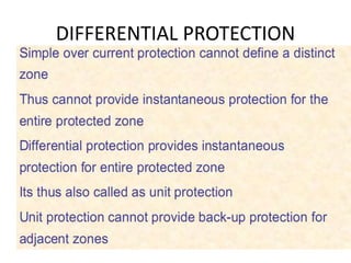
- 22. Limitations with OC Protection in Transformers • A simple overcurrent and earth fault relay will not provide adequate protection for winding earth faults. • Need some earth fault protection. • Degree of earth fault protection is very much improved by the application of unit differential or restricted earth fault systems.
- 23. Restricted Earth Fault Protection
- 24. Restricted Earth Fault - How it Works • On the HV side, the residual current of the 3 line CT’s is balanced against the output current of the CT in the neutral conductor. • For the LV side, earth faults occurring on the delta winding may also result in a level of fault current of less than full load. HV overcurrent relays will not provide adequate protection. • A relay connected to monitor residual current will provide restricted earth fault protection since the delta winding cannot supply zero-sequence current to the system.
- 25. Restricted Earth Fault - How it Works .. 2 • Both windings of the transformer can thus be protected separately with restricted earth fault. • Provide high speed protection against earth faults over the whole of the transformer windings. • Relay used is an instantaneous high impedance type.
- 26. High Impedance Differential Scheme
- 27. High Impedance Scheme - How it Works The CTs generate currents that create a high voltage across the relay (which has a high burden). CTs must generate 2 times the trip voltage to work on an internal fault If one only CT saturates for through fault, not enough voltage is generated to trip relay.
- 28. High Impedance Scheme - Requirements • CTs must have identical turns ratios, knee- point voltages 2 times relay operating voltage, high accuracy, low reactance (‘PX’ class) • High internal faults can generate high voltage across relay - some form of voltage dependent resistor (“metrosil”) is required to avoid this.
- 29. High Impedance Scheme - Relay Circuit Refer worked tutorial example on how the stabilising resistor value Rstab is calculated.
- 31. High Impedance Scheme - Example … 2
- 32. Feeder Differential Protection (Balanced Voltage) “Translay” protection Top - external fault, CT current balance, no net voltage across relays Bottom - internal fault, CT currents add, net voltage across both relays.