
Recommended
More Related Content
What's hot
What's hot (20)
Similar to 75181713.pdf
Similar to 75181713.pdf (20)
More from Thien Phan Bản
More from Thien Phan Bản (20)
Recently uploaded
Recently uploaded (20)
75181713.pdf
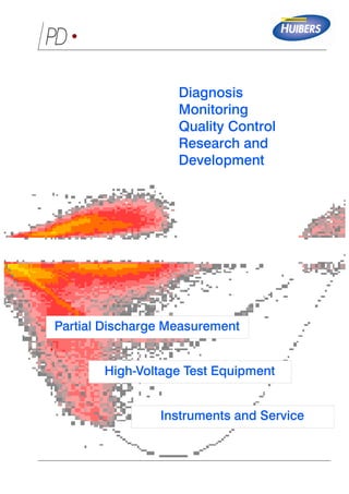
- 1. PD • Partial Discharge Measurement High-Voltage Test Equipment Instruments and Service Diagnosis Monitoring Quality Control Research and Development
- 2. PD • Power Diagnostix Systems GmbH provides quality instruments and engineering services for high-voltage diagnostic applications. Power Diagnostix has built a solid reputation since market introduction of our partial discharge detectors in early 1993. Our ICMseries of digital partial discharge detectors is used for evaluation of electrical insulation by electric utilities, manufacturers, and research institutes worldwide. In addition to digital partial discharge detectors, Power Diagnostix produces instrumentsforcommissioning tests of GIS systems, automated control of high-voltage tests, fiber optic connec- tions for analog signal transmission between instruments and sensors, and for other applications in high volt- age. All of our instruments and specialized software products are developed in Aachen, Germany. Agents worldwide work in direct contact with us and our customers to find optimized solutions for their applica- tions. The company's principal en- gineers are active in several scientific committees. Company Profile
- 3. Power Diagnostix Systems GmbH 1 PD • Power Diagnostix Systems GmbH produces versatile, top-quality instruments for high-voltage diagnostic applications. Power Diagnostix ICMseries of partial discharge (PD) detectors is used worldwide for evaluation of electrical insulation used in electricity generation, transmission and distribution, in manufacturing, in research, and in industry. In addition to partial discharge detection equipment, Power Diagnostix produces instruments for fiber optic transmission, GIS fault location, tand measurements, and high-voltage test control. Instruments ICMmonitor 13 The ICMmonitor is an instrument for continu- ous on-line monitoring of partial discharge activity in high voltage equipment. The in- strument tracks changes in key discharge quantities for storage in trending diagramsand for triggering user-settable alarms. TCP/IP, Modem, fiber optic or direct serial links enable remote access and full remote control. ICMcompact 11 The ICMcompact is a stand-alone partial discharge detector often used for quality as- surance. Among other options, the ICMcom- pact can be equipped with circuits to perform partial discharge location in power cables. ICMsystem 7 The ICMsystem is a digital partial discharge detection system. The instrument is com- pletely controlled by software using a GPIB, USB, TCP/IP, GSM Modem, fiber optic or direct serial link. ICMsys8 9 The ICMsys8 is a true-parallel 8-channel acquisition system, while offering all features of the single channel ICMsystem. It is de- signed for acceptance tests on large power transformers and other application requiring parallel acquisition.
- 4. Power Diagnostix Systems GmbH Vaalser Strasse 250 52074 Aachen Germany Email: support@pdix.com Web site: www.pdix.com Tel: + 49 241 74927 Fax: + 49 241 79521 2 PD • ã Power Diagnostix 2014 SPECcompact 15 The SPECcompact is a narrow- and broad- band partial discharge detector with select- able center frequency. The unit offers as well spectrum analysis up to 10 MHz and a selectable bandwidth of 9 kHz or 270 kHz. The SPECmonitor is a partial discharge analyzer comprising a spectrum analyzer, an acoustic detector, and a conventional partial discharge monitor in one instrument. SPECmonitor 19 The AIAcompact is a portable unit for acoustic and electric (UHF) partial discharge measurement on GIS, transformers, and cable accessories. Optionally, the unit can be equipped with circuits for UHF measure- ments. AIAcompact 17 The RIVmeter is an instrument for the measurement of 'Radio Influence Voltage' according to NEMA 107-1987 and other relevant standards. RIVmeter 21
- 5. Power Diagnostix Systems GmbH 3 PD • The ICMflex instrument family, introduced in 2008, bases on the latest concept where the entire acquisition hardware is placed on high voltage potential. The instruments are fully remote controlled via high speed Bluetooth or fiber optic communication. ICMflex 23 The TDAcompact is a loss factor meter. The capacitance Cx , the tand, and the voltage are derived by digitally processing the cur- rents of the test capacitor and a reference capacitor. TDAcompact 25 The STEPcompact allows running high volt- age test sequences. The instrument controls via fiber optic cable the 'UP' and 'DOWN' contact of the motor driven voltage regulator (VARIAC). The instrument detects incipient breakdown. STEPcompact 29 HVcompact 27 The HVcompact is a high voltage meter with an auto-ranging oscilloscope display of the voltage waveform. The unit displays Û, Û/Ö2, Urms , frequency, and crest factor. The HVcontrol offers all features that are required to manually control any high voltage test set. Current limits that trip the maincircuit breaker can be set for Iprim and Isec . HVcontrol 31
- 6. Power Diagnostix Systems GmbH Vaalser Strasse 250 52074 Aachen Germany Email: support@pdix.com Web site: www.pdix.com Tel: + 49 241 74927 Fax: + 49 241 79521 4 PD • ã Power Diagnostix 2014 The FOsystem is a complete set of instru- ments for fiber optic transmission of analog signals from different sensors (e. g. tempera- ture, pressure, acoustic, voltage, current).The signal bandwidth covers DC up to 10 MHz. FOsystem 33 The GISmonitor offers parallel, real-time ac- quisition of UHF PD signals captured by any embedded or external sensors permanently installed on gas-insulated switch gear (GIS). The system builds on compact 8-channel sub-modules to allow flexible configuration. GISmonitor 39 The ATTanalyzer supports commissioning of gas-insulated switchgear yards. Signals of up to 16 acoustic sensors can be con- nected. Precise localization of breakdown within the GIS is provided by comparing the travel-time of the breakdown sound to the various sensors. ATTanalyzer 37 We offer a variety of calibrators ranging from 1pC to 50 nC. Due to their high bandwidth the calibrators are suitable for impulse reflec- tometry on cable systems and for GIS testing. New charge calibrators are shipped with the DKD calibration certificate to ensure the trace- ability to international standards. Calibrators 41
- 7. Power Diagnostix Systems GmbH 5 PD • Coupling capacitors with built-in quadrupoles are used to capture the PD signals and to synchronize the measurement to the test frequency. Additionally, rugged coupling ca- pacitors are used for permanent installation for monitoring purpose. Coupling Devices & Filters 49 When a quadrupole and a coupling capacitor are used together as the coupling device, high voltage is applied both to a test object and to the coupling capacitor in parallel with the test object. A quadrupole (sometimes called a measuring impedance) can then be placed in series with either the coupling capacitor or in series with the test object. Preamplifiers serve to condition, filter, and amplify the PD signal to be measured. Preamplifiers & Measuring Impedances 45 We offer various sensors for temporary or permanent installation with gas-insulated switchgear (GIS), cable accessories, and power transformer. This includes several sensor models to capture UHF signals. Sensors 51 On-site transformer testing is the main ap- plication of Power Diagnostix' mobile high voltage AC test system. However, it can be used as well for other on-site testing, such as of GIS, rotating machines, or high volt- age cables. Mobile HV AC Test System 43
- 8. Power Diagnostix Systems GmbH Vaalser Strasse 250 52074 Aachen Germany Email: support@pdix.com Web site: www.pdix.com Tel: + 49 241 74927 Fax: + 49 241 79521 6 PD • ã Power Diagnostix 2014 Typical PD Pattern 69 With the PD pattern (j-q-n pattern), each acquired impulse is sorted and counted with respect to its phase angle and acquired amplitude. The pattern contains information of various properties of the defect causing the discharge. We offer on- and off-line PD analysis on ro- tating machines, transformers, cables, etc. Instruments can be provided temporarily on a rental base. Furthermore, an on-site DKD- calibration of HVAC measurement systems up to 100 kV can be performed. Services 67 Using the range of instruments with the differ- ent applications, such as rotating machines, power transformers, cable systems, or GIS and GIL, requires considering the special conditions of each field. Applications 57 Miscellaneous accessories are available for the ICMseries instruments such as bushing adapters, bushing coupling units, current transformers, and various antenna models. Each ICMseries acquisition unit can be com- bined with these accessories to suit specific applications. Miscellaneous 53
- 9. Power Diagnostix Systems GmbH PD • 7 The ICMsystem is part of the Power Diagnostix ICMseries of digital partial dis- charge detectors. The ICMsystem is a powerful, versatile instrument for evaluating the condition of medium and high voltage insulation. The ICMsystem is usable over a range of frequencies of applied voltage, including power system frequency (50/60 Hz) and VLF (0.1 Hz). Partial discharge (PD) measurements are a proven method for effective, non- destructive evaluation of electrical insu- lation. The Power Diagnostix ICMsystem provides high-resolution digital PD pat- terns for characterization of defects in high voltage insulation systems. Versatility The key to the versatility of the ICMsys- tem is its modular design. The ICMsys- tem can be matched up with a variety of special accessories that adapt it to virtually any high-voltage testing environ- ment.Awide range of external preampli- fiers provides control of the frequency range in which PD activity is detected, from 40 kHz up to 2 GHz. Phase-resolved PD pattern ICMsystem The key to the versatility of the ICMsystem is its modular design. Assorted coupling devices, including quadrupoles, coupling capacitors, and current transformers, are available to sense the PD signal in the object under test. Like the other instruments in the ICMseries, the ICMsystem provides effective noise gating that blocks phase- stable noise as well as noise indepen- dent of the applied voltage cycle, allow- ing the ICMsystem to be used in noisy environments without losing significant PD data. Appropriate selection of a pre- amplifier can assist further in achieving a high signal-to-noise ratio. PC Software The operating parameters of the ICM- system are fully computer controlled, making it simple to use with standard Power Diagnostix software. The actual recording of PD patterns is independent of the PC, so the performance of the ICMsystem is unaffected by speed limi- tations of the PC or communications.
- 10. Power Diagnostix Systems GmbH Vaalser Strasse 250 52074 Aachen Germany Email: support@pdix.com Web site: www.pdix.com Tel: + 49 241 74927 Fax: + 49 241 79521 ã Power Diagnostix 2014 PD • 8 Giving users complete access to detailed control parameters and the ability to download and analyze PD patterns on a PC makes the ICMsystem the ideal instrument for advanced analysis of phase-resolved partial discharge patterns, whether in research, utility, or industrial applications. The ICMsystem’s PC software in- cludes convenient options for in-depth analysis and printing of stored PD patterns. Special Applications and Options For applications such as DC test- ing or stepped high-voltage testing, the ICMsystem allows recording PD activity versus time (sequentially) instead of versus phase angle. Op- tions such as a multiplexer module, fiber optic bus, and built-in modem further extend the capabilities of the ICMsystem. The multiplexer module, working with ICMmux software, allows easy selection among eight channels for PD measurement. The fiber optic bus provides enhanced protection in hazardous measurement conditions and can link widely separated com- ponents of a test setup. The modem option permits remote access to data and control of the ICMsystem. The full command set of the ICMsystem is provided with the device also, so users may create custom programs to control the ICMsystem for highly specialized applications or for integra- tion into an overall high-voltage test control program. Options: • Multiplexer • Built-in spectrum analyzer • RIV measurement • Cable fault location • Acoustic PD location
- 11. Power Diagnostix Systems GmbH PD • 9 ICMsys8 The ICMsys8 is specifically designed to meet the requirements of partial discharge acceptance tests on large power transformers. The instrument builds on the ac- quisition core of the standard ICMsystem. However, by introducing an individual amplifier plug-in for each channel, true parallel acquisition of the discharge magni- tude of eight channels is achieved. The instrument can be equipped with optional features like RIV or acoustic PD measurement. Using the eight-channel ICMsys8 greatly simplifies partial discharge acceptance tests on large power transformers. With the true parallel acquisition of the partial discharge activity on eight channels, the overall testing period is substantially shortened. Independent Channels For each of the eight partial discharge measurement channels an independent quadrupole, pre-amplifier, and amplifier plug-in is provided. Internally, the sys- tem controller processes the discharge readings acquired for each channel in a true bipolar peak amplitude acquisi- tion. Optionally, the PD readings can be weighted according to IEC60270-2000. Besides the eight partial discharge chan- nels, the instrument offers eight inde- pendent channels for the measurement and sampling of the AC voltage signal provided by the quadrupole. Pattern Acquisition In addition to the parallel acquisition of the PD activity for the meter and strip- chart displays, the pattern acquisition core known from the standard ICMsys- tem offers the defect identification ca- pabilities of the phase-resolved partial discharge analysis. The influence of power frequency harmonics on the PD pattern, often found with power trans- formers, can be clearly identified, as the waveform of the AC voltage is available for each channel. Software The control software to run the eight- channel ICMsys8 offers manual and au- tomatic modes for the acceptance test. Typical test sequence for HV transformer True eight-channel partial dis- charge acquisition
- 12. Power Diagnostix Systems GmbH Vaalser Strasse 250 52074 Aachen Germany Email: support@pdix.com Web site: www.pdix.com Tel: + 49 241 74927 Fax: + 49 241 79521 ã Power Diagnostix 2014 PD • 10 ICMsys8 installed in a control room The ICMsys8 for power transformer acceptance testing is the first commer- cially available partial discharge detector with true parallel acquisition on eight channels. The ICMsys8 and its software greatly simplify the testing procedures and, thus, reduce the time the transformer needs to stay in the Reporting is simplified with MS Word and plain text output formats. The reports are based on user-selectable templates. In acceptance test mode, the software shows eight meter displays, each indi- cating PD level, voltage, and frequency of the specific channel. With the center display, the automatically or manually triggered values are presented in list mode or as a strip-chart. Further, dur- ing calibration, the cross-coupling ma- trix between the channels is built up, which eventually can help locating the source of PD activity. Additionally, the ICMsys8 software provides the user with all the features known from the standard ICMsystem, such as multi- channel consecutive pattern acquisi- tion, movie-like replay, or statistical evaluation, for instance.
- 13. Power Diagnostix Systems GmbH PD • 11 The ICMcompact is part of the Power Diagnostix ICMseries of digital partial discharge detectors. The ICMcompact is a compact, stand-alone instrument for evaluating the condition of medium and high voltage insulation. It is often used in quality assurance and quality control tests in manufacturing. Stand-Alone Instrument Partial discharge (PD) measurements are a proven method for effective, nondestructive evaluation of electrical insulation. The Power Diagnostix IC- Mcompact provides a simple push-but- ton interface and on-screen menus in an embedded LCD panel. The LCD display modes include a simple PD charge meter with adjustable “needle” sensitiv- ity, monochrome phase-resolved PD patterns for characterization of defects, and a scope-like display showing phase- summed charge pulses superimposed with the applied voltage wave. Phase-resolved PD pattern ICMcompact Although the ICMcompact is an autono- mous unit, it can be connected to a com- puter installed with Power Diagnostix software to capture screenshots or to implement remote control of the unit. Applications Instantly displaying information in an intuitive interface, the ICMcompact is a good choice for applications such as quality control tests in manufacture of electrical products, and for quality as- surance of industrial and utility equip- ment from capacitors and bushings to gas-insulated switchgear and others. A wide range of accessories adapts the ICMcompact to specific testing applica- tions and noise conditions. The ICMcompact equipped with an optional DSO board can be used to lo- cate partial discharge defects in power cable. Using time domain reflectometry, in which the PD and its “echoes” travel the length of the cable under test, the ICMcompact provides the proportional distance of the PD fault along the cable.
- 14. Power Diagnostix Systems GmbH Vaalser Strasse 250 52074 Aachen Germany Email: support@pdix.com Web site: www.pdix.com Tel: + 49 241 74927 Fax: + 49 241 79521 ã Power Diagnostix 2014 PD • 12 The easy portability, simple operation, and flexibility of the Power Diagnostix ICMcompact make it a good choice for routine PD testing in a variety of utility and industrial applications. The ICMcompact offers convenient on- site testing of equipment such as cable accessories or sensors installed with gas insulated switchgear, for instance. Generally, this unit can be used with the full range of the ICMseries pre- amplifiers, covering the IEC60270 standard frequencies. To adapt the basic ICMcompact unit to suit special measurement require- ments, it can be equipped with various options: • Voltage measurement. Adds the HVM oscilloscopic display showing the waveform of the high voltage and calculates Û, Û/Ö2, Urms , etc. • Cable PD location. An additional DSO board samples the PD signal at 100 Msample. • Analog gating to cancel external distur- bance. This option offers sensitive mea- surements even in noisy environments. • TTL-Gating. Unconditioned gating on an external TTL signal to combine the ICMcompact with IGBT driven resonant high voltage test sets. • MUX4. Four-channel multiplexer for testing three-phase equipment, such as power transformers. For each channel the unit maintains an individual setup and calibration. • MUX12. With this option a remote 12-channel switching box offers cost- efficient acceptance testing on large power trans- formers. • AUX8. For long-term test- ing up to eight additional pa- rameters can be captured as 0(4)-20 mA or 0-10 V signals.
- 15. Power Diagnostix Systems GmbH PD • 13 ICMmonitor The ICMmonitor is part of the Power Diagnostix ICMseries of digital partial discharge detectors. The ICMmonitor is a compact, stand-alone instrument for evaluating the condition of medium and high voltage insulation. A built-in four-, or eight-channel multiplexer offers scanning of three-phase systems or multiple sensors. It is used principally for permanent, continuous on-line monitoring of rotating machines, cable systems, power transformers, and gas-insulated switch gear (GIS). Partial discharge (PD) measurements are a proven method for effective, non- destructive evaluation of electrical insu- lation, preventing expensive unplanned outages by detecting insulation problems before they can cause breakdowns. The Power Diagnostix ICMmonitor is a non-invasive digital PD detector for permanent installation and continuous monitoring of medium and high-voltage insulation. display for characterization of defects, a scope-like display showing phase- summed charge pulses superimposed with the applied voltage wave, a time trending display, and a monitoring dis- play showing bar graphs of two key par- tial discharge quantities (Qp and NQS). Qp is the apparent charge value of the PD activity, and NQS is the absolute discharge current obtained by integrat- ing the discharge values (summing up the total charge moved and dividing by the time interval, Q/t = [As]/[s]). Noise Rejection The ICMmonitor features various noise handling techniques. The noise gating module can be connected to an antenna or a current transformer to sense and remove noise without losing significant PD data. Another method available is simple windowing, that supresses phase-stable noise for certain portions of each applied high voltage wave. Additionally, appropriate choice of the external preamplifier can limit noise by detecting PD in a frequency band outside the range of the noise. Monochrome PD pattern display Embedded Display The ICMmonitor has a simple push- button interface to navigate on-screen menus in an embedded LCD panel. The LCD display modes include a mono- chrome phase-resolved PD pattern
- 16. Power Diagnostix Systems GmbH Vaalser Strasse 250 52074 Aachen Germany Email: support@pdix.com Web site: www.pdix.com Tel: + 49 241 74927 Fax: + 49 241 79521 ã Power Diagnostix 2014 PD • 14 The multifunctional ICMmonitor, with its embedded display, convenient trend- ing, and settable alarms, is an ideal solution for continuous on-line monitor- ing of rotating machines and other electric devices in industrial and utility applications. Alarms and Trending Users can set alarm levels of NQS or Qp that will trigger when those values are exceeded. A triggered alarm will sound, appear on the LCD display, and activate an output on the ICMmonitor that can be used to drive a relay for interfacing with a local alarm system. The ICMmonitor also collects and displays PD data over a specified time interval for easy trending and obser- vations of changes in the Qp and NQS levels in the monitored system. Option- ally, up to eight DC signals such as temperature or load can be added to this trending. Telemonitoring Although the ICMmonitor is an au- tonomous unit, it can be connected to download data or to implement remote control of the unit. With its built-in TCP/IP interface or analog modem, the ICMmonitor can be controlled and observed remotely over a telephone or Internet connection anywhere in the world. Optionally, if a monitored system exceeds an alarm level set by the user, the ICMmonitor can place a call to a user-selected number. The ICMmonitor software automatically maintains the trending information as well as the phase-resolved pattern of a multitude of ICMmonitor units. Portable ICMmonitor with modem
- 17. Power Diagnostix Systems GmbH PD • 15 SPECcompact The SPECcompact comprises a spectrum analyzer, a partial discharge (PD) detec- tor and an RIV meter in one instrument. This combination enables PD measure- ments even with a large background noise e.g. in non-shielded test areas. Measuring partial discharge within noisy environment Observing the frequency spectrum of a harshly disturbed PD signal allows selecting frequency bands with less disturbances. Using this selected fre- quency for a PD acquisition gives a largely improved signal-to-noise ratio resulting in a clear pattern acquisition. The combination of spectrum analyzer and PD detector within one instrument opens a broad field of new possibilities when analyzing isolation defects even with large noise. There are three main display modes and a high voltage meter (HVM) as optional function: SPEC Mode The SPEC mode shows the frequency spectrum of the input signal with a se- lectable span of up to 10 MHz. Three spectrum traces of the current input channel can be stored, compared and analyzed.Avariable cursor serves to set the center frequency for the PD pattern acquisition. The SPECcompact comes with one, three or eleven channels. A multiplexer allows to directly select the input signal. Spectrum scan display Frequency spectrum SCOPE Mode The SCOPE mode displays the PD pat- tern versus phase as known from the IC- Mseries. The SYNC frequency ranges from 10 to 500 Hz. The PD activity can be shown as vertical bars or as dots to get a so called PD pattern.
- 18. Power Diagnostix Systems GmbH Vaalser Strasse 250 52074 Aachen Germany Email: support@pdix.com Web site: www.pdix.com Tel: + 49 241 74927 Fax: + 49 241 79521 ã Power Diagnostix 2014 PD • 16 frequency harmonics, for instance, are clearly identified with this display. The screen is automatically synchro- nized with the measured voltage and the amplitude deflection is controlled by an auto-range function. SCOPE mode (NORM) METER mode (RIV & HVM) HVM mode The SPECcompact comprises a spectrum analyzer, a partial discharge (PD) detector and an RIV meter in one instrument. This combination enables PD measurements even with a large background noise e.g. in non-shielded test areas. METER Mode The METER mode can be chosen to visualize the PD activity like older analog meters. Three modes are available for the charge value in ‘pC’ (FAST, NORM, IEC270) and one for the voltage value in ‘µV’ (RIV). HVM Mode The high voltage meter (HVM) is an optional function to observe the mea- sured voltage waveform. The HVM shows the voltage supplied at the SYNC input. The input voltage is sam- pled in high resolution and one cycle is displayed as an oscilloscopic trace. Any distortion of the high voltage due to transformer core saturation or power SCOPE mode (HOLD) Accessories for RIV measurement
- 19. Power Diagnostix Systems GmbH PD • 17 AIAcompact TheAIAcompact is a portable unit for in-service acoustic and electric (UHF) partial discharge measurements on gas-insulated switchgear (GIS), transformers, and cable accessories. The instrument is fitted with a battery pack for independent operation up to 3 hours and adapts to a variety of piezo-electric acoustic sensors and is supplied with a versatile sensor fixture. Additionally, the AIAcompact allows partial discharge measurements on external UHF sensors. Acoustic partial discharge measurements can be easily applied on gas-insulated switchgear and other high voltage equip- ment without the need of interrupting the operation. Such onlinemeasurementshelp toidentifyinternalimperfectionsoftheinsula- tion system, which may lead to breakdown and system failure in the future. Acoustic partial discharge measurements rely on the close acoustic contact of the area producing the discharge to the point of access,wherethesensorisplaced.Mostof thepartialdischargeactivityinGISoffersuch agoodcontactand,hence,canbedetected at a good sensitivity. Therefore, discharges from sharp points or cones as well as discharge activity from delaminations can be identified at a sen- sitivity, which is mostly comparable to the conventional electrical detection according to the IEC60270. Forsomedefecttypes,suchastheso-called hopping or bouncing particles, the acoustic detection is by far superior to the electrical detection. Based on the proven hardware core of the ICMcompact, the AIAcompact offers auto- maticdetectionofthesensororpreamplifier used. Normally, the instrument is operated with acoustic sensors with remote supplied embeddedpre-amplifiersdirectlyconnected to the signal input. Alternatively, the RPA1F can be inserted close to the sensorto boost the signal, in case longer signal cables are used or in case of low-level measure- ments. UHF measurements on external sensors are possible with the use of the FCU2, a logarithmicfrequencyconverter,which cov- ers 300 MHz-2 GHz. As with the pre-ampli- fiers, the AIAcompact automatically detects the FCU2 and changes into the logarithmic displayfortheUHFdetection.Toprotectthe instrument's hardware an input protection unit like IPU2B can be connected to the sensor's output. The instrument offers three display modes, which are selected using dedicated control buttons: SCOPE, METER, and TIME. SCOPE In SCOPE mode, theAIAcompact shows the phase-resolved partial discharge sig- nal or pattern. Here, the 'Freeze' function Easy-to-apply substation condition assessment
- 20. Power Diagnostix Systems GmbH Vaalser Strasse 250 52074 Aachen Germany Email: support@pdix.com Web site: www.pdix.com Tel: + 49 241 74927 Fax: + 49 241 79521 ã Power Diagnostix 2014 PD • 18 Offering easy-to-use acoustic partial discharge analysis of gas-insulated switch- gear (GIS) and other high voltage equipment plus the optional analysis on em- bedded or external UHF sensors makes the AIAcompact the ideal solution for convenient in-service substation condition assessment. allows keeping such a captured pat- tern for further evaluation or for taking screen-shots. METER The METER mode offers four bar graph displays showing derived quantities of the captured activity. The graphs display the RMS and the peak PD level, as well as their 50 Hz (60 Hz) and 100 Hz (120 Hz) content. The in- strument automatically synchronizes to the line frequency. TIME Within the TIME mode, the AIAcom- pact displays five or ten AC cycles triggered by a partial discharge event. Thus, this display shows the pattern of consecutive partial discharge events and, hence, offers a clear identification of bouncing particles and the severity of their activity. Options - AIAcompact software: All captured patterns and displays can be trans- ferred to a notebook via an USB in- terface using the optionalAIAcompact software. Optionally, the software allows acquisition of color PD pat- terns. - Gating: Software controlled noise reduction for PD measurements in environments with high frequency disturbance. - MUX: Built-in 4- or 12-channel mul- tiplexer to split the PD signal and the voltage signal, with individual setup and calibration factor for each chan- nel. - 57kB modem: A built-in analog mo- dem allows to access theAIAcompact via a common phone line. SCOPE display METER display TIME display FCU2 & IPU2B RPA1F & AS75I DA2
- 21. Power Diagnostix Systems GmbH PD • 19 The SPECmonitor is a partial discharge (PD) measurement device comprising a spectrum analyzer, an acoustic detector, and a conventional PD monitor in one instrument. This combination enables PD measurements even with high levels of background noise e.g. on power transformer within substations or power plants. Observing the frequency spectrum of a harshly disturbed PD signal allows to select frequency bands with less disturbances. Using this center frequency for a PD acquisition, gives a largely improved signal-to-noise ratio resulting in a clear pattern acquisition. The combination of spectrum analyzer and PD detector within one instrument greatly expands the measurement possibilities when analyzing the insulation systems in a noisy environment. In the standard version, the SPECmonitor comes with an eight or four channel mul- tiplexer to directly select the input signal. The instrument provides five different display modes and several interfaces like e.g. TCP/IP or modem for remote control and diagnosis. SPEC Mode The SPEC mode shows the frequency spectrum of the input signal up to 10 MHz. Three traces for the current input channel allow storing, comparing and processing of this spectrum. The bandwidth of the demodulated signal can be set to 9 kHz or 270 kHz, respectively. SCOPE Mode The SCOPE mode displays the PD pattern versus phase as known from the ICMseries. Hereby, the selected center frequency and bandwidth of the SPEC mode is used, in order to disre- gard frequency ranges occupied with disturbances. The SCOPE mode offers viewing an oscilloscopic display (below) as well as a pattern display. SPECmonitor Measuring partial discharge within noisy environment Scope display
- 22. Power Diagnostix Systems GmbH Vaalser Strasse 250 52074 Aachen Germany Email: support@pdix.com Web site: www.pdix.com Tel: + 49 241 74927 Fax: + 49 241 79521 ã Power Diagnostix 2014 PD • 20 Monitoring display Spectrum display Trending display SPECmonitor in a full 19'' rack Combining a spectrum analyzer and the multifunctional ICMmonitor greatly expands the measurement possibilities of the SPECmonitor. This combination allows PD monitoring even with a large background noise and with different sensors connected. Acoustic sensor with magnetic holder Bushing adapter and coupling unit MON Mode The monitoring display allows to set alarm levels of NQS or Qp that will trig- ger when those values are exceeded. TIME Mode Additionally, the SPECmonitor collects and displays PD data over a specified time interval for easy trending and ob- servations of changes in the Qp and NQS levels of the monitored system. Software Besides this autonomous functions, the instrument can be connected to a computer via serial interface, modem, or TCP/IP. A special software allows the remote control of the instrument and the download of the stored data. An autoscan function takes the trend- ing information as well as the phase- resolved pattern of one or multiple units. Accessories It is possible to connect acoustic sen- sors (AS), UHF sensors, or the stan- dard coupling unit from the bushing test tap to the SPECmonitor. SPECmonitor software Different preamplifiers like RPA1F, RPA1L or FCU2 can be used in case of weak signals or to drive long cable lengths. Principle connection diagram
- 23. Power Diagnostix Systems GmbH PD • 21 RIVmeter The RIVmeter is an instrument for the measurement of radio influence voltage (RIV) according to the relevant standards (NEMA107-1987, IEC CISPR 18-2:2010, EANSI 63-2-1996, VDE 876, DIN EN 55016-1-1). The instrument has a bandwidth of 9 kHz and a tunable center frequency of 100 kHz to 2 MHz. Technically, the RIVmeter is a selective µV-meter. However, the meter reading is weighted ac- cording to the CISPR weighting curve, whereas the repetition rate has a strong impact on the reading. The RIVmeter is an ideal instrument to replace outdated RIV measurement instruments in a transformer testing lab, for instance. Some routine PD measurements are still done according to IEEE standards requiring the measurement of radio influ- ence voltage. The RIV value is given in µV (interference voltage).Anarrow band filter performs a quasi-integration of the PD pulses with a quasi-peak detection at the center frequency. This center frequency can be adjusted between 100 kHz and 2 MHz. The narrow-band pass filter allows to suppress external noise e. g. in non-shielded laboratories by varying the center frequency of the filter. Two factors determine the RIV in µV: the transferred charge and the repeti- tion rate of the PD impulse (number of PD pulses per second). Because of this proceeding, a direct translation of the measured RIV values (µV) into values of apparent charge in pC is not possible. Historically, the RIV technique is based on measurement receivers to estimate the disturbance of communication lines. Thus, properties of those instruments then available became part of the NEMA standards. However, both the 9 kHz bandwidth and the CISPR weighting curve put emphasis on some partial discharge activity, while they tend hid- ing others. New RIVmeter supporting old standards
- 24. Power Diagnostix Systems GmbH Vaalser Strasse 250 52074 Aachen Germany Email: support@pdix.com Web site: www.pdix.com Tel: + 49 241 74927 Fax: + 49 241 79521 ã Power Diagnostix 2014 PD • 22 Old Siemens B83600-B40 The calibration of the RIV measure- ment is done using an RIV calibra- tor, injecting a sine wave of typically 100 µV into the bushing. The mul- tiplexer of the RIVmeter is used to conveniently determine the correction factor according to NEMA 107-1987 and other standards. Here, the unit compares the voltage injected, i. e., loaded by the bushing’s impedance, with the voltage detected at the bush- ing tap to automatically determine the k-factor. This correction factor is then stored independently for each chan- RIVmeter rear panel CAL3A and CAL3D The RIVmeter is an instrument for the measurement of radio influence volt- age according to NEMA 107-1987, IEC CISPR 18-2:2010, and other relevant standards. It is the ideal instrument to replace outdated RIV measurement instruments in a transformer testing lab. Old Stoddart NM-25T nel during calibration. The standard calibrator for RIV calibration, CAL3A, offers a selectable frequency range of 600-1350 kHz in steps of 50 kHz. The output voltage covers 10 µV to 10 mV in 1-2-5 steps. The CAL3B calibrator offers a frequency range of 400 kHz to 1.9 MHz with the same output voltage but in steps of 100 kHz. Having the same frequency range as the CAL3B, the CAL3D comes in contrast with a high impedance output (> 20 kΩ) ac- cording to IEC CISPR 18.2:2010. NEMA compliant test set-up
- 25. Power Diagnostix Systems GmbH PD • 23 ICMflex The ICMflex high voltage instrument family offers inherent operator safety and greatly simplifies distribution class cable testing and other field tasks involving partial discharge and tand testing. With the unique concept of the ICMflex instru- ments, the entire acquisition hardware is placed on high voltage potential right at the position where the signals are. Thus, no signal cables are needed, as the instrument is fully self-contained and battery operated. The instruments are fully remote controlled via high speed Bluetooth or fiber optic communication. Unique Concept The ICMflex instrument family is avail- able with different options and for dif- ferent voltage levels. Additionally, the self-contained ICMflex acquisition unit can be placed on top of any third-party coupling or reference capacitor. The op- tion TD offers tand and power factor (PF) measurements. The option PD provides partial discharge measurements accord- ing to the IEC60270, whereas the option PDL includes partial discharge location for power cables. Finally, the option TF covers a high voltage T-filter to sufficiently de-noise a high voltage supply for sensitive partial discharge measurements. The detach- able Li-MH battery provides 10 hours of continuous operation, while a second battery is charged. Any high voltage AC Wireless signal transmission via Bluetooth communication source can be used including resonant test sets and VLF high voltage sources. Testing distribution-class cables in a field environment becomes an easy and inherently safe task. The ICMflex unit is simply placed between high voltage source and the cable to be tested – no further leads required. The ICMflex unit can be equipped with a high voltage fil- ter to accommodate noisy high voltage sources. Thus, with one unit requiring only high voltage and ground connec- tion all essential measurements on laid power cable are performed in one step: tand, partial discharge, and partial dis- charge location. Off-line testing of generator and motor stator coils is simplified in the same way. Using any high voltage source, the criti- cal AC measurements on the stator coil are done simultaneously: tand, PF, and partial discharge.
- 26. Power Diagnostix Systems GmbH Vaalser Strasse 250 52074 Aachen Germany Email: support@pdix.com Web site: www.pdix.com Tel: + 49 241 74927 Fax: + 49 241 79521 ã Power Diagnostix 2014 PD • 24 Using wireless Bluetooth or fiber optic technology the ICMflex tand and partial discharge analyzer family increases operator’s safety and greatly simplifies off-line testing and analysis of distribution class cables and rotating machine stator windings. Option TD The tan delta analyzer uses an unbal- anced bridge formed by internal shunt capacitors, the reference capacitor and the device under test. Here, the ICMflex software shows tand, PF, ca- pacitance, voltage, and frequency. Option PD With the option PD the ICMflex soft- ware offers a meter display according to IEC60270 and an oscilloscopic display of the partial discharge activ- ity as well as a colored j-q-n pattern (above) based on the data received via Bluetooth. Placing the quadrupole and acquisition unit on high voltage potential greatly improves the sensi- tivity and avoids any noise pickup on signal cables. Option LOC The partial discharge location op- tion uses high speed (100 Msample) sampling of the PD pulses traveling the cable.Along with the analog band- width of 20 MHz this enables precise location and mapping of the discharge activity along the cable. ICMflex software ICMflex & HV filter On-site cable testing TD measurement on motor bars
- 27. Power Diagnostix Systems GmbH PD • 25 TDAcompact The TDAcompact is a portable capacitance and tand analyzer. The focus of the instrument's application is on the analysis of the epoxy-mica insulation of rotating machines. Besides this, the unit is applicable for oil-paper insulation systems and especially for mass-impregnated cables. Analyzing the dissipation factor (tand) is a traditional method to assess the condition of an insulation system. With the analysis of the dissipation factor, em- phasis is more put on the overall health of the insulation system, whereas with partial discharge analysis, the focus is on individual defects producing discharge activity. Therefore, the application of tand measurements concentrates on insulation systems, which are relatively stable against partial discharge. Most prominently, the health of an epoxy-mica insulation of a rotating machine can be assessed using a tand analyzer. Especially, the presence of humidity within the winding, the surface contamination of field grading elements, or the polarization losses of improperly cured resin, can be detected. Thus, the tand analysis is still a good complement to the partial discharge testing. Dissipation factor Principle of Operation The TDAcompact simultaneously sam- ples theAC current drawn by the device under test and the current drawn by a reference capacitor. Subsequently, the two current traces are evaluated and the capacitance, the tand, and the level of the high voltage are calculated. The unit continuously displays and refreshes these results. Portable and accurate tand analysis
- 28. Power Diagnostix Systems GmbH Vaalser Strasse 250 52074 Aachen Germany Email: support@pdix.com Web site: www.pdix.com Tel: + 49 241 74927 Fax: + 49 241 79521 ã Power Diagnostix 2014 PD • 26 Offering adequate resolution and accuracy as well as an unmatched porta- bility, the TDAcompact is an excellent choice for field-type dissipation factor measurements. Additionally, the TDAcompact can be used as a module of a flexible automated test system. Therefore, the instrument does not require any user interaction as with the traditional Schering Bridge, nor does the refresh of the display take that long as with automatic adjust- ing bridge-type analyzers. The basic resolution of the tand measurement is 10-4 , which fulfills the requirements for rotating machine testing as well as for testing on mass-impregnated cables. Stand-alone Instrument The TDAcompact is designed as a stand-alone instrument. To measure the two currents the basic configura- tion of the TDAcompact comes with a standard capacitor, that has a built-in shunt capacitor, in combination with an external shunt. Optionally, the unit can be supplied with further shunt capacitors. Generally, the TDAcompact is with digital fiber-optic links to the precision shunts, which allow operation on any potential including the high voltage connection of the device under test. The measuring frequency can vary between 20 and 500 Hz or is fixed to 0.1 Hz (VLF). Upon request, Power Diagnostix can supply complete por- table tand testers including the high voltage transformer. Modular Concept Besides the stand-alone field test application of the TDAcompact, the instrument can also become a part of a larger and automated test system. Using the software HVpilot, the instru- ment will be read according to a pre- programmed test sequence. Besides tand measurements, such automated test systems further include partial discharge measurements and so- called step tests.
- 29. Power Diagnostix Systems GmbH PD • 27 The HVcompact is a high voltage meter with an auto-ranging oscilloscope display of the voltage waveform. The unit displays Û, Û/Ö2, Urms , frequency, and the crest factor. To improve the readability, one selected measurement is displayed using larger characters. To protect test specimens, the unit offers a pre-settable voltage limit, which trips a relay output. The divider ratio is widely adjustable and is kept with a non-volatile memory. HVcompact ics, for instance, are clearly identified with this display. The screen is automati- cally synchronized with the measured voltage and the amplitude deflection is controlled by an auto-range function. Mostly, the HVcompact is used in case of modernization or upgrade of high volt- age test sets. With conventional analog or digital panel meters, usually, solely the voltage is displayed. The HVcompact adds several helpful functions. Oscilloscopic Display The input voltage is sampled in high resolution and one cycle is displayed as an oscilloscopic trace. Any distortion of the high voltage due to transformer core saturation or power frequency harmon- Measurements Usually, the instrument connects to capacitive or resistive divider. With larger high voltage transformers, the capacitance of the condenser bushing can be used. Within the menu of the HVcompact the divider ratio can be adjusted. It is kept with a non-volatile memory. The nominal input range of the HVcompact is 100 Vrms . In order to cover correctly even strong harmonics, peak voltages of up to 200 V are accepted and sampled. Scope display of the waveform All voltage information at a glance
- 30. Power Diagnostix Systems GmbH Vaalser Strasse 250 52074 Aachen Germany Email: support@pdix.com Web site: www.pdix.com Tel: + 49 241 74927 Fax: + 49 241 79521 ã Power Diagnostix 2014 PD • 28 Using the sampled voltage, the instru- ment calculates based on the preset divider ratio the characteristic quanti- ties of the high voltage signal. With the upper two lines of the display the peak voltage Û, the peak voltage divided by the square root of two Û/√2, and the effective voltage Urms is shown. Addi- tionally, the crest factor is calculated and displayed. With the bottom line of the display, the frequency of the captured voltage signal is shown. This bottom line further shows the scaling of the Y-axis grid of the oscilloscopic dis- play. One selected value is displayed using larger characters for improved readability. Safety Features A voltage limit can be set with the in- strument in order to avoid that a test specimen is stressed above its allow- able voltage. In case the voltage then exceeds this limit, a relay is tripped. This relay can be used to block the 'UP' button of the control circuit or to disconnect the main circuit breaker. Additionally, the instrument detects in- cipient breakdown or flashover. There- fore, a maximum permissible voltage change per second (dU/dt) can be set. Each individual cycle of the high volt- age signal is analyzed. Especially with long-term voltage endurance tests, this feature can minimize the thermal destruction of the breakdown channel and, thus, improves the analysis of the defect. Optional REC OUT The HVcompact is available with an optional recorder output. In case, a connector carries a re-converted analog (DC) signal of 0-10 V, which corresponds to the high voltage signal. This signal can be fed to a paper recorder, for instance. A screw terminal carries the optional relay output signals for voltage limit and breakdown detection. Giving an instant display of all relevant parameters of a high voltage signal including an oscilloscope trace makes the HVcompact an ideal upgrade for high voltage test rooms. Additionally, the HVcompact detects incipient break- down and keeps a record of the voltage history. By end of 2003, Power Diagnostix received the accreditation as calibration By end of 2003, Power Diagnostix received the accreditation as calibration laboratory within the German Calibration Service (Deutscher Kalibrierdienst, DKD). The audit was held by 'Physikalisch Technische Bundes-anstalt' PTB, the German authority of standards. In 2006, Power Diagnostix extended the accreditation by AC high-voltages up to 100 kV. On order the HVcompact can be calibrated on site together with its divider impedance. In January 2012, Power Diagnostix passed over to the newly introduced German accreditation authority DAkkS (DAkkS = Deutsche Akkreditierungs- stelle). Power Diagnostix’ accredita- tion is filed under D-K-15068-01-00. Calibration 11030006-01 D-K- 15068-01-00 2013-04
- 31. Power Diagnostix Systems GmbH PD • 29 STEPcompact Increasing the high voltage stepwise is a task that is often required during type testing and production testing of high voltage products. The STEPcompact is an instrument to automate such step tests. The unit combines the control function with the measurement capabilities of a high voltage meter. As a stand-alone in- strument, the STEPcompact can be easily moved between different high voltage test sets. Running step test sequence The STEPcompact measures the voltage signal derived from a capacitive or resis- tive divider. Using a fiber optic transmis- sion, the UP and DOWN relay contacts of the voltage regulator are actuated to adjust the high voltage according to the programmed test sequence. Features Similar to the HVcompact, the instrument calculates and displays the characteris- tics of the captured high voltage signal such as Û, Û/Ö2, Urms , frequency, and the crest factor. The unit accepts a nominal input voltage of 100 Vrms . In order to cor- rectly acquire even excessively distorted high voltage signals, the STEPcompact samples up to 200 V peak signals. Using the five menu-driven control but- tons, up to 35 different test sequences can be programmed and stored in a non-volatile memory. A test sequence consists of steps and ramps in any order. Besides the automatic mode, a manual mode can be used to set a specific voltage and keep it over time. In factory environments with strongly varying load situations, this function can be very helpful to maintain a stable high voltage level with long-term tests. Up to seven configurations can be stored in the non-volatile memory in order to adapt the instrument to the properties of different high voltage test sets. Besides the divider ratio, a configuration setup contains settings such as the control cycle or the control window to tune the instrument to the properties of the high voltage test set. Safety and automation for step test sequences
- 32. Power Diagnostix Systems GmbH Vaalser Strasse 250 52074 Aachen Germany Email: support@pdix.com Web site: www.pdix.com Tel: + 49 241 74927 Fax: + 49 241 79521 ã Power Diagnostix 2014 PD • 30 HVpilot software In the standard configuration, the STEPcompact comes with a self- contained relay box that is remotely controlled via a fiber optic cable. Al- ternatively, a direct connection to the HVcontrol, Power Diagnostix standard control unit for high voltage test sets, can be provided. To ensure a safe unattended process- ing of a step test, the STEPcompact offers several safety features. Incipient breakdown is detected by monitoring the change of the voltage (dU/dt). Further, timeout limits can be set. The instrument keeps a record of the recent test to validate its successful completion or to indicate the point of breakdown or cancellation. HVpilot Software The HVpilot software allows the complete supervision of a high volt- age test sequence. Using a serial interface, the software connects to the STEPcompact for the voltage control and measurement. Further, the HVpilot software offers convenient programming and editing of the test sequences. Additionally, this software can connect to the ICMcompact to read the partial discharge level and to the TDAcompact to read the tand, as well as the capacitance of the device under test. An export function allows to save the acquired data in file for- mats for MS Excel and MS Word. Offering complete measurement of high voltage signals plus flexible program- ming of step test sequences makes the STEPcompact an ideal and cost-effec- tive solution to automate high voltage test sets. The optional software HVpilot offers convenient programming and reporting.
- 33. Power Diagnostix Systems GmbH PD • 31 HVcontrol HVcontrol embedded in a control desk The HVcontrol unit combines all standard functions required to manually operate a high voltage transformer. It includes a safety contact loop, the measurement of primary and secondary current, as well as of the primary voltage. User-set- table limits for the primary and secondary current trip the main circuit breaker. The safety loop, as well as the emergency stop is hard-wired and equipped with forced contacts. Due to its flexible design, the HVcontrol can be used on any high voltage test set. Especially, in case of the modernization of old test sets, the HVcontrol offers a multitude of improvements if compared with conventional relay based controls. The unit comes with rigid solid-state piezo push buttons. Each of these control buttons has an illuminated ring to indicate the state of the function con- trolled by this specific button. This allows an easy and intuitive operation of the HVcontrol. The HVcontrol comes in a 19"-subrack (3HU). This makes it an easy replace- ment of older controls having the same size. On its rear panel, the HVcontrol offers conveniently detachable screw terminals for the different controls and optional instruments. Modular Concept Besides a mere drop-in replacement of an old control, the HVcontrol can be combined with other test instruments of Power Diagnostix to build a fully auto- mated acceptance test environment. It can be ordered with several optional functions e. g. for STEP tests, TTL gating. It's also possible to deliver the HVcontrol with a SCOPE display. Drop-in replacement of old control units
- 34. Power Diagnostix Systems GmbH Vaalser Strasse 250 52074 Aachen Germany Email: support@pdix.com Web site: www.pdix.com Tel: + 49 241 74927 Fax: + 49 241 79521 ã Power Diagnostix 2014 PD • 32 Block diagram for the connection of a HVcontrol Control and measurement system Further, the instrument can be com- bined with the ICMcompact for par- tial discharge testing and with the TDAcompact for tand and capacitance measurements. programming and editing of the test sequences. Additionally, this software can connect to the ICMcompact to read the partial discharge level and to the TDAcompact to read the tand as well as the capacitance of the device under test. Easily replacing out-dated control units of high voltage test sets make the HVcontrol a good choice when modernizing high voltage test labs.Additionally, the HVcontrol is prepared to interface with the STEPcompact for automated high voltage tests. Power Diagnostix also provides in- dustrial PCs to control the combina- tion of instruments. Depending on the application and its requirements, the instruments can be mounted in desk- top enclosures, 19" racks, or control desks fitted with 19" mounts. HVpilot Software The HVpilot software allows the complete supervision of a high volt- age test sequence. Using a serial interface, the software connects to the STEPcompact for the voltage control and measurement. Further, the HVpilot software offers convenient Fully automated test systems
- 35. Power Diagnostix Systems GmbH PD • 33 FOsystem The FOsystem is a complete set of instruments for convenient fiber optic transmis- sion of different types of analog signals from a variety of sensors. The FOsystem allows easy implementation of fiber optic transmission to solve noise, safety, and signal quality issues in high-voltage measuring environments and other demand- ing conditions. The signal bandwidth covers DC up to 10 MHz. Fiber Optics vs. Wiring Harsh electromagnetic conditions preva- lent in high-voltage and high-current laboratories seriously interfere with the use of conventionally wired measuring equipment. Fiber optic cables that are not prone to electromagnetic inter- ference can replace even long BNC cables. Applying fiber optic isolation with high impulse-current applications allows the ground potential to have dramatically transient changes without affecting the integrity of the signals captured and transmitted. System Components The Power Diagnostix FOsystem comes in four basic variations to fulfill the needs of different signal types: • FOS1 for analog transmission of ana- log signals from DC up to 10 MHz • FOS2 for digital transmission of ana- log signals from DC up to 20 kHz • FOS3 for pulsed digital transmission of slowly changing signals such as temperatures. • FOS4 for digital transmission of ana- log signals from DC up to 20 MS/s All versions consist of transmission units, receiver units, and sturdy fiber optic cable. The fiber optic transmitter modules (FOT) are small individual modules for installation at sensors or signal sources. The fiber optic receiver modules (FOR) are mounted side-by-side in a 19-inch or half 19-inch rack. Fiber optic transmitter FOT1/5
- 36. Power Diagnostix Systems GmbH Vaalser Strasse 250 52074 Aachen Germany Email: support@pdix.com Web site: www.pdix.com Tel: + 49 241 74927 Fax: + 49 241 79521 ã Power Diagnostix 2014 PD • 34 Conveniently providing robust fiber optic transmission of analog signals in high-voltage environments, the Power Diagnostix FOsystem solves signal integrity problems and safety issues found with severe electromagnetic con- ditions and long distances. Operation The output signal of the signal source or sensor (for example, voltage, dy- namic pressure, current, or partial dis- charge) is fed to the input of the FOT. The transmitter then either modulates the infrared light emitted by the trans- mitter diode according to the value of the input signal (amplitude modula- tion, FOS1), or digitizes the signal and transmits a digital telegram. This opti- Acoustic sensor Transmitter unit Receiver (3 channels) Temperature measurement (including receiver) cal signal is transmitted via the fiber to the receiver, which converts it back to voltages for further processing. The transmitter is installed in a cast- aluminum enclosure. The FOT is fitted with a NiMH-battery for a minimum operating time of twenty hours (FOT1 and 2), whereas the FOT3 offers up to two years of operation while sending a telegram every five seconds. Type Option FOS1 FOS2 FOS3 FOS4 FOT1 Analog Transmitter 0.2 Hz-5 MHz (-3 dB) X FOT2 Digital Transmitter 0-20 kHz (-3 dB) X FOT3A Transmitter for temperature measurement X FOT3B Transmitter for voltage and current X FOT4A Digital Transmitter up to 20 MS/s, (0.2-2 MHz bandwidth) X FOT/S2 Pressure measurement X FOT/S3 Fixed DC coupling X X X FOT/S4 Switched DC coupling X X FOT/S6 Remote activation X X FOT/S7 Special input range X X X FOT/S8 Pressure measurement (Kistler 6203 sensor) X FOT/S9 Displacement measurement X FOT/S10 Bandwidth 10 MHz X FOT/S12 Ultrasonic measurement X X DIV10 Pre-divider 1:10 (BNC-BNC) X X X DIV100 Pre-divider 1:100 (BNC-BNC) X X X DIV1000 Pre-divider 1:1000 (BNC-BNC) X X X FOR1 Receiver plugin 0.2 Hz-5 MHz X FOR2 Receiver plugin 0-20 kHz X FOR3 Receiver plugin FOR3 X FOR4 Receiver plugin up to 65 MS/s, (30 kHz bandwidth) X FOR/E2 DC coupling, track/hold switch X FOR/E3 DC coupling, adjust button X FOR/E5 1.2" width, output on rear side X X FOR/E6 Bandwidth 10 MHz X FOR/E7 Bandwidth limit 1 MHz, noise reduction X FOR/E8 1-channel remote transmitter X DR42 Desktop rack ½ 19" X X X X DR84 Desktop rack 19" X X X X
- 37. Power Diagnostix Systems GmbH PD • 35 FOsystem (FOS4) The latest family member of Power Diagnostix' fiber optic transmission systems, FOS4 offers high speed data acquisition via fiber optic cables on multiple chan- nels in parallel. The scalable system allows the acquisition of acoustic PD signals or other measurement signals under AC, DC, or impulse testing in laboratories as well as on site. The modular system accepts up to twelve optical channels and comes with high-speed controller card to communicate with a notebook. Besides this, the FOS4 system has additional signal output on the rear side and can be used as a digital isolated amplifier without the use of any software. Acoustic location of PD on up to 12 channels in parallel Application Example PD location by acoustic travel time ana- lysis (ICMacoustic) The ICMacoustic system comprises of FOT4 transmitter units and FOR4D receiver units. Each channel acts as an independent transient recorder with its own storage and settable acquisition speed and storage depth. The sampling rate is 20 Msample/sec. and, hence, sufficient to even acquire the pointing vector of the incoming acoustic wave, when using a two-dimensional three- sensor configuration. For PD location purposes the ICMacoustic software offers full control of the system. Features: • Sampling rate: 20 MS/s • Up to 12 receiver units with indepen- dent optical channels • Remote controlled via high speed USB port
- 38. Power Diagnostix Systems GmbH Vaalser Strasse 250 52074 Aachen Germany Email: support@pdix.com Web site: www.pdix.com Tel: + 49 241 74927 Fax: + 49 241 79521 ã Power Diagnostix 2014 PD • 36 ICMacoustic system Measurement panel for horizontal and vertical triangulation With its versatile front end the FOS4 is a stand-alone fiber optical measurement equipment that allows to easily perform electrically isolated measurements with a variety of setting options. All parameters can be set either from the front side of the FOR4 device or via the ICMacoustic software. ICMacoustic Software The ICMacoustic software offers full control of the FOS4 system includ- ing averaging and trigger logic. It is designed for the acoustic location of transformer partial discharge with the triangulation method. The basic idea is to reduce the location to a “flat prob- lem”. I. e., to horizontally position three sensors on a line to firstly get the hori- zontal position of the layer (see upper graph of the software’s measurement panel, left). Here, the position of the sensors are entered and assigned to their channel. In a second step the sensors are placed on a vertical line at the found vertical position. In the lower graphs the sensor positions are entered accordingly. FOR4D receiver with 4 channels Receiver units Rear panel
- 39. Power Diagnostix Systems GmbH PD • 37 ATTanalyzer The Power Diagnostix ATTanalyzer is a simple and effective stand-alone tool to aid in commissioning tests of gas-insulated switchgear (GIS) systems and power transformers. TheATTanalyzer reduces delays in commissioning and maintenance by locating flaws in GIS systems and transformers acoustically. Gas-insulated switchgear systems occa- sionally contain flaws that go unnoticed during installation or maintenance but that lead to immediate breakdown when high voltage is applied. These flaws can include floating particles, gaseous impu- rities, faulty insulator discs, sharp metal burrs, or other defects. If a gas-insu- lated switchgear system contains such a flaw when brought on-line, sparking and breakdown occurs at the flaw, forc- ing de-energization and repair. Without diagnostic aids, location of the flaw can lead to costly delays and unnecessary opening of unflawed gas chambers bear- ing the risk of causing new imperfec- tions, while searching for the chamber containing the flaw. Using the ATTanalyzer, the flaw can be located by mounting acoustic sensors to the outside of the GIS or transformer tank in several locations. When high volt- age is applied to the GIS, if a breakdown occurs, the acoustic sensors pick up the disturbance and transmit a correspond- ing optical signal to the ATTanalyzer acquisition unit. The ATTanalyzer then compares the relative travel times of the sound signals to determine which sensor is the closest to the flaw. Following initial location of the break- down’s origin, the acoustic sensors can optionally be repositioned closer to the flaw to narrow the location further, to within a few centimeters. Comparing the resulting display with the display of the breakdown while using a hammer to trigger a similar pattern on the ATTanalyzer, further helps to narrow down the location of the flaw. Fiber optic connectors of the ATTanalyzer
- 40. Power Diagnostix Systems GmbH Vaalser Strasse 250 52074 Aachen Germany Email: support@pdix.com Web site: www.pdix.com Tel: + 49 241 74927 Fax: + 49 241 79521 ã Power Diagnostix 2014 PD • 38 System Components The ATTanalyzer consists of a com- pact central acquisition unit, acoustic sensors, and sturdy fiber optic cable to connect the sensors to the acquisi- tion unit. The stand-alone ATTanalyzer acqui- sition unit, mounted in a half-19-inch rack, receives and internally processes signals picked up by the sensors. The acoustic sensors for external mount- ing on the GIS system can be easily attached and removed for reuse. Up to sixteen sensors can be connected to the ATTanalyzer. Fiber optic cables, up to 200 meters in length, provide galvanically isolated connection of the sensors to the ATTanalyzer acquisition unit. Features The ATTanalyzer’s embedded LCD panel displays the relative travel times from the sensors as horizontal bars. Cursors and settings are manipulated through pushbuttons and on-screen menus. The display screen also shows rel- evant quantities such as sampling rate, time between cursors, time and date stamp, etc. Using simple menus, users can adjust the sampling rate of the acquisition unit appropriately depending on how widely or closely spaced the sensors are to each another.The AT- Tanalyzer features storage of up to sixteen GIS fault events with time and date stamps. Users can choose one of three operating modes: AUTO Thismodeconsiderseach trigger event. Thus, the instrument's memory contains the most recent 16 events. NORM Using this mode, the unit changes to the STOP mode after 16 events captured. Therefore, the memory contains the first 16 events. SINGLE This mode changes af- ter each captured event into STOP mode. Changing manually back into RUN mode re-enables triggering. Offering easy implementation and convenient data analysis, the Power Diag- nostix ATTanalyzer aids in cost-efficient location and repair of gas-insulated switchgear and transformer defects during commissioning tests. ATTanalyzer monitors a long-term test on GIS spacers and insulators (SIEMENS)
- 41. Power Diagnostix Systems GmbH PD • 39 GISmonitor The GISmonitor builds on 15 years experience in online PD monitoring on rotating machines, transformers, cables, and especially GIS systems. It combines proven technology of the ICMmonitor with new processor technology and embedded hardware capabilities. The hardware core of the system has been optimized for parallel, real time PD acquisition on multiple channels. Any UHF signal can be detected and digitized within micro seconds. A separation of PD events from external disturbances or internal switching pulses is calculated in real time and therefore an effective PD and alarm detection is given. Each 8-channel acquisition plug-in board operatesfullystandalone,butcanbecom- bined with a virtually unlimited number of units, to monitor all PD sensors in one GIS PD monitoring system in parallel. A full 19" sub-rack carries up to eight plug-in boards - each with eight channels - providing up to 64 channels. A remote computer reads all data of the instruments via the high speed fiber optic LAN ring, providing communication redundancy. Storage redundancy is provided due tothe local memory storage capacity on each acquisition unit. Two main 19” racks are used to accom- modate all instruments and the industrial PC. Each rack comes with a standard 19” frame, non-interruptible power sup- ply, network switch and temperature controlled fans. With each installation multiple monitoring instruments are placed in one 19” rack. All cables from external are feed through the rear side into the rack. Alternatively a customized BNC patch board can be ordered. Features • Parallel UHF PD measurement on all channels • Parallel reading of PD peak values, PD scope amplitudes, and PD patterns • Separate gating input channel • Automatic alarm detection system • System redundancy • Suitable for embedded and external retrofit UHF sensors • Scalable system configuration • Automatic noise suppression mode • Network-based communication The GISmonitor is designed to suit all currently available UHF sensors for GIS PD monitoring. This includes embedded and external retrofit UHF sensors. A special input protection unit (IPU2) blocks strong transients (VFT). The frequency converting unit FCU2 de-modulates pulse UHF signals into a lower frequency band.
- 42. Power Diagnostix Systems GmbH Vaalser Strasse 250 52074 Aachen Germany Email: support@pdix.com Web site: www.pdix.com Tel: + 49 241 74927 Fax: + 49 241 79521 ã Power Diagnostix 2014 PD • 40 The user interface software panel of the GISmonitor monitoring system is installed on the local industrial PC and can be installed additionally on any remote computer for data evaluation and diagnosis. Using an administrative setup allows configuring the system and the embedded service program. Software Features • User friendly software panel includ- ing a customized GIS overview dia- gram indicating all sensors and its current activities • Additional analysis and trending panel displaying Qp, NQS, scope, and pattern information of each channel at every time stamp • Alarm event list indicating peak levels, PD patterns and trend information • PD trending and PD pattern information of the full history • Typical PD failure database • Automatic data storage • FTP access • Interface to third party control sy- stems, such as SCADA, DNP 3.0, MODBUS, IEC61850, and others. This service program takes care of reading data and alarm conditions from the instruments in a predefined time schedule. The service starts as soon as the computer has been turned on and, hence, a valid login on this machine is not mandatory to continue the data acquisition. The GISmonitor is a scalable monitoring device for continuous monitoring of gas-insulated switchgear (GIS) using true prarallel, real-time acquisi- tion techniques. Real time parallel PD acqui- sition on multiple channels GISmonitor software
- 43. Power Diagnostix Systems GmbH PD • 41 Calibrators CAL1A Conformity to International Standards By end of 2003, Power Diagnostix received the accredita- tion as calibration laboratory within the German Calibra- tion Service (Deutscher Kalibrierdienst, DKD). The audit was held by 'Physikalisch Technische Bundesanstalt' PTB, the German authority of standards. In January 2012, Power Diagnostix passed over to the newly introduced German accreditation authority DAkkS (DAkkS = Deutsche Akkreditierungsstelle). Power Diagnostix’new accreditation is filed under D-K-15068-01-00. New charge calibrators are shipped with the calibration cer- tificate to ensure the traceability to international standards. However, Power Diagnostix still offers the cost-effective fac- tory calibration, if the formal traceability is not required. Simple to Use The calibrator is switched on with the pushbutton On/Off. Both amplitude (Range) and polarity (Pos/Neg) of the single charge pulse per cycle are displayed and can be adjusted by pressing of the two buttons. Each calibrator is also avail- able supplying two pulses per cycle, as well as with double impulse output with adjustable interval. The instrument automatically synchronizes to line frequency by a photo diode. In case of insufficient pick-up of power fre- quency light, the calibrator automatically selects the internal quartz oscillator (50Hz- and 60Hz-versions available). Power Diagnostix makes a range of calibration charge injectors suitable for use in calibrating partial discharge measurements. The appropriate choice of a calibra- tion instrument depends on the range of typical charge values of the PDs being measured. Calibrators can also be used for time domain reflectometry in cables to determine cable length and location of joints.
- 44. Power Diagnostix Systems GmbH Vaalser Strasse 250 52074 Aachen Germany Email: support@pdix.com Web site: www.pdix.com Tel: + 49 241 74927 Fax: + 49 241 79521 ã Power Diagnostix 2014 PD • 42 CAL3A Available Calibrators The standard calibration impulse generator CAL1A offers the charge range of 1/2/5/10/20/50/100 pC, while the CAL1B, mainly suitable for rotating machine testing, covers the range of 100/200/500pC/1/2/5/10nC. Special signal sources are available for GIS measurements, such as the CAL2A: 0.5/1/2/5/10/20/50 pC, tR ≤ 300 ps, f3dB ≥ 1 GHz, or with voltage output, the CAL2B: 2/5/10/20/30/40/50 V, RL =50 Ω, tR ≤ 400 ps, tF = 100 ns. The Power Diagnostix line of calibration impulse generators is unique in that the charge pulse is generated by injecting a vari- able voltage step (correlated to an internal reference) via a fixed capacitor. This injection capacitor is relatively small, as the step voltage amounts up to 120 V for full range output. Therefore, the Power Diagnostix calibrators offer excellent impulse properties. Further, calculation of the correction factor is usually not neces- sary (CI <<CS ). ThestandardlineofPowerDiagnostixcalibrationinstrumentsislist- ed in the table below, along with their ranges and key features. Power Diagnostix calibrators enjoy all the advantages of 20 years' experience in calibration services. The broad range of easy-to-use and robust units for many different applications ensures reliable PD measurements compliant to international standards, such as IEC 60270 and CISPR 18-2. CAL1A 1, 2, 5, 10, 20, 50, 100pC <1pF standard, laboratory use CAL1B 100, 200, 500pC, 1, 2, 5, 10nC <100pF high level application, e.g. rotating machines, cable field tests CAL1C 1, 2, 5, 10, 20, 50, 100pC* at 100pF V (50Ω) incl. ext. capacitor 100pF; cable tests CAL1D 10, 20, 50, 100, 200, 500, 1000pC <10pF standard, laboratory use, transformer tests CAL1E 0.5, 1, 2, 5, 10, 20, 50nC <500pF see CAL1B CAL1F 0.2, 0.5, 1, 2, 5, 10, 20nC <200pF CAL1G 0.02, 0.05, 0.1, 0.2, 0.5, 1, 2nC <20pF transformer tests CAL1H 0.5, 1, 2, 5, 10, 20, 50pC* at **pF V (50Ω) GIS, live injection via stray cap. CAL1J 10, 20, 50, 100, 200, 500, 1000pC* at 100pF 100, 200, 500, 1000, 2000, 5000, 10000pC* at 1nF V (50Ω) incl. ext. capacitor 100pF/1nF, switchable; transformer tests CAL2A 0.5, 1, 2, 5, 10, 20, 50pC <1pF - N incl. external capacitor 10pF; GIS & UHF CAL2B 2, 5, 10, 20, 30, 40, 50V (into 50Ω) V (50Ω) - - N CAL2C 0.2, 0.5, 1, 2, 5, 10, 20V (into 50Ω) V (50Ω) - - N CAL2D 5, 7.5, 10, 15, 20, 30, 40V (into 50Ω) V (50Ω) - - N CAL3A 600kHz to 1.35MHz, 10µV to 10mV V (50Ω) RIV calibration; NEMA 107 compliant CAL3B 400kHz to 1.9MHz, 10µV to 10mV V (50Ω) RIV calibration; NEMA 107 compliant CAL3D 400kHz to 1.9MHz, 10µV to 10mV (into 300Ω) V (>20KΩ) RIV calibration; CISPR 18-2 compliant * with external high voltage capacitor, ** value to be specified by customer
- 45. Power Diagnostix Systems GmbH PD • 43 Mobile HV AC Test System On-site transformer testing is the main application of Power Diagnostix' mobile high voltage AC test system. However, it can be used as well for other on-site testing, such as of GIS, rotating machines, or high voltage cables. Applicable Tests: • Applied voltage tests in a resonant circuit up to a test level of 500 kV • Induced voltage test (single- or three- phase) up to a test level of 90 kV. • Electrical and acoustical partial dis- charge (PD) measurements • Measurement of no load losses • Heat run with up to 1.3 MVA The system stays within the load and size limitations for permission-free road use. Additionally, the matching trans- former and the reactor are filled with ester instead mineral oil. Thus, it can be easily transported to a substation, power plant, or other high voltage areas for testing HV components after installation or repair. Additionally, it is applicable for condition assessment and fault investi- gations. PD measurements can be per- formed in non-shielded environments as part of the on-site acceptance test on a power transformer, or as a method to locate PD failures acoustically, or by electrical measurement. It is designed for performing routine and special tests according to standards as IEC 60060-3, IEC 60076, and IEEE Std. C57.113-2010 and, thus, giving accurate On-site testing according to international standards On-site transformer testing and reliable test results as known from acceptance tests performed in a static test field of a factory.
- 46. Power Diagnostix Systems GmbH Vaalser Strasse 250 52074 Aachen Germany Email: support@pdix.com Web site: www.pdix.com Tel: + 49 241 74927 Fax: + 49 241 79521 ã Power Diagnostix 2014 PD • 44 The Power Diagnostix three-phase mobile HV AC test system is the optimal solution for field services providing e. g. condition accessment on high-valued, important, and critical units during maintenance shut-downs. Main component of the Power Diag- nostix mobile HV AC test system is a frequency converter based on the IGBT technology, that provides the power in a frequency range of 15 to 200 Hz. It consists of three identical converters that can be operated in parallel (0° phase shift) or as a three-phase sys- tem (120° phase shift). Thus, always the full power of the converter can be used. The system comes with an in- ductive and capacitive compensation, and with a step-up-transformer, that can be switched manually to different Measuring Equipment: • ICMsys8 with spectrum analyzer and PD calibrator • Three-channel FOsystem (current measurement) • Power analyzer • Three HV filters TVC100/123 with integrated voltage divider and cur- rent shunts • DAkkS calibrated voltage and cur- rent measurement Quadrupoles, couplers, preamplifiers, calibrators, and further accessories are also included. Test system with moved out reactor HV filters TVC100/123 Step-up-Transformer FOsystem and ICMsys8 configurations. Disturbances from the power supply will be filtered by Power Diagnostix T-Filter TVC100/123. The special design of these filters allows current measurement on HV potential and voltage measurement from a capacitive divider. Both, current and voltage measurements, are DAkkS- calibrated and the precise values are displayed by a power analyzer. Tests can be performed with the con- tainer placed on a trailer (additional stairs are included) or on the ground. The system includes all cables for HV connections as well as corona shields for the HV bushings. Thus, it is ready to use. Control application
- 47. Power Diagnostix Systems GmbH 45 PD • ICMseries Accessories: Preamplifiers Preamplifiers serve to condition, filter, and amplify the partial discharge signal to be measured. Because the frequency range in which PD signals are measured is strongly dependent on the preamplifier used, proper selection of a preamplifier is an important part of noise mitigation and can have a strong effect on the appear- ance of the partial discharge pattern itself. sensor or signal source. Furthermore, as these modules act as impedance converter and line driver, the weak sig- nal source, such as voltage divider or coupling impedance, is not loaded by the cable capacitance or impedance. This technique also provides enhanced over-voltage protection. All preamplifi- ers of the RPA series can drive a 50 W cable up to 50 m long. The RPA1 is the standard preamplifier for measurements in the low frequency range according to standards such as the IEC60270. The RPA1D, RPA1E, RPA1F, and RPA1G are variations on the RPA1. The RPA1D and RPA1G are suited to connect directly to ultra-sonic acoustic sensors. To simplify connection, they provide selectable power supply for the sensor (15 V or 28 V DC). The RPA1L and RPA1H are intended primarily for measurements on medium and high-voltage power cables using the ICMcompact. Power Diagnostix provides a complete line of modular preamplifiers for various testing applications. The most significant difference among the preamplifiers is the frequency range in which they detect par- tial discharge signals. Other features that distinguish one preamplifier from another are: options for transparency and on/off switching, unipolar vs. bipolar charge detection, and the possibiltiy of galvanic isolation in the test setup. The RPA1 preamplifier All of the Power Diagnostix external signal conditioning modules and pream- plifiers are remote supplied and remote controlled through a simple coaxial sig- nal cable (RG58). This technique allows placement of these units close to the
- 48. Power Diagnostix Systems GmbH Vaalser Strasse 250 52074 Aachen Germany Email: support@pdix.com Web site: www.pdix.com Tel: + 49 241 74927 Fax: + 49 241 79521 ã Power Diagnostix 2014 The versatility of the Power Diagnostix line of PD detection equipment is due in large part to the range of accessories available for the ICMseries instru- ments. Each ICMseries data acquisition unit can be combined with different accessories to suit specific applications. 46 PD • The RPA2 is primarily for measuring the PD signal spectra found with ro- tating machines, while the RPA2B is used with capacitive sensors to moni- tor cables and cable accessories at a higher sensitivity. The RPA3 module is well-suited for measuring PD signal spectra, detected by sensors and antennas installed with gas insulated switchgear (GIS). The RPA4 is a preamplifier set with fiber optic transmission, offering out- standing isolation properties. The RPA6 allows selecting one of three frequency ranges according to the particular application. The logarith- mic RPA6 is mainly used with monitor- ing applications, and as a versatile preamplifier for noise gating. The FCU2 is an ultra-wide band fre- quency converter,covering 300 MHz to 2 GHz. It is mainly used for GIS moni- toring e. g. with the AIAcompact. The UHF1 and UHF2 offer an am- plification of 27 dB in the range from 200 MHz to 1 GHz resp. 300 MHz to 2 GHz, and are suitable for boosting weak signals from GIS sensors. The HST1B is an impedance con- verter for the measurement of volt- ages. The input impedance is as high as 10 MW and ideal to measure the low-voltage wave from e.g. a voltage divider. The output is to be connected to the SYNC IN of the ICMsystem. RPA1 40 kHz–800 kHz 10 kΩ//50 pF <200µV 40dB/dec Standard preamplifier RPA1D 40 kHz –800 kHz 10 kΩ//50 pF <200µV 40dB/dec With built-in sensor supply RPA1E 40 kHz –800 kHz 10 kΩ//50 pF <200µV 40dB/dec 0/20 dB attenuation RPA1F 40 kHz –800 kHz 10 kΩ//50 pF <200µV 40dB/dec For the AIAcompact only RPA1G 40 kHz –800 kHz 10 kΩ//50 pF <200µV 40dB/dec Like RPA1D but switchable RPA1H 40 kHz–20 MHz 1 kΩ//50 pF <400µV 40dB/dec Oil/paper cable, DSO RPA1L 40 kHz–20 MHz 1 kΩ//50 pF <200µV 40dB/dec Cable, DSO RPA2 2 MHz–20 MHz 50 Ω//50 pF <800µV 40dB/dec Rotating machines RPA2B 2 MHz–20 MHz 50 Ω//50 pF <200µV 40dB/dec Cable sensors RPA3 200 MHz–1 GHz 50 Ω//50 pF <300µV 40dB/dec GIS sensors RPA3D 50 MHz–400MHz 50 Ω//50 pF <300µV 40dB/dec Nearfield detection RPA3E 20 MHz–200MHz 50 Ω//50 pF <300µV 40dB/dec Nearfield detection RPA4 40 kHz–800kHz 10 kΩ//50 pF <200µV 40dB/dec Fiber optic isolation RPA6 40 kHz–800 kHz 10 kΩ//50 pF For gating, selectable frequency range, logarithmic output 2 MHz–20 MHz 50 Ω//50 pF <200µV 40dB/dec 200 MHz–500 MHz 50 Ω//50 pF FCU2 300 MHz–2 GHz 50 Ω//50 pF <200µV 40dB/dec Logarithmic output UHF1 200 MHz–1 GHz 50 Ω//50 pF -- -- GIS, sensors UHF2 300 MHz–2 GHz 50 Ω//50 pF -- -- GIS, sensors HST1B 20 Hz–400 Hz 10M Ω//200 pF -- -- ICMsystem, SYNC IN
- 49. Power Diagnostix Systems GmbH 47 PD • ICMseries Accessories: Quadrupoles & Isolation Transformer CIL/V Quadrupole The CIL/V quadrupoles are similar to the CIL quadrupoles but also contain a capacitor acting as a voltage divider to- gether with the high voltage coupling ca- pacitor. This provides a low-voltage copy of the applied high-voltage wave that can be used through a HST to synchronize the PD detector and monitor the quality of the applied high-voltage wave. When a quadrupole and a coupling capacitor are used together as the coupling device, high voltage is applied both to a test object and to the coupling capaci- tor in parallel with the test object. A quadrupole (sometimes called a measuring impedance) can then be placed in series with either the coupling capacitor or in series with the test object. Some quadrupoles also output a low-voltage copy of the applied high-voltage wave for synchronizing the PD detector. The three basic models of available Power Diagnostix quadrupoles are briefly described here. CIT Quadrupole The CIT coupling units are transformer type units, where a preamplifier’s input resistance serves as the required damp- ing resistor. CIT units offer a higher sen- sitivity than the CIL coupling units, so they are suitable for measurements at HV cables with high Cx values. Further- more, CIT units are available for bridged configurations to connect to two similar test objects (CITxy2 models). Optionally, the quadrupoles with built-in divider capacitor for voltage measure- ment can be supplied with a rotary switch to select the divider capacitor. Especially, when connected to the mea- surement tap of transformer bushings, the selectable capacitors expand the applicable voltage range. CIL Quadrupole The CIL quadrupoles consist of an in- ductor in parallel with a damping resistor. The inductor and resistor are calculated to form, together with a high-voltage coupling capacitor, a second order high pass filter. Therefore, matching the range of the CIL with the size of the coupling capacitor with which it will be used is important.
- 50. Power Diagnostix Systems GmbH Vaalser Strasse 250 52074 Aachen Germany Email: support@pdix.com Web site: www.pdix.com Tel: + 49 241 74927 Fax: + 49 241 79521 ã Power Diagnostix 2014 The versatility of the Power Diagnostix line of PD detection equipment is due in large part to the range of accessories available for the ICMseries instru- ments. Each ICMseries data acquisition unit can be combined with different accessories to suit specific applications. 48 PD • Type Max. AC Current Max. Voltage (< 1 minute) -6dB LF Cut-Off -3dB LF Cut-Off -3dB HF Cut-Off -6dB HF Cut-Off Input Connector IT2C 500mA 10 kVAC 300 kHz 500 kHz 30 MHz 80 MHz BNC IT3B 1000mA 1 kVAC 100 kHz 200 kHz 30 MHz 50 MHz BNC IT4B 1000mA 1 kVAC 100 kHz 200 kHz 30 MHz 50 MHz Banana Type Coupling Capacitor Range Max. AC Current Voltage Divider Capacitor (to be specified) CIL1H 20 pF – 90 pF 50 mA CIL2H 60 pF – 250 pF 100 mA CIL3L 200 pF – 900 pF 50 mA CIL3M 200 pF – 900 pF 200 mA CIL3H 200 pF – 900 pF 500 mA CIL4L 600 pF – 2.5 nF 100 mA CIL4M 600 pF – 2.5 nF 400 mA CIL4H 600 pF – 2.5 nF 1100 mA CIL5L 2 nF – 9 nF 400 mA CIL5M 2 nF – 9 nF 1600 mA CIL5H 2 nF – 9 nF 3200 mA CIL6L 6 nF – 25 nF 1000 mA CIT4M 600 pF – 2.5 nF 400 mA CIT4H 600 pF – 2.5 nF 1100 mA CIT5M 2 nF – 9 nF 1600 mA CIT5H 2 nF – 9 nF 3200 mA CIT6M 6 nF – 25 nF 4000 mA CIT6H 6 nF – 25 nF 8000 mA IT Isolation Transformer The IT series allows the permanent isola- tion of 250 Volts between input and output. Its high frequency behavior is optimized for 50Ω systems and the use with a multiplexer and RPA2 or RPA2B type of preamplifier. An extra voltage output ‘/V’ with the 50/60 Hz fundamental frequency is available on re- quest.
- 51. Power Diagnostix Systems GmbH 49 PD • ICMseries Accessories: Coupling Devices & Filters The Power Diagnostix line of coupling devices includes quadrupoles, current transformers, and coupling capacitors to adapt Power Diagnostix PD detectors to different measurement tasks. The coupling device in a PD measuring circuit provides the means of sensing the partial dis- charge pulse and sending it as a voltage signal to a preamplifier for conditioning. The coupling device can be a capacitor and a quadrupole, a capacitor and a current transform- er, or a current transformer alone. The standard capacitor for tand measurements, such as the SC30, consists of a capacitor and a built-in shunt capacitor, only. Additionally, combined units for tand and partial discharge measurements are available. Coupling Capacitors Power Diagnostix standard coupling capacitors are mounted on sturdy cast alu- minum enclosures and can be used for on-line and off-line measurements on Standard coupling capacitors and supplementary circuits rotating machines as well as for a variety of smaller test setups. A wider range of coupling capacitors and capacitor as- semblies complete with quadrupoles and preamplifiers is available on request. The table below lists some standard models of coupling capacitors provided by Power Diagnostix, along with their built-in circuits, if present. Coupler termination box Type Channel Spark gap IN OUT CTB1A 3x 350V BNC BNC CTB2A 4x 350V BNC BNC CTB2C 4x 350V TNC BNC CC14B 220 pF 14 kV 190 CC20B 145 pF 21 kV 300 CC25A 1 nF 25 kV 300 CC25B 1 nF 25 kV 300 CC25B/V 1 nF 25 kV 300 CC25C/V 1 nF 25 kV 300 CC35B 145 pF 35 kV 310 CC35B/V 145 pF 35 kV 310 CC50B/V 500 pF 50 kV 500 CC50C/V 500 pF 50 kV 500 CC100B/V 1 nF 100 kV 695 CC150B/V 1 nF 150 kV 1210 CC200B/V 0.5 nF 200 kV 1300
- 52. Power Diagnostix Systems GmbH Vaalser Strasse 250 52074 Aachen Germany Email: support@pdix.com Web site: www.pdix.com Tel: + 49 241 74927 Fax: + 49 241 79521 ã Power Diagnostix 2014 The versatility of the Power Diagnostix line of PD detection equipment is due in large part to the range of accessories available for the ICMseries instru- ments. Each ICMseries data acquisition unit can be combined with different accessories to suit specific applications. 50 PD • Type Name UN,rms IN,rms Size (W x H x D) cm 3x π-Filter 3PI1/20 1 kV 20 A 40 x 17 x 46 3PI1/50 1 kV 50 A 40 x 17 x 46 3PI2/20 2 kV 20 A 40 x 17 x 46 T-Filter T30/1 30 kV 1 A 35 x 67 x 35 T30/100 30 kV 100 A 50 x 67 x 35 T50/1 50 kV 1 A 35 x 80 x 35 T50/100 50 kV 100 A 50 x 80 x 45 T100/1 100 kV 1 A 35 x 100 x 35 T100/100 100 kV 100 A 50 x 100 x 45 T-Filter incl. coupling capacitor TCC30/1 30 kV 1 A 50 x 67 x 35 TCC50/1 50 kV 1 A 50 x 80 x 35 TCC100/1 100 kV 1 A 50 x 100 x 45 Filters Partial discharge measurements are con- ducted in frequency ranges, which are partly covered by radio transmission. Further, im- pulse noise interference hamper sensitive measurements. Besides using small filters in the acquisition chain, power filters allow removing such disturbance from the high voltage supply. Power Diagnostix offers a range of different high voltage filters. Stan- dard filters are available for induced voltage testing on large power transformers. Here, the rated voltage is 70 kV at a permanent current of 60 A (short duration: 100 A). HV Filter T70/60 TCC100/1 Filter & Coupler T100/100 3PI 2/20 Filter PI 20/5 Filter Examples: HV filters of different ratings (UN , IN ) are available on request.
- 53. Power Diagnostix Systems GmbH 51 PD • ICMseries Accessories: Sensors WS Window Sensors External window sensors are used to conveniently equip older GIS with UHF monitoring. Power Diagnostix offers such window sensors of different sizes to fit the inspection windows of older GIS. Instead of embedded sensors, addition- ally, modified earthing switches can be used. In case of non-shielded support insulator disks a proven method is to apply ring antennas to capture the UHF signals at the flanges. WS window sensors in different sizes EFS1 sensor EFS1 Sensor The external flange sensor EFS1 is a wide-band UHF antenna for PD detec- tion on GIS and GIL. Since it is wrapped around the unshielded flange connec- tion, the flange dimensions are required on order. With the N-connector it can be directly jointed with a UHF preamplifier like the UHF1, UHF2 or FCU2. AS75I SFX2/50 SFX1 Ultrasonic PD Sensors The AS75I and AS150I are active sensors with very high sensitivity for measure- ments on GIS, transformer tanks, or cable joints. They come with a built-in 40 dB preamplifier and can be connected to the RPA1D, RPA1F, RPA1G or directly to the AIAcompact, ICMsystem, ICMcompact or ICMmonitor. The SFX1 is suited to secure the acoustis sensors on a GIS.The magnetic sensor fixtures SFX2 are for temporarily mounting of the acoustic sensors on a trans- former tank.
- 54. Power Diagnostix Systems GmbH Vaalser Strasse 250 52074 Aachen Germany Email: support@pdix.com Web site: www.pdix.com Tel: + 49 241 74927 Fax: + 49 241 79521 ã Power Diagnostix 2014 The versatility of the Power Diagnostix line of PD detection equipment is due in large part to the range of accessories available for the ICMseries instru- ments. Each ICMseries data acquisition unit can be combined with different accessories to suit specific applications. 52 PD • Foil sensor DFS1 and designed in accordance of special customer specifications. DFS Differential Foil Sensor Besides the embedded coaxial sen- sor of cable accessories, external sensors can be applied to joints and terminations. Especially on cross- bonding joints differential foil sensors serve to capture partial discharge sig- nals in elevated frequencies. Such foil sensors can be permanently installed for monitoring or temporary applied for survey type measurements. Flange sensor TFS1 Valve sensor TVS2 UHF Transformer Sensors UHF transformer sensors can be used to detect internal PD on power transformer in a frequency range between 300 MHzand 1 GHz.The UHF frequency range can be chosen under difficult on-site conditions, such as high impact of the measurements due to corona discharges or other disturbances within the typical HF range (100 kHz to 10 MHz). UHF sensors are suitable for retrofitting as well as for pre- installation. The sensitivity can be proven by injecting an impulse ge- nerator signal in the UHF range into the system. UHF PD signals can be used for PD pattern analysis as well as for triggering acoustic measurement systems, like the FOS4, for instance. Power Diagnostix provides the TFS1 for valve flanges and the TVS2 for oil valves. Both sensors can be modified
- 55. Power Diagnostix Systems GmbH 53 PD • ICMseries Accessories: Miscellaneous Disturbance Antennas The disturbance antenna DA1 can be used to pick up noise signals caused by lo- cal corona discharge, or AM radio waves for instance. Its magnetic holder allows a flexible placement on a transformer tank or to other metallic parts close to the object under test. The output signal can be used to trigger the gate input circuit of all PD acquisition or monitoring devices. The wideband antenna DA2 consists of a UHF antenna and a frequency converter unit. It is designed to filter HF signals e. g. emitted by GSM transmitting antennas. Therefore it is especially used for GIS monitoring. DA1 disturbance antenna DA2 disturbance antenna GST1 Gate Signal Transmitter The gate signal transmitter GST1 converts TTL or analog gate signals into a fiber optic TTLoutput signal. It has a logarithmic amplification and can be set to three different frequency ranges (40 to 800 kHz, 2 to 20 MHz, or 200 to 600 MHz), which can be selected with a push button. The active bandwidth mode is marked by a lit green LED. The trigger level can be adjusted by a rotary knob, while an LED bargraph indicates the actual signal strength. DRA1 Discharge Radiation Antenna With its built-in wide band logarithmic amplifier this antenna is suitable for the detection of discharge signals on air insulated switchgear (AIS) cabinets. It consist of a VHF antenna and a magnetic holder for simple fixture on visual inspection holes on metal housings.
- 56. Power Diagnostix Systems GmbH Vaalser Strasse 250 52074 Aachen Germany Email: support@pdix.com Web site: www.pdix.com Tel: + 49 241 74927 Fax: + 49 241 79521 ã Power Diagnostix 2014 The versatility of the Power Diagnostix line of PD detection equipment is due in large part to the range of accessories available for the ICMseries instru- ments. Each ICMseries data acquisition unit can be combined with different accessories to suit specific applications. 54 PD • AB1 AB1 Active Bridge Adapter The active bridge adapter is an op- tional accessory that can be used in certain circumstances to “subtract” noise from the measurement setup. The active bridge adapter AB1 serves to balance the signal picked up by two preamplifiers to reduce the common mode noise or disturbance. This meth- od is applicable when two branches are available. A mismatch of the signal strength can be adjusted with the AB1‘s control knob. With the preamplifiers of the two branches connected to the “Pos” and “Neg” input of the AB1, and the output connected to the AMP IN of the PD detector, the control knob is used to minimize the common mode signal. CTB1 Coupler Termination Box The CTB1 provides protective ground- ing of the cabling comming from the coupling capacitors. An over voltage protection of the signal path is included and ensures safe working on live test specimen. CSC1 IPU Input Protection Unit The protection units are designed to avoid damage of spectrum analyzer input circuits or of preamplifier input stages under the presence of strong transient signals. They are available for indoor applica- tion (IP52 protection) and for outdoor use (IP65 protection). CSC1 Signal Combiner The CSC1 allows to select or combine signals from 4 BNC-inputs to one BNC-output. The input and output im- pedance is thereby kept to 50W, even if one channel is selected or if the sum of all four channels is selected. IPU input protection units
- 57. Power Diagnostix Systems GmbH 55 PD • CT1 fixed current transformer ICMseries Accessories: Miscellaneous Current Transformers When a current transformer is used instead of a quadrupole, the current trans- former can be placed around a coupling capacitor terminal or around a part of the test object itself. A current transformer has the advantage of providing galvanic isolation between the ICMseries PD detector and the high voltage circuit. Power Diagnostix offers current transformers as separate modules or integrated with a coupling capacitor into a single unit. The CTs are a low-impact PD sensor option since no interruption of the power connection is required. Such installation is even possible under on-line conditions, as the CT100 is a clamp-on current transformer that can be opened and clamped around a connecting cable, a ground lead, or even a feeding medium-voltage cable with a high-voltage motor installation. CT100 clamp-on current transformer Transportation Case for the ICMseries Instruments All instruments of the ICMseries can be delivered with a solid transport case with cut-out foam to carry one instrument and its accessories. Width: 67 cm Height: 26 cm Depth: 51 cm Weight (empty): 11 kg Type Transfer ratio at 50 Ω Primary window Bandwidth at -3 dB Bandwidth at -6 dB CT1 1:10 15 mm 0.5 – 80 MHz 0.3 – 100 MHz CT100(/R) 1:10 100 mm 2 – 25 MHz 1.2 – 40 MHz CT125R 1:10 125 mm 2 – 25 MHz 1.2 – 40 MHz CT150R 1:10 125 mm 2 – 25 MHz 1.2 – 40 MHz