Downloaded 1,907 times
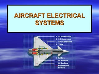
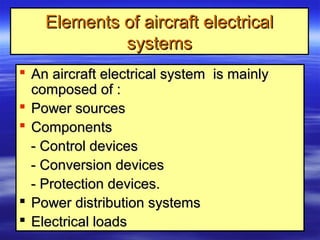
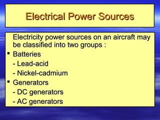
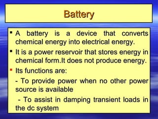


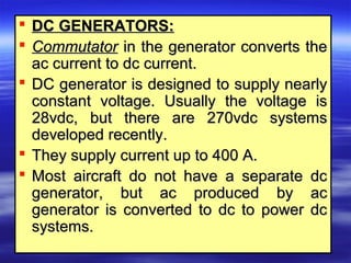
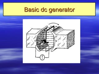

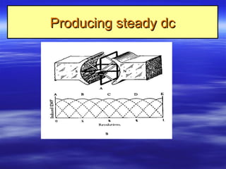
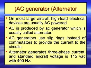
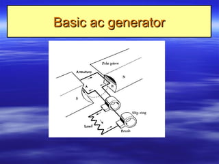
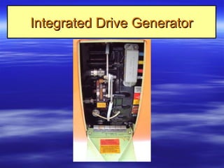
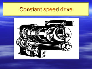
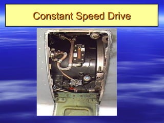
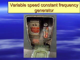


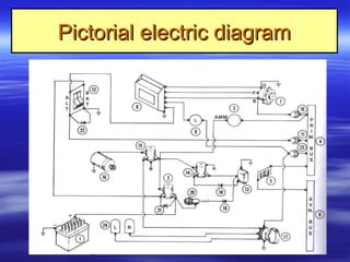
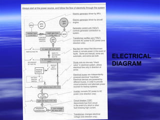
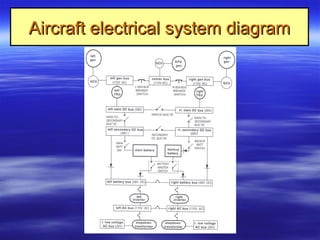

The document discusses aircraft electrical systems. It describes the basic components which include power sources like batteries and generators. Batteries provide power when other sources are unavailable while generators are driven by engines and convert mechanical to electrical energy. Modern systems use constant frequency integrated drive generators or variable speed constant frequency generators to produce steady DC or AC power. The electrical power is controlled and distributed to aircraft components and loads.