
Recommended
More Related Content
What's hot
What's hot (15)
Similar to Pull Out Values Report
Similar to Pull Out Values Report (20)
Recently uploaded
Recently uploaded (20)
Pull Out Values Report
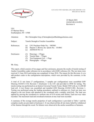
- 1. INFORMATION CONTAINED HEREIN MAY BE SUBJECT TO EXPORT CONTROL LAWS. REFER TO INTERNATIONAL TRAFFIC IN ARMS REGULATION (ITAR) OR THE EXPORT ADMINISTRATION REGULATION (EAR) OF 1979. IT IS THE RESPONSIBILITY OF THE RECIPIENT TO OBTAIN ANY REQUIRED LICENSES TO EXPORT ANY CONTROLLED DATA. 23 March 2021 416365-00-L18-0925, Revision A LN1 67 Mariner Drive Southampton, NY 11968 Attention: Mr. Christopher Gray (Christopher@nillbuildingsolutions.com) Subject: Tensile Strength of Anchor Assemblies References: (a) LN1 Purchase Order No.: 1805001 (b) Dayton T. Brown, Inc. Quote No.: 18-0861 (c) ASTM D1761-12 Enclosures: (1) Drawings – 2 Pages (2) Tensile Data – 7 Pages (3) Test Equipment List – 1 Page (4) Photographs – 4 Pages Mr. Gray, This report, which consists of two pages and four enclosures, presents the results of tensile testing of Anchor Assemblies under reference (a) in accordance with (IAW) reference (b). The test items were received 11 June 2018 and testing was completed 14 June 2018. The reason for this Revision A is to add product codes to the configuration descriptions, which were provided by the customer, in the report. A total of 21 test items (7 configurations, 3 samples per configuration) were assembled IAW Drawing 416365-3-110, Revision 1 (Enclosure 1) by LN1 and provided to DTB for testing. The tensile testing was performed on an Instron Universal Tensile Tester, Model 5569 with an 11,240-lbf load cell. A test fixture was assembled and installed IAW Drawing 416365-2-001, Revision 1. Testing was performed using the loading procedures outlined in reference (c). Each test item was aligned in the test fixture and attached to the crosshead with a suitably sized bolt. The load was applied by moving the crosshead at a uniform rate of 0.10 in/min until failure. Each test was video recorded. The maximum load and crosshead extension at max load were recorded. A summary of the average tensile properties of each configuration is provided in Table 1 and the complete results are provided in Enclosure 2. It was observed that all test items failed by withdrawal of the fastener through the wood. No failures were observed in the anchor assemblies or fasteners.
- 2. 18-0925A Pg 2 Table 1. Summary of tensile test data. Configuration Average Maximum Load (lbf) Average Extension at Max. Load (in) NB4 with King Insert (Aluminum Raised with King Insert) 2,933.49 0.14 NB4 (Aluminum Raised) 3,211.61 0.15 NB1C (Flush Anchor, 3/4 in Bolt) 1,937.84 0.56 NB1 (Flush Anchor, 1/2 Bolted from Underneath) 4,003.76 0.17 NB1AC (Lightning, 5x5) 2,057.00 0.60 NB3 (Small Anchor Flange Flush) 2,083.34 0.15 NB2 (Small Anchor Flange Raised) 2,111.88 0.14 The test items completed all phases of testing. The test results recorded in this report relate only to those items tested. This test report shall not be reproduced, except in full, without written approval of Dayton T. Brown, Inc. If you have any questions, please do not hesitate to contact the undersigned at (631) 589-6300 Ext. 4571. Very truly yours, DAYTON T. BROWN, INC. Donald Landwehrle for Michael Hemphill Project Engineer Warren Halbig Department Manager MH:rb cc: Mr. Lance Nill (lancenillinc@yahoo.com)
- 7. 18-0925A Enc 2 Pg 1 NB4 with King Insert (Aluminum Raised with King Insert) RB 3/18/21
- 8. 18-0925A Enc 2 Pg 2 NB4 (Aluminum Raised) RB 3/18/21
- 9. 18-0925A Enc 2 Pg 3 NB1C (Flush Anchor 3/4 Inch Bolt) RB 3/18/21
- 10. 18-0925A Enc 2 Pg 4 NB1 (Flush Anchor, 1/2 Bolted from Underneath) Flush Anchor Half Inch Bolt RB 3/18/21
- 11. 18-0925A Enc 2 Pg 5 NB1AC (Lightning 5X5) RB 3/18/21
- 12. 18-0925A Enc 2 Pg 6 NB3 (Small Anchor Flange Flush) RB 3/18/21
- 13. 18-0925A Enc 2 Pg 7 NB2 (Small Anchor Flange Raised) RB 3/18/21
- 14. 18-0925A Enclosure 3 Test Equipment List
- 15. 18-0925A Enc 3 Pg 1 Test equipment utilized for the program reported herein was within its assigned interval of calibration. Details are on file at Dayton T. Brown, Inc. and will be made available upon request. 416365-00 Job Sub: CAL DUE DATE ACCURACY MODEL DTB NO. MANUFACTURER ITEM TEST EQUIPMENT LIST TESTER, UNIVERSAL TENSILE W/STATIC LOAD CELLS (2) INSTRON 29-2 5569 07/14/2019 ± 1% of reading
- 17. 18-0925A Enc 4 Pg 1 Photo 1 – Test fixture and setup. Photo 2 – Test fixture and setup.
- 18. 18-0925A Enc 4 Pg 2 Photo 3 – Overview of the NB4 with King Insert (Aluminum Raised with King Insert) configuration. Photo 4 – Overview of the NB4 (Aluminum Raised) configuration.
- 19. 18-0925A Enc 4 Pg 3 Photo 5 – Overview of the NB1C (Flush Anchor, 3/4 in Bolt) configuration. Photo 6 – Overview of the NB1 (Flush Anchor, 1/2 Bolted from Underneath) configuration.
- 20. 18-0925A Enc 4 Pg 4 Photo 7 – Overview of the NB3 (Small Anchor Flange Flush) configuration. Photo 8 – Overview of the NB2 (Small Anchor Flange Raised) configuration.