
Recommended
More Related Content
What's hot
What's hot (20)
Similar to microscopy ppt.pptx
Similar to microscopy ppt.pptx (20)
Recently uploaded
Recently uploaded (20)
microscopy ppt.pptx
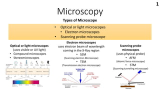
- 1. Microscopy Types of Microscope Optical or light microscopes (uses visible or UV light) • Compound microscopes • Stereomicroscopes • Optical or light microscopes • Electron microscopes • Scanning probe microscope Electron microscopes uses electron beam of wavelength coming in the X-Ray region • SEM (Scanning electron Microscope) • TEM (Transmission electron microscope) Scanning probe microscopes (uses physical probe) • AFM (Atomic force microscope) • STM (Scanning tunneling microscope) 1
- 2. Optical or Light Microscopes • Uses system of lenses and properties of light transmission like Refraction, Diffraction, Reflection, Absorption and Fluorescence. to generate magnified image of a small object. Refraction Diffraction 2 Fluorescence
- 3. Optical or Light Microscopes • The past Centuries has witnessed an enormous growth in the application of optical microscopy for micron and submicron level investigations in a wide variety of disciplines. • But early microscopists (late 18th century) were Facing some difficulties in some of the aspects like image distortion, blurred images, and poor lens design. Problems with the image quality!! • Distortion of microscopic lenses (Spherical and chromatic aberration). • Poor Magnification and resolution. • Poor Contrast of the image. 3
- 4. Optical or Light Microscopes Distortion of microscopic lenses • Distorted images occur when not all the light from parallel rays passing through lens focus at the same focal point. • This distortion based on the shape of lenses is called spherical aberration. • Lights of differing wavelength will also focus at different focal point. This is known as chromatic aberration. Aspherical aberration Corrected Achromatic aberration Corrected 4
- 5. Optical or Light Microscopes In 1830, Joseph Jackson Lister made massive strides in correcting a phenomenon called spherical aberration. Lister built a device by placing weak lenses at precise distances from each other. 5
- 6. Optical or Light Microscopes Magnification • Visible or UV light is Refracted by a series of lenses to achieve magnification. Using two convex lens systems i.e. Eyepiece or Ocular lens and objective lens in combination, the image formed is magnified. Objective lens :- The first lens of a microscope, closest to the object is called the objective. Light passes through the specimen and into the objective which then projects a real, inverted, and magnified image of the specimen to a fixed plane within the microscope that is termed the intermediate image plane. The intermediate image plane is usually located about 10 millimetres below the top of the microscope body tube. • Objectives typically have magnifying powers that range from 4X (or 5X), 10X, 20X, 40X (or 50X), and 100X. 6
- 7. Optical or Light Microscopes Eyepiece (ocular lens) :- The eyepiece or ocular, which fits into the microscope body tube at the upper end, is the farthest optical component from the specimen. Ocular lens further magnifies the primary real image projected by the objective. The eye of the observer sees this secondarily magnified image as if it were at a distance of 10 inches (25 centimetres) from the eye. Their magnification factors vary between 5X and 30X with the most commonly used eyepieces having a value of 10X-15X. 7
- 8. Optical or Light Microscopes Total magnification:- Total visual magnification of the microscope is derived by multiplying the magnification values of the objective and the eyepiece. For instance, using a 5X objective with a 10X eyepiece yields a total visual magnification of 50X and likewise, at the top end of the scale, using a 100X objective with a 30X eyepiece gives a visual magnification of 3000X. Total magnification is also dependent upon the tube length of the microscope. Most standard fixed tube length microscopes have a tube length of 160, 170, 200, or 210 millimetres with 160 millimetres being the most common. Finite Tube Length Microscope (fixed length, objectives can be changed with different microscope) Infinity Corrected Microscope (Length can be changed. Objectives can’t be changed, Additional equipment like vertical illuminators, DIC prism, polarizers can be added) 8
- 9. Optical or Light Microscopes Additional tube lenses will sometimes introduce an additional magnification factor (usually around 1.25-1.5X) that must be taken into account when calculating the visual magnification. This additional magnification factor is referred to as a tube factor. Thus, if a 5X objective is being used with a 15X set of eyepieces, then the total visual magnification becomes 15×5×1.25=93.75X (using a 1.25X tube factor) or 15×5×1.5= 112.5X (using a 1.5X tube factor). 9
- 10. Optical or Light Microscopes Resolving power • Magnifying an image by using microscope is useful only when the details can be preserved accurately and observed. Rayleigh’s criterion:- diffraction of light Limit of resolution:- smallest linear or angular distance between the two objects at which they appear separated(just resolved) Resolving power is the reciprocal of the limit of resolution. 10
- 11. Optical or Light Microscopes Resolving power Smallest distance between the two entities which can be seen as separate entities Is called resolving power. Smaller the value of resolving power, smaller objects can be observed distinctly. Resolving power depends on wavelength of light (λ) and Numerical Aperture (NA) of objective lens. • Using shorter wavelength of light(blue filter, 400nm) and greater value of NA, high resolving power can be achieved. Light microscope has resolving power of 200nm Using oil immersion lens for better resolution • Numerical aperture (NA) is the property of lenses that describes the amount of light that can enter it. It depends on refractive index (n) of the medium filling it. • Air has refractive index of 1 which limits the resolution, but NA can be increased by replacing the air with oil which has refractive index of 1.5 • NA affects the useful magnification that can be achieved. 11
- 12. Optical or Light Microscopes Resolving power • Minimum magnification necessary for the detail present in an image to be resolved, is usually 500 times the numerical aperture (500 × NA). • The maximum useful magnification of an image is usually set at 1000 times the numerical aperture (1000 × NA). Using oil immersion lens With NA of 1.4, magnification of 1400X can be achieved. • Magnifications higher than this value will yield no further useful information or finer resolution of image detail, and will usually lead to image degradation, known as Empty Magnification. Because of Short focal length of oil immersion lens, short working distance is required i.e. Lens and specimen are very close to each other. Shallow depth of field i.e. Thin section of specimen can be focused at a time. 12
- 13. Optical or Light Microscopes Contrast of the image • To achieve better contrast, two methods are available ,i.e. Staining and light illumination. • Light illumination can be either Reflected OR Transmitted Transmitted light illumination (light passes through sample) • Bright Field • Differential interface contrast(DIC) • Dark Field • Phase contrast • Polarization Reflected light Illumination (Light reflected back from the sample) • Fluorescence • Confocal • Multiphoton • TIRF(total internal reflection fluorescence) • Super resolution 13
- 14. Optical or Light Microscopes Contrast of the image • Bright field Used for fixed stained samples. • Differential interference contrast • Unstained, transparent sample appears three dimensional • Dark field Combining light waves that are out of phase Blocking out of the central light rays that ordinarily pass through or around the specimen and allowing only oblique rays to illuminate the specimen. 14
- 15. Optical or Light Microscopes Contrast of the image • Phase contrast Separation of Direct light or undeviated light from diffracted light • Polarization Birefringence :- an incident ray of light is split into two rays, called an ordinary ray and an extraordinary ray, which are polarized 15
- 16. Optical or Light Microscopes Contrast of the image • Fluorescence • Illuminated at one wavelength and observed at different wavelengths. Flurescein Isothiocyanate • Excitation filters • Barrier filters • Confocal Scanning • Beam of light from laser is focused and scanned through 2 mirrors. • Eliminated the diffracted light that blur the image. • Do not form 2D image 16
- 17. Optical or Light Microscopes 1) Compound Microscope • Designed with compound lens system, loaded with several objective lens(5× to 100×) and eyepieces (generally 10x). Upright Microscope Inverted Microscope • Objectives are above the sample stage. • For Fixed samples such as cells and tissues section. • Objectives are below the sample stage. • For live cell imaging. • Sterile working conditions. 17
- 18. Optical or Light Microscopes 2) Stereomicroscopes • Comparatively low power as compared to compound microscopes.(usually below 100×) objective is [1× to 2×] and eyepiece is 10× • They can have Fixed magnification system or Zoom magnification system. • Working distance is much longer. • Also known as dissecting microscope 18
- 19. • Uses High voltage (60,000 volt) beam of electron of 0.005 nm wavelength, Permitting resolution of 0.2 nm which is 1000 times greater than optical microscopes. Sample preparation for x-ray microanalysis:- Dehydration and Fixation, Staining, Thin sectioning (ultra microtome), Freeze etching (Great potential for creating artefacts). Electron Microscopes Staining freeze etching ultra microtome 19
- 20. Electron Microscopes 1) TEM:- Transmission Electron Microscope Electromagnetic lens • Used to view thin specimens through which electrons can pass generating a projection image. • Hot Tungsten Filament in the electron gun provides electron beam. • Vacuum system is maintained to prevent collision with electron. 20
- 21. Electron Microscopes 2) SEM:- Scanning Electron Microscope • Primary electron beam knocks electron out of specimen. This secondary electron are transmitted to detector. • More intense signal is developed. • Gives detailed topography of specimen surface. 21
- 22. Scanning probe microscope • Images formation using a physical probe that scans the specimen surface. • Resolution varies somewhat from technique to technique(atomic resolution) • This family of techniques can be called “piezoelectric techniques”. • The data are typically obtained as a two-dimensional grid of data points, visualized in false colour as a computer image. • The nature of an SPM probe tip depends entirely on the type of SPM being used. • The apex of the probe defines the resolution of the microscope, the sharper the probe the better the resolution “contact mode” or “tapping mode.” Contact mode maintains a constant force between the cantilever tip of the microscope and the sample surface(fast production of the image). Tapping mode involves oscillation of the cantilever, so the tip intermittently comes into contact with the sample surface(useful for softer samples). 22
- 23. Scanning probe microscope 1) AFM:-Atomic Force Microscope • measuring intermolecular forces and sees atoms by using probed surfaces of the specimen in nanoscale. • Takes the image of the surface topography of the sample by scanning the cantilever over a section of interest. 23
- 24. Scanning probe microscope 2) STM:- Scanning Tunneling Microscope 24 • Used to obtain ultra-high resolution images at the atomic scale, without using light or electron beams. • Quantum mechanical process (electron tunneling),i.e. Electrons travel a barrier (in this case, a tiny gap between the tip and surface) • No physical contact • This tunneling current is highly sensitive and can be detected. • Image can be seen in Armstrong. • Used in material science, measures electron density gradient.