Downloaded 206 times
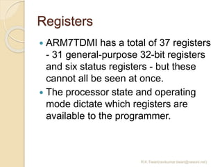
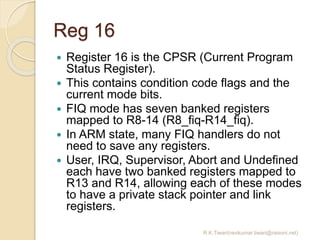
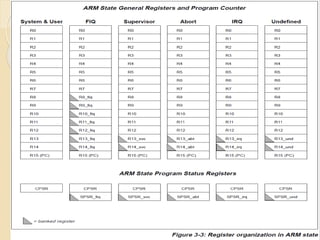
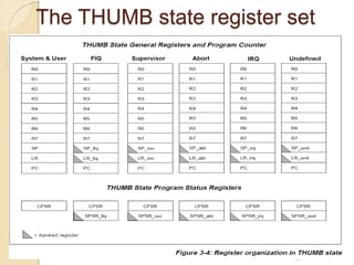
![Reg 15
Register 15 holds the Program
Counter (PC).
In ARM state, bits [1:0] of R15 are
zero and bits [31:2] contain the PC. In
THUMB state, bit [0] is zero and bits
[31:1] contain the PC.
R.K.Tiwari(ravikumar.tiwari@raisoni.net)](https://image.slidesharecdn.com/es-arm2-150619061521-lva1-app6892/85/ARM-Programmer-s-Model-14-320.jpg)
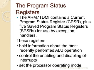
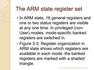
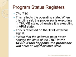
![Program Status Registers
The control bits
The bottom 8 bits of a PSR
(incorporating I, F, T and M[4:0]) are
known collectively as the control bits.
These will change when an exception
arises.
If the processor is operating in a
privileged mode, they can also be
manipulated by software.
R.K.Tiwari(ravikumar.tiwari@raisoni.net)](https://image.slidesharecdn.com/es-arm2-150619061521-lva1-app6892/85/ARM-Programmer-s-Model-23-320.jpg)
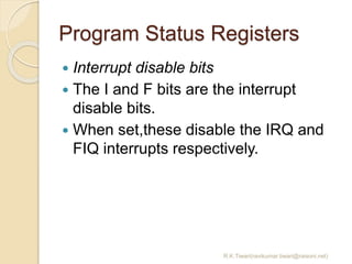
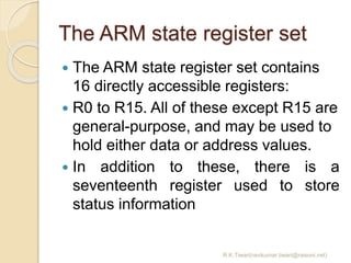
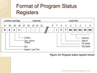
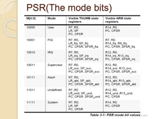
![PSR(The mode bits)
The M4, M3, M2, M1 and M0 bits (M[4:0]) are
the mode bits.
These determine the processor’s operating
mode, as shown in òTable 3-1: PSR mode bit
values on page 3-9.
Not all combinations of the mode bits define a
valid processor mode. Only those explicitly
described shall be used.
The user should be aware that if any illegal
value is programmed into the mode bits,
M[4:0], then the processor will enter an
unrecoverable state.
If this occurs, reset should be applied.
R.K.Tiwari(ravikumar.tiwari@raisoni.net)](https://image.slidesharecdn.com/es-arm2-150619061521-lva1-app6892/85/ARM-Programmer-s-Model-26-320.jpg)
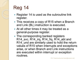
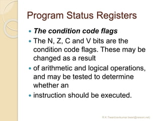
![Reset
When nRESET goes HIGH again,
ARM7TDMI:
1 Overwrites R14_svc and SPSR_svc by
copying the current values of the PC
and CPSR into them. The value of the
saved PC and SPSR is not defined.
2 Forces M[4:0] to 10011 (Supervisor
mode), sets the I and F bits in the CPSR,
and clears the CPSR’s T bit.
3 Forces the PC to fetch the next
instruction from address 0x00.
4 Execution resumes in ARM state.
R.K.Tiwari(ravikumar.tiwari@raisoni.net)](https://image.slidesharecdn.com/es-arm2-150619061521-lva1-app6892/85/ARM-Programmer-s-Model-37-320.jpg)

The document discusses the programmer's model of the ARM7TDMI processor. It describes the two operating states (ARM and THUMB) and how transitions occur between them using the BX instruction or exceptions. It also covers memory formats, data types, operating modes, registers, program status registers, exceptions, and the actions taken when entering or leaving exceptions.