Engineering Materials
•Download as PPTX, PDF•
8 likes•1,138 views

Engineering Material, Material Classification, characteristics of materials like metal, ceramics, organic, composites and semiconductors, Engineering requirements of materials, Properties of Engineering materials, factors affecting mechanical properties, Factors affecting the selection of materials for engineering purposes, Destructive and non-destructive testing, Tensile test, stress-strain diagram, spark test, macro etching, chemical analysis, Izod Impact testing, Charpy Impact testing, Fracture, Ductile Fracture, Brittle fracture, Ductile to brittle transition, creep failure, fatigue failure, radiography testing, dye penetration testing, magnetic particle testing, ultrasonic testing,

Recommended
More Related Content
What's hot
What's hot (20)
Similar to Engineering Materials
Similar to Engineering Materials (20)
More from Ratnadeepsinh Jadeja
More from Ratnadeepsinh Jadeja (20)
Recently uploaded
Recently uploaded (20)
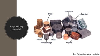
Engineering Materials
- 2. Material • A material is that out of which anything is or may be made. A material relates itself to matter. • Material comprise a wide range of metals and non metals which must be operated upon to form the finished product.
- 3. Material Classification • Most engineering materials may be classified into one of the following types (a) Metals – Ferrous and Non-ferrous (b) Ceramics (c) Organics (d) Composites (e) Semiconductors
- 4. Metals • Metals are composed of elements which are readily give up electrons to provide a metallic bond and electrical conductivity. • Metals generally possess the following characteristics: 1. Luster 2. Hardness 3. Low specific heat 4. Plastic deformability 5. Good thermal and electrical conductivity 6. Relatively high melting point 7. Strength 8. Ductility 9. Malleability 10. Opaqueity 11. Stiffness 12. Rigidity 13. Formability 14. Machinability 15. Weldability 16. Castability 17. Dimensional stability Examples of commonly employed metals are: Iron, Aluminum, Copper, Zinc, Magnesium, etc…
- 5. Ceramic Materials • Ceramics usually consists of oxides, nitrides, carbides, silicates or borides of various metals. • Ceramics are any inorganic, non metallic solids (or super cooled liquids) processed or used at high temperatures. • Such materials contain both iconic and covalent bonds. • Ceramics generally possess the following characteristics: 1. Brittleness 2. Rock like appearance 3. Resistance to high temperature 4. Hardness 5. Abrasiveness 6. Insulation (to flow of electric current 7. Corrosion resistance 8. Opaque to light 9. High temperature strength. Examples of commonly employed ceramic are: 1. Sand 2. Glass 3. Brick 4. Concrete 5. Silicon carbide 6. Boron nitride 7. Abrasives 8. Cement 9. Insulators 10. Tungusten carbide 11. Refractories 12. Plaster.
- 6. Organic Materials • They are polymeric materials composed of carbon compounds. Polymers are solid composed of long molecular chains • Organic materials generally possess the following characteristics: 1. light weight 2. Combustible 3. Soft 4. Ductile 5. Dimensionally unstable 6. Poor conductors 7. Poor resistance to temperature. Etc… Examples of commonly employed organic materials are: 1. Rubber 2. Plastic 3. Paper 4. Fuels 5. Wood 6. Lubricants 7. Textiles 8. Paints and finishes 9. Adhesives 10. Explosives Organic materials find following uses: 1. As electric insulation 2. As fuels 3. As vitamins and medicines 4. For improving appearance 5. For protection against high temp 6. As explosives 7. For protection against corrosion 8. As refrigerants 9. As adhesives 10. As detergent 11. As lubricants
- 7. Composites • Composites materials consists of more than one material type. Fiber glass is a familiar example, in which glass fiber are embedded within a polymeric material. A composite is design to display a combination of the best characteristics of each of the component materials. Fiberglass acquire strength of the glass and flexibility from the polymer. Semiconductors • Semiconductors have electrical properties that are intermediate between the electrical conductors and insulators. • The semiconductors have made possible the advent of integrated circuitry that has totally revolutionized the electronics and computer industries.
- 8. Engineering Requirements of materials The main engineering requirements of materials fall under three categories, 1. Fabrication Requirements 2. Service requirements 3. Economic requirements.
- 9. Properties of Engineering Materials Property of a material is a factor that influences qualitatively or quantitatively the response of a given material to imposed stimuli and constraints, e.g., forces, temperature, etc. Different material properties are: 1. Mechanical properties 2. Thermal properties 3. Electrical properties 4. Magnetic properties 5. Chemical properties 6. Optical properties 7. Physical properties 8. Technological properties
- 10. Mechanical Properties • Mechanical properties include those characteristics of material that describe its behavior under the action of external forces. • Mechanical properties can be determine by conducting experimental tests on the material specimen. • Various mechanical properties are : 1. Elasticity 2. Plasticity 3. Toughness 4. Resilience 5. Tensile strength 6. Yield strength 7. Impact strength 8. Ductility 9. Malleability 10.Brittle ness 11.Hardness 12.Fatigue 13.Creep 14.Wear Resistance
- 11. Factors affecting mechanical properties Mechanical properties of materials are affected due to : 1. Alloy contents such as addition of W, Cr, etc., improve hardness and strength. 2. Fine grain size materials exhibit higher strengths and vice versa. 3. Crystal imperfection such as dislocations reduce the strength. 4. Excessive cold working produces strain-hardening and the material may crack. 5. Manufacturing defects such as cracks, blowholes, etc., reduces the strength.
- 12. Effects of Grain size on Properties of Metals On the basis of grain size, materials may be classifies as: 1. Course grained materials, (the grain size is large). 2. Fine grained materials, (the grain size is small). • Fine grained material possess higher strength, toughness, hardness and resistance to suddenly applied force, better fatigue resistance and impact strength, crack resistance and provide better finish in deep drawing. This materials preferred for structural applications with greater yield stresses than course grained materials. • A course grained material is responsible for surface roughness. It possesses more ductility, malleability and better machinability, are difficult to polish or plating. • Course grained steels have grater depth of hardening power as compared to fine grained ones. • At elevated temperatures, course grained materials show better creep strength than fine grained ones.
- 13. Effects of Heat treatment on properties of metals • Heat treatment is an operation or combination of operations involving heating and cooling of a metal/alloy in solid state to obtain desirable properties and conditions. • Some important heat treatment processes are: • Annealing • Normalising • Hardening • Tempering • Martempering • Austempering etc…
- 14. Effects of Heat treatment on properties of metals • One or the other heat treatment processes produces the following effects on the properties of metals: 1. Hardens and strengthens the metals. 2. Improves machinability. 3. Change or refines grain size. 4. Soften metals for further working as in wire drawing. 5. Improves ductility and toughness. 6. Increase resistance of materials to heat, wear, shock and corrosion. 7. Improves electrical and magnetic properties. 8. Homogenises the metal structure. 9. Relieves internal stresses developed in metals/alloy during cold working, welding, casting, forging etc.. 10. Produces a hard wear resistant surface on a ductile steel piece (as in case of hardening) 11. Improves thermal properties such as conductivity.
- 15. Thermal Properties • By thermal property meant the response of a material to the application of heat. • Thermal properties such as: 1. Heat capacity 2. Specific heat 3. Thermal expansion 4. Melting point 5. Thermal conductivity 6. Thermal shock resistance 7. Thermal stability
- 16. Electrical Properties • Different electrical properties are: 1. Resistivity 2. Conductivity 3. Temperature coefficient of resistance 4. Dielectric strength 5. Thermoelectricity. 6. Electrochemical phenomena 7. Electrophysical effects 8. Electromechanical effects.
- 17. Magnetic Properties • Some of the magnetic properties are: 1. Permeability 2. Coercive force 3. Hysteresis 4. Superconductivity.
- 18. Chemical Properties • Some of the chemical properties are: 1. Corrosion Resistance 2. Chemical Resistance 3. Acidity or Alkalinity.
- 19. Optical Properties • Some of the optical properties are: 1. Refractive index 2. Absorptivity and Absorption coefficient 3. Reflectivity.
- 20. Physical Properties • Some of the physical properties are: 1. Dimensions 2. Appearance 3. Colour 4. Density 5. Melting point 6. Porosity 7. Structure etc.
- 21. Technological Properties • Some of the technological properties are: 1. Castability 2. Machinability 3. Weldability 4. Solderability 5. Workability/Formability.
- 22. Factors affecting the selection of materials for engineering purposes 1. Properties of Materials 2. Performance Requirements 3. Material’s Reliability 4. Safety 5. Physical Attributes 6. Environmental conditions 7. Availability 8. Disposability and Recyclability 9. Economic Factor
- 24. What is Destructive Testing? • Destructive testing is undertaken in order to understand a specimen’s performance or material behavior, these procedures are carried out to the test specimen’s failure. Destructive testing procedures can either follow specific standards or can be tailored to reproduce set service conditions. • Destructive testing methods are commonly used for materials characterization, fabrication validation, failure investigation, and can form a key part of engineering critical assessments
- 25. Tensile Test• In tension test ends of a test piece are fixed into grips connected to a straining device and to a load measuring device. The test involves straining a test piece by tensile force generally to fracture for the purpose of determining one or more of the mechanical properties. • The straining unit of universal testing machine consists of main hydraulic cylinder with robust base inside and piston which moves up and down. The lower table connected to main piston through a ball & the ball seat is joined to ensure axial loading. There is a connection between lower table and upper head assembly that moves up and down with main piston. The control panel consists of a power pack complete with drive motor and an oil tank, control valves and an autographic recorder. Load Indicator system consists of a large dial and a pointer. A dummy pointer is provided to record the maximum load reached during the test.
- 26. Tensile Test • Load is applied by a hydrostatically lubricated ram. Main cylinder pressure is transmitted to the cylinder of the pendulum dynamometer system housed in the control panel. The cylinder of the dynamometer is also of self-lubricating design. The load transmitted to the cylinder of the dynamometer is transferred through a lever system to a pendulum. Displacement of the pendulum actuates the rack and pinion mechanism which operates the load indicator pointer and the autographic recorder. The deflection of the pendulum represents the absolute load applied on the test specimen. Return movement of the pendulum is effectively damped to absorb energy in the event of sudden breakage of a specimen.
- 28. Spark Test • Spark testing is a method of determining the general classification of ferrous materials. It normally entails taking a piece of metal, usually scrap, and applying it to a grinding wheel in order to observe the sparks emitted. • These sparks can be compared to a chart or to sparks from a known test sample to determine the classification. Spark testing also can be used to sort ferrous materials, establishing the difference from one another by noting whether the spark is the same or different. • Spark testing is used because it is quick, easy, and inexpensive. Moreover, test samples do not have to be prepared in any way, so, often, a piece of scrap is used. The main disadvantage to spark testing is its inability to identify a material positively; if positive identification is required, chemical analysis must be used. The spark comparison method also damages the material being tested, at least slightly. • Spark testing most often is used in tool rooms, machine shops, heat treating shops, and foundries.
- 29. Macro-etching • Macro-etching, also known as deep etching, involves etching specimens prepared with a suitable acid or reagent for macrostructural examination at low magnifications and rating by a grades series of photographs showing the incidence of certain conditions such as: cracks, pipe, center voids, center unsoundness, pinholes, porosity, white band, chill structure, dendritic structure, inclusions, hydrogen flakes, segregation, banding, grain size, mold slag, and other discontinuities or defects such as laps and seams.
- 30. Chemical Analysis • Chemicals analysis determines the composition of the material. The chemical composition of a metal alloy is the starting point for a right classification of the material itself. Quantitative chemical analysis is performed to accurately determine the concentration of elements in the material
- 31. Izod Impact Testing • The Izod impact test was named for English engineer Edwin Gilbert Izod, who first described the test method in 1903. The test apparatus and specimen design are very similar to Charpy impact, with some notable differences, including the orientation of the specimen, which is clamped into the apparatus vertically with the notch facing toward the pendulum. The pendulum then impacts the sample at a specified area above the notch. • One of the main differences from Charpy impact is that Izod impact testing can be performed on either plastic or metallic specimens. Plastic samples are typically a 64 x 12.7 x 3.2 mm bar with a machined V-shaped notch. Metallic samples are typically round 127 x 11.43 mm bar with 1 or 3 machined V-shaped notch(es). • Common Izod impact test methods include ASTM D256, ASTM E23, and ISO 180.
- 32. Charpy Impact Testing • The Charpy impact test was developed by S.B. Russell and Georges Charpy at the turn of the 20th century. It remains to this day one of the most popular impact testing methods due to the relative ease of creating samples and obtaining results. The test apparatus consists of a weighted pendulum, which is dropped from a specified height to contact the specimen. The energy transferred to the material can be inferred by comparing the difference in the height of the pendulum before and after the fracture. • A Charpy test specimen, which is placed horizontally into the machine, is typically a 55 x 10 x 10mm (2.165" x 0.394" x 0.394") bar with a notch machined into one of the faces. This notch, which can be either V-shaped or U-shaped, is placed facing away from the pendulum and helps to concentrate the stress and encourage fracture. Testing can be performed at both ambient and reduced temperatures, sometimes as low as -425F. • Charpy impact testing is most performed to ASTM E23, ASTM A370, ISO 148, or EN 10045-1. While the test is most performed on metals, there are also a few standards that exist for plastics and polymers, including ASTM D6110 and ISO 179.
- 33. Fracture • Fracture is the separation of an object or material into two or more pieces under the action of stress. The fracture of a solid usually occurs due to the development of certain displacement discontinuity surfaces within the solid. • If a displacement develops perpendicular to the surface of displacement, it is called a normal tensile crack or simply a crack. • If a displacement develops tangentially to the surface of displacement, it is called a shear crack, slip band, or dislocation. • Brittle fractures occur with no apparent deformation before fracture; ductile fractures occur when visible deformation does occur before separation. Fracture strength or breaking strength is the stress when a specimen fails or fractures. A detailed understanding of how fracture occurs in materials may be assisted by the study of fracture mechanics.
- 34. Ductile Fracture • Ductile fracture is a type of fracture characterized by extensive deformation of plastic or "necking." This usually occurs prior to the actual fracture. The term "ductile rupture" refers to the failure of highly ductile materials. In such cases, materials pull apart instead of cracking. • In ductile fracture, there is absorption of massive amounts of energy and slow propagation before the fracture occurs.
- 35. Brittle Fracture • Brittle Fracture is the sudden, very rapid cracking of equipment under stress where the material exhibited little or no evidence of ductility or plastic degradation before the fracture occurs. Unlike most other tensile failures, where the material plastically strains under overload conditions and becomes thinner until the point of rupture, when a piece of equipment suffers a brittle fracture, there is no thinning or necking down. Rather, this damage mechanism often causes cracking without warning, sometimes fracturing equipment into many pieces. Ductile Fracture Brittle Fracture
- 36. Ductile to Brittle transition • At low temperatures, some metals that would be ductile at room temperature become brittle. This is known as a ductile to brittle transition.
- 37. Creep Failure • In materials science, creep is the tendency of a solid material to move slowly or deform permanently under the influence of persistent mechanical stresses. It can occur as a result of long-term exposure to high levels of stress that are still below the yield strength of the material. Creep is more severe in materials that are subjected to heat for long periods and generally increases as they near their melting point.
- 38. Fatigue Failure • Fatigue failure is defined as the tendency of a material to fracture by means of progressive brittle cracking under repeated alternating or cyclic stresses of an intensity considerably below the normal strength.
- 40. What is Non-Destructive Testing? • Non-destructive testing (NDT) is a wide group of analysis techniques used in science and technology industry to evaluate the properties of a material, component or system without causing damage. • Non-destructive examination (NDE), non-destructive inspection (NDI), and non- destructive evaluation (NDE) are also commonly used to describe this technology because NDT does not permanently alter the specimen being inspected, it is a highly valuable technique that can save both money and time in product evaluation, troubleshooting, and research.
- 41. Radiography Testing • Radiographic Testing is a non-destructive testing method which uses either x-rays or gamma rays to examine the internal structure of manufactured components identifying any flaws or defects. • In Radiography Testing the test-part is placed between the radiation source and receiver. The material density and thickness differences of the test-part will reduce the penetrating radiation through interaction processes involving scattering and/or absorption. The differences in absorption are then recorded. • There are two different radioactive sources available for industrial use; X-ray and Gamma-ray. These radiation sources use higher energy level, i.e. shorter wavelength, versions of the electromagnetic waves. Because of the radioactivity involved in radiography testing, it is of paramount importance to ensure that the Local Rules is strictly adhered during operation.
- 42. Dye Penetration Testing • Dye penetrant inspection (DP), also called liquid penetrate inspection (LPI) or penetrant testing (PT), is a widely applied and low-cost inspection method used to check surface defects in all non-porous materials (metals, plastics, or ceramics). The penetrant may be applied to all non-ferrous materials and ferrous materials. LPI is used to detect casting, forging and welding surface defects such as hairline cracks, surface porosity, leaks in new products, and fatigue cracks on in-service components. • Inspection steps • Pre cleaning • Application of Penetrant • Excess Penetrant Removal • Application of Developer • Inspection • Post Cleaning
- 43. Magnetic Particle Testing • Magnetic particle Inspection (MPI) is a process for detecting surface and shallow subsurface discontinuities in ferromagnetic materials such as iron, nickel, cobalt, and some of their alloys. • The process puts a magnetic field into the part. The piece can be magnetized by direct or indirect magnetization. Direct magnetization occurs when the electric current is passed through the test object and a magnetic field is formed in the material. • Indirect magnetization occurs when no electric current is passed through the test object, but a magnetic field is applied from an outside source. The magnetic lines of force are perpendicular to the direction of the electric current, which may be either alternating current or some form of direct current.
- 44. Ultrasonic Testing • Ultrasonic testing is a non-destructive testing techniques based on the propagation of ultrasonic waves in the object or material tested. In most common UT applications, very short ultrasonic pulse-waves with center frequencies ranging from 0.1-15 MHz, and occasionally up to 50 MHz, are transmitted into materials to detect internal flaws or to characterize materials. • Ultrasonic testing is often performed on steel and other metals and alloys, though it can also be used on concrete, wood and composites, albeit with less resolution. It is used in many industries including steel and aluminum construction, metallurgy, manufacturing, aerospace, automotive and other transportation sectors.